EP4521056A2 - Mécanismes de verrouillage de sécurité pour armes portatives, notamment arbalètes et armes à feu, tels que des fusils, des carabines et analogues - Google Patents
Mécanismes de verrouillage de sécurité pour armes portatives, notamment arbalètes et armes à feu, tels que des fusils, des carabines et analogues Download PDFInfo
- Publication number
- EP4521056A2 EP4521056A2 EP25154091.0A EP25154091A EP4521056A2 EP 4521056 A2 EP4521056 A2 EP 4521056A2 EP 25154091 A EP25154091 A EP 25154091A EP 4521056 A2 EP4521056 A2 EP 4521056A2
- Authority
- EP
- European Patent Office
- Prior art keywords
- lock
- lock tongue
- lock mechanism
- trigger
- slot
- Prior art date
- Legal status (The legal status is an assumption and is not a legal conclusion. Google has not performed a legal analysis and makes no representation as to the accuracy of the status listed.)
- Pending
Links
Images






























Classifications
-
- F—MECHANICAL ENGINEERING; LIGHTING; HEATING; WEAPONS; BLASTING
- F41—WEAPONS
- F41A—FUNCTIONAL FEATURES OR DETAILS COMMON TO BOTH SMALLARMS AND ORDNANCE, e.g. CANNONS; MOUNTINGS FOR SMALLARMS OR ORDNANCE
- F41A17/00—Safety arrangements, e.g. safeties
- F41A17/06—Electric or electromechanical safeties
-
- F—MECHANICAL ENGINEERING; LIGHTING; HEATING; WEAPONS; BLASTING
- F41—WEAPONS
- F41A—FUNCTIONAL FEATURES OR DETAILS COMMON TO BOTH SMALLARMS AND ORDNANCE, e.g. CANNONS; MOUNTINGS FOR SMALLARMS OR ORDNANCE
- F41A17/00—Safety arrangements, e.g. safeties
- F41A17/46—Trigger safeties, i.e. means for preventing trigger movement
-
- F—MECHANICAL ENGINEERING; LIGHTING; HEATING; WEAPONS; BLASTING
- F41—WEAPONS
- F41A—FUNCTIONAL FEATURES OR DETAILS COMMON TO BOTH SMALLARMS AND ORDNANCE, e.g. CANNONS; MOUNTINGS FOR SMALLARMS OR ORDNANCE
- F41A17/00—Safety arrangements, e.g. safeties
- F41A17/46—Trigger safeties, i.e. means for preventing trigger movement
- F41A17/54—Protecting-caps for trigger guards; Trigger locking pieces mounted on, or within, the trigger guard
-
- F—MECHANICAL ENGINEERING; LIGHTING; HEATING; WEAPONS; BLASTING
- F41—WEAPONS
- F41A—FUNCTIONAL FEATURES OR DETAILS COMMON TO BOTH SMALLARMS AND ORDNANCE, e.g. CANNONS; MOUNTINGS FOR SMALLARMS OR ORDNANCE
- F41A17/00—Safety arrangements, e.g. safeties
- F41A17/64—Firing-pin safeties, i.e. means for preventing movement of slidably- mounted strikers
-
- F—MECHANICAL ENGINEERING; LIGHTING; HEATING; WEAPONS; BLASTING
- F41—WEAPONS
- F41A—FUNCTIONAL FEATURES OR DETAILS COMMON TO BOTH SMALLARMS AND ORDNANCE, e.g. CANNONS; MOUNTINGS FOR SMALLARMS OR ORDNANCE
- F41A17/00—Safety arrangements, e.g. safeties
- F41A17/74—Hammer safeties, i.e. means for preventing the hammer from hitting the cartridge or the firing pin
Definitions
- US Patent No. 6,550,175 to Parker discloses a user friendly gunlock, which is attached to a trigger guard of a firearm, which releases the lock to block the trigger based on a number combination (or similar) is entered properly to the gunlock.
- Recce discloses unauthorized user prevention device and method, which prevents an unauthorized / unrecognizable operator from using a firearm based on a pressure signature profile / grip profile(s) of an authorized operator(s) for the firearm which are stored. Recce requires, however, a special latching and internal trigger lock mechanism, such that a mechanical force / movement would not be propagated from the trigger to the hammer of the firearm to block the firing sequence thereof.
- the biometrically-enabled gun has a biometric sensor for reading the biometric information of an operator (such as finger print) to determine wither the operator is authorized to operate the firearm.
- Kloepfer / Kloepfer 2 lock the firing sequence by obstructing movement of a trigger bar.
- the present invention directs to safety lock mechanisms for portable weapons, including, but not limited to, crossbows and firearms, such as guns, rifles and alike, that provide enabling means to automatically or semi-automatically lock, or lock and unlock a firing sequence thereof.
- a safety lock mechanism for a portable weapon comprising an actuator, and locking means operable from an unlocked state to a locked state by the actuator for blocking a firing sequence of the portable weapon.
- the actuator may include an electromagnet, and a permanent magnet, wherein the permanent magnet is affixed to the locking means, and the electromagnet actuates the locking means through the permanent magnet.
- the locking means may include a bar member for blocking the firing sequence at a trigger, a trigger lever, a hammer, or a firing pin of the portable weapon.
- the locking means is operable from the locked state to the unlocked state.
- the actuator comprises a motor; and a gear, wherein the gear cooperates with the locking means, and the motor actuates the locking means through the gear.
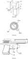
- an automatic spring-type lock mechanism for a portable weapon such as a handgun or alike, comprising a lock cover, a lock shell, and a lock tongue actuator, which would be installed at the front end of the firing pin of the portable weapon.
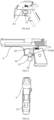
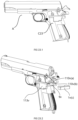
- an automatic spring-type lock mechanism for a handgun or alike which is disposed on the slide near the hammer of the handgun.
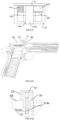
- an automatic spring-type lock mechanism for a handgun or alike which is disposed at the grip of a handgun, which blocks the trigger at the rear side of the trigger of the handgun.
- an automatic spring-type lock mechanism for a handgun or alike which is disposed at the trigger guard to block or release at the rear of the trigger of the handgun.
- an automatic spring-type lock mechanism for a handgun or alike which is disposed at the position which is about or is adjacent to the front end of the firing pin on the slide of the handgun to block or release the filing pin from rushing to a bullet.
- an automatic spring-type lock mechanism for a handgun or alike which is mounted on the position corresponding to firing pin circular slot of the gun slide on the handgun to block or release the firing pin from moving.
- an automatic spring-type lock mechanism for a handgun or alike which is disposed at the end of the slide, which is adjacent with the hammer to block or release the hammer from hitting the firing pin.
- a gear-type trigger lock mechanism for a handgun or alike for blocking or releasing a pulling action for the trigger of the handgun.
- a gear-type trigger lock mechanism for a handgun or alike which includes a lock shell, a lock cover and a lock tongue actuator, including a motor, a driving gear, an idler gear and/or gear set, and a bar member, where the bar member blocks or releases the trigger of the handgun.
- a gear-type trigger lock mechanism for a handgun or alike which includes a lock shell, a lock cover and a lock tongue actuator, including a motor, a driving gear(s), and a bar member, where the bar member blocks / releases the trigger of the handgun.
- a gear-type trigger lock mechanism which includes a lock shell, a lock cover and a lock tongue actuator, including a motor, a driving gear(s), and a bar member, where the bar member blocks or releases the firing pin of the handgun.
- a gear-type trigger lock mechanism for a handgun or alike includes a lock shell, a lock cover and a lock tongue actuator, including a motor, a driving gear(s), an idler gear and/or gear set, and a bar member, where the bar member blocks or releases the hammer from hitting the firing pin of the handgun.
- a semi-automatic electromagnetic telescoping lock mechanism for a handgun or alike which includes a lock shell, a lock cover and a lock tongue actuator, including a lock tongue spring, an electromagnet, a lock tongue limit spring, lock tongue limit block and a bar member, where the bar member blocks the trigger of the handgun.
- a semi-automatic lock mechanism for a handgun or alike which includes a lock shell, lock cover and a lock tongue actuator, including a lock tongue spring, an electromagnet, a lock tongue limit spring, a lock tongue limit block and an arc member, where the arc member blocks the trigger of the handgun.
- a semi-automatic lock mechanism which includes a lock shell, lock cover and a lock tongue actuator, including a lock tongue spring, an electromagnet, a lock tongue limit spring, lock tongue limit block and a bar member, where the bar member blocks the trigger of the handgun.
- a semi-automatic lock mechanism which includes a lock shell, a lock cover and a lock tongue actuator, including a lock tongue spring, an electromagnet, a lock tongue limit spring, a lock tongue limit block and an arc member, where the arc member blocks the trigger of the handgun.
- a semi-automatic lock mechanism for a handgun or alike which includes a lock shell, a lock cover and a lock tongue actuator, including a lock tongue spring, an electromagnet, a lock tongue limit spring, lock tongue limit block and a bar member, where the arc member blocks the trigger of the handgun.
- a semi-automatic lock mechanism for a handgun or alike comprises a lock shell, a lock cover and a lock tongue actuator, including a lock tongue spring, a push-pull solenoid and an arc member, where the arc member blocks the trigger of the handgun.
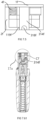
- a pull-rod style trigger lock mechanism for a handgun or alike, includes a lock shell, a bar member, a pull-rod, and a self-holding solenoid, where the bar member operably extends / retract to block / release the movement of the trigger of the handgun.
- a trigger lever lock mechanism for a handgun or alike, which blocks or release the trigger lever of the handgun.
- a tapeline-type trigger lock mechanism that may be installed on a trigger guard of a handgun or alike.
- the lock mechanism has a lock tongue which is attached to a trigger of the handgun and a tapeline which is wind around a tapeline disk, where the movement of the trigger is controlled by controlling the movement of the tapeline disk.
- a box-style lock mechanism that may be installed around or about a trigger guard of a handgun or alike.
- the lock mechanism has a finger window / hole for providing/restricting an access to the trigger.
- An actuator slidably operates the finger window to allow or restrict the access to the trigger.
- a lock mechanism that may be installed on a handgun or alike that replaced a rotary shaft and actuating lever of the original safety mechanism of the handgun.
- the controller M1 when the controller M1 enters in an operational state, would ensure that the firing sequence of the portable weapon is locked initially.
- the controller M1 would permit unlocking the firing sequence of the portable weapon only when the controller M1 conforms/detects the safe environmental condition(s) to use it or receives a remote control information / command(s), etc.
- the controller M1 controls the driver M2 to drive an actuator M3 for actuating the safety lock mechanism to lock the firing sequence of the portable weapon.
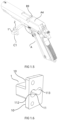
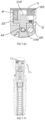
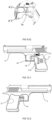
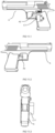
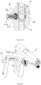
- the lock tongue actuator rod 314 When the handgun A is locked, the lock tongue actuator rod 314 is in the initial state, where the lock tongue actuator rod 314 extends out through the lock tongue extending hole 28.
- the lock tongue actuator rod 314 blocks the space between the firing pin A6 and a bullet (as shown in FIG 1.71, FIG 1.72 , the firing pin A6 is behind the lock tongue actuator rod 314, thus not shown therein). Even if the firing pin A6 has the energy to rush towards the bullet, the strike action will only reach the lock tongue actuator rod 314, but will not reach to the bullet, so the bullet cannot be fired.
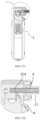
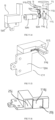
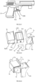
- the lock mechanism C2 includes the lock cover 2a, the lock shell 1a, and the lock tongue actuator 3a.
- the magnet slot 282a and a lock tongue extending hole 28a are located on the lock cover 2a, and the magnet slot 282a corresponds to the permanent magnet 30a.
- the lock tongue slot 112a and the electromagnet installing slot 113a on the lock shell 1a correspond to the lock tongue extending hole 28a and the magnet slot 282a on the lock cover 2a.
- the lock tongue actuator rod 314a has, preferably, a cylindrical structure, however, the structure of the lock tongue actuator rod 314a may be in other shapes, as long as it facilitates blocking the hammer A5 from striking the firing pin A6 as described below.
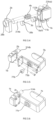
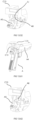
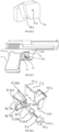
- the automatic spring-type lock mechanism C3 comprises a lock shell 1b, which is box-shaped.
- the lock shell 1b includes a lock core cavity 11b and a lock cover frustum 21 b(a).
- the lock core cavity 11b includes a lock tongue slot 112b and an electromagnet installing slot 113b.
- the lock cover 2b has a lock tongue extending hole 28b, a lock cover slot 21b.
- a lock tongue extending hole 28b corresponds to the lock tongue slot 112b on the lock cover 2b
- a lock cover slot 21b corresponds to the lock cover frustum 21b(a).
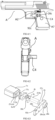
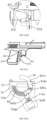
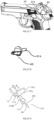
- the lock mechanism C4 includes a lock cover fastening end 26c, a lock tongue extending hole 28c and a guide frustum 28c(a).
- the lock cover fastening end 26c has mounting screw holes 93c (as shown in FIG. 4.3 , FIG. 4.4, FIG. 4.5, FIG. 4.1 , FIG. 4.62 ).
- the back side of the lock cover 2c is a lock cover slot 21c.
- the front end of the lock shell 1c has a lock cover frustum 21c(a) corresponding to the lock cover slot 21c of the lock cover 2c.
- the lock cover frustum 21c(a) is inserted into the lock cover slot 21c of the lock cover 2c.
- the lock tongue slot 112c in the lock shell 1c is connected with the lock tongue extending hole 28c on the lock cover 2c.
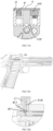
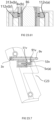
- the lock mechanism C4 is fixed on the grip A7 at the rear of the trigger A2 by mounting screw holes 93c on the fastening end 26c of the lock cover 2c.
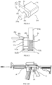
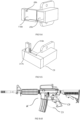
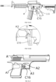
- the lock mechanism C4 may be used for a portable long-barrelled firearm A' or alike as shown in FIGs. 4.61 and 4.62 .
- the lock mechanism C4 is disposed in such a manner to interact with a trigger A'2 thereof.
- the basic structure of the lock mechanism C5 is similar to that of C3, and the lock core and the structure of a lock cover 2d are similar to C4. (The lock mechanisms C3, C4 and C5 are based on the same principle, however, differ in that where and how they are installed).
- the lock mechanism C5 may be used for a portable long-barrelled firearm A' or alike as shown in FIGs. 5.61 and 5.62 .
- the automatic spring-type lock mechanism C5 is disposed in such a manner to interact with a trigger A'2 thereof.
- the permanent magnet 30e is able to slide within the electromagnet installing slot 113e.
- the lock tongue spring 4 and the spring plate 32e are set in the spring slot 118e.
- the lock cover 2e is fixed on the upper part of the lock shell 1e.
- the controller may work on the current driver (not shown) on the handgun A, such that the electromagnet 5e(f) will instantly get electrified reversely for 10 ⁇ 100 ms, and instantaneously get the reverse current, produces a magnetic pole repelling the permanent magnet 30e, and then it produces a sufficient magnetic repulsion.
- the lock tongue actuator rod 314e is pushed out instantly by the repulsive force exerted by the lock tongue spring 4e and/or the magnetic repulsion as shown in FIG 6.4 , FIG 6.61 and FIG 6.62 .
- the firing pin A6 is blocked by the lock tongue actuator 3e, so the bullet cannot be hit, and the gun cannot be fired.
- FIGs 8.1 to 8.82 it provides an automatic spring-type lock mechanism C8, which is disposed at the end of the slide A4, which is adjacent with the hammer B7.
- the lock tongue actuator 3g corresponds the position B10 between the firing pin A6 and the hammer A5.
- the structure of the lock mechanism C8 is similar to that of C6, except for its installation position.
- two mounting plates 13g on the lock shell 1g are lengthened, comparing them with those of C7.
- the width between the two mounting plates 13g and the position where the gun mounted are matched.
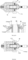
- the lock tongue hole 119g is set at the bottom of the lock tongue slot 112g (as shown in FIG. 8.3, FIG. 8.4, FIG. 8.5 , and FIG. 8.6 , respectively).
- the electromagnet 5g(f) is mounted on the upper end of the electromagnet installing slot 113g (see FIG. 8.5 ).
- the lock tongue actuator rod 314g extends out of the lock tongue hole 119g, and the lock tongue actuator rod 314g blocks the space B10 between the firing pin A6 and hammer A5 (as shown in FIG 8.1 , FIG 8.5 , FIG 8.71/8.72 ).
- the size or diameter of the lock tongue actuator rod 314g is sufficiently large to cover the firing pin A6 to keep the hammer A5 from striking the firing pin A6. So even when the hammer A5 strikes, the hammer A5 will only hit the lock tongue actuator rod 314g and will not hit the firing pin A6. The function of keeping the gun safe when the handgun A is not in use is realized.
- the electromagnet 5g(f) is electrified for 10 ⁇ 100 ms, and obtains a current, thus producing a magnet pole attracting the permanent magnet 30g.
- the permanent magnet 30g will overcome the elastic force exerted by the lock tongue spring 4g.
- the lock tongue spring 4g is compressed in a spring slot 118g by the spring plate 32g due to the force of the permanent magnet 30g and electromagnet 5g(f) (it is unnecessary to electrify the solenoid continuously for an extended period of time), and the lock tongue actuator rod 314g is retracted and locates in the lock tongue hole 119g.
- the lock tongue actuator rod 314g which blocks the hammer A5, retracts back.
- the hammer A5 is not blocked by the lock tongue actuator rod 314g and can strike the filing pin A6, thus, the gun A can be fired.
- the current to the electromagnet 5g(f) may be initiated by a current driver (not shown) which may be controlled by a controller (not shown).
- the controller may work on the current driver (not shown) on the handgun A, such that the electromagnet 5g(f) will instantly get electrified reversely for 10 ⁇ 100 ms, and instantaneously get the reverse current, thus producing a magnetic pole repelling the permanent magnet 30g, and then it produces a sufficient magnetic repulsion.
- the lock tongue actuator rod 314g is pushed out instantly by the repulsive force exerted by the lock tongue spring 4g and/or the magnetic repulsion within 150ms from when the controller detected the condition for locking the firing sequence.
- the lock tongue actuator rod 314g extends and blocks the space B10 between the firing pin A6 and the hammer A5 as shown in FIG 8.71 and 8.72 .
- the hammer A5 is blocked by the lock tongue, thus the gun cannot be fired.
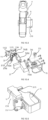
- a ninth preferred embodiment of the present invention provides a gear-type trigger lock mechanism C9 for a firearm or alike.
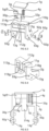
- the lock mechanism C9 includes a lock shell 1h, a lock cover 2h and a lock tongue actuator 3h, including a motor 5h(b), a driving gear 5h(d), an idler gear and/or gear set 5h(e) and a bar member 314h.
- the lock cover 2h has a motor placement slot 25h inside.
- the motor placement slot 25h receives the motor 5h(b), and the drive shaft of motor 5h(b) is connected with the driving gear 5h(d).
- the lock shell 1 h and/or the lock cover 2h have a lock cylinder cavity 11 h, which includes a gear mounting cavity 116h and a lock tongue slot 112h.
- the driving gear 5h(d) locates inside the gear mounting cavity 116h.
- the bar member 314h is mounted in lock tongue slot 112h, and the driving gear 5h(d) is engaged with the rack 316h.
- the idler gear and/or gear set 5h(e) can be added to increase the center distance.
- the driving gear 5h(d) is engaged with the idler gear and/or gear set 5h(e) and the idler gear and/or gear set 5h(e) is engaged with the rack 316h of the bar member 314h.
- the lock shell 1h or the lock cover 2h has an idler shaft 117h, and the idler gear and/or gear set 5h(e) is rotated with respect to the axis of the idler shaft 117h.
- the number of idler gear and/or gear set can be adjusted/changed according to center distance(s), rotation direction(s), and/or shifting(s).
- a first part of the bar member 314h has a stroke slot 315h, a first half part of the bar member 314h corresponding to the driving gear 5h(d) is the rack 316h, and a second half of the bar member 314h is a mounting surface 317h.
- the mounting surface 317h is matched with and mounted inside the lock tongue slot 112h, and the bar member 314h moves towards the direction of the lock tongue slot 112h.
- the stroke limiter 20h (a cylinder limits the position the bar member 314h) corresponding to the stroke slot 315h of the bar member 314h is set within the lock shell 1h or the lock cover 2h.
- the limiter locates within the stroke slot 315h.
- the lock cover 2h has a mounting base 7h(b), and the mounting base 7h(b) is disposed on the outer side of the motor placement slot 25h.
- the mounting base 7h(b) has mounting holes, and the gear-type lock mechanism C9 mechanism is mounted on the gun grip A7 via the mounting base 7h(b).
- a lock hole is provided on the trigger guard A3.
- the bar member 314h can extend through the lock hole in the trigger guard A3 when it protrudes.
- the bar member 314h passes through the lock hole and locates at the rear of the trigger A2.
- the bar member 314h blocks the backward stroke of the trigger A2 so that the trigger A2 cannot be pulled and the gun cannot be fired. This achieves the function of locking firearms when they are not in use.
- the motor 5h(b) When the gun is used normally, the motor 5h(b) is positively electrified for 10 to 100 ms, and the motor 5h(b) begins to rotate for driving the driving gear 5h(d) and the idler gear and/or gear set 5e to retract the bar member 314h into the lock tongue slot 112h.
- the bar member 314h retracts from the rear side of the trigger A2, then the motor 5h(b) does not need to be electrified.
- the backward stroke of the trigger A2 is not blocked and the gun is unlocked.
- the motor 5h(b) When an abnormal condition(s) is detected, the motor 5h(b) is electrified reversely for 10-100 ms, and the motor 5b starts to rotate the driving gear 5h(d) and the idler gear and/or gear set 5h(e) to extend the bar member 314h out from the lock tongue slot 112h.
- the bar member 314h moves to the rear side of the trigger A2, then the motor 5h(b) does not need to be electrified.
- the backward stroke of the trigger A2 is blocked and the gun is locked.
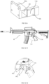
- the gear-type trigger lock C9 may be used for a portable long-barrelled firearm A' or alike as shown in FIGs. 9.61 and 9.62 .
- the gear-type trigger lock C9 is disposed in such a manner to interact with a trigger A'2 thereof.
- a gear-type trigger lock mechanism C10 which includes a lock shell 1i, a lock cover 2i and a lock tongue actuator 3i, including a motor 5i(b), a driving gear 5i(d), an idler gear and/or gear set 5i(e), and a bar member 314i.
- the lock cover 2i has a motor placement slot 25i inside.
- the motor placement slot 25i receives the motor 5i(b), and the drive shaft of motor 5i(b) is connected with a driving gear 5i(d).
- the lock shell 1i and/or the lock cover 2i have a lock cylinder cavity 11i, which includes a gear mounting cavity 116i and a lock tongue slot 112i.
- the driving gear 5i(d) locates inside the gear mounting cavity 116i.
- the bar member 314i is mounted in lock tongue slot 112i, and the driving gear 5i(d) is engaged with the rack 316i of the bar member 314i.
- the idler-wheel 5i(e) can be added to increase the center distance.
- the driving gear 5i(d) is engaged with the idler gear and/or gear set 5i(e) and the idler gear and/or gear set 5i(e) is engaged with the rack 316i of the bar member 314i.
- the lock shell 1i or the lock cover 2i has an idler shaft 117i, and the idler gear and/or gear set 5i(e) is rotated with respect to the axis of the idler shaft 117i.
- the number of idler gear and/or gear set can be adjusted/changed according to center distance(s), rotation direction(s), and/or shifting(s).
- a first part of the bar member 314h has a stroke slot 315i, a first half part of the bar member 314i corresponding to the driving gear 5i(d) is the rack 316i, and a second half of the bar member 314i is a mounting surface 317i.
- the mounting surface 317i is matched with and mounted inside the lock tongue slot 112i, and the bar member 314i moves towards the direction of the lock tongue slot 112i.
- the stroke limiter 20i (a cylinder limits the position of the bar member 314i) corresponding to the stroke slot 315i of the bar member 314i is set within the lock shell 1i or the lock cover 2i.
- the limiter locates within the stroke slot 315i.
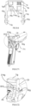
- the lock mechanism C10 is mounted on the grip A7 of the handgun A.
- the structure of the lock shell 1i, the driving gear 5i(d), the idler gear and/or gear set 5i(e), the shape and the installation of the bar member 314i are all the same as those of the lock mechanism C9, except for the installation position of the lock mechanism C10. While the shapes and structures of the lock shell 2i is different from those previously shown in the lock mechanism C9.
- the other side of the motor placement slot 25i stretches out of the mounting base 7i(b) and is attached to the clamp 7i.
- the shape of U-shaped clamp 7i matches the handgun A.
- the clamp 7i is fixed with the mounting base 7i(b) via the clamp connection plate 74i.
- the U-shaped clamp 7i is fastened to the grip A7 of the handgun A by fastening means, such as screws.
- the bar member 314i locates on the side of the trigger A2.
- the bar member 314i extends to the rear side of the trigger A2. Then the bar member 314i blocks the backward stroke of the trigger A2, so that the trigger A2 cannot be pulled and the gun cannot be fired.
- the function of locking the trigger when the gun is not in use can be realized.
- the motor 5i(b) When the gun is normally used, the motor 5i(b) is positively electrified for 10 to 100 milliseconds, and the motor 5i(b) begins to rotate and drives the driving gear 5i(d) the idler gear and/or gear set 5i(e), and to retract the bar member 314i in the lock tongue slot 112i.
- the bar member 314i which locates in the lock shell 1i, retracts from the rear side of the trigger A2, then the motor 5i(b) does not need to be electrified.
- the backward stroke of the trigger A2 is not blocked (released) and the trigger A2 is free to be pulled to fire the gun.
- the lock mechanism C10 may be used for a portable long-barrelled firearm A' or alike as shown in FIGs. 10.71 and 10.72 .
- the lock mechanism C10 is disposed in such a manner to interact with a trigger A'2 thereof.
- a gear-type trigger lock mechanism C11 which includes a lock shell 1j, a lock cover 2j and a lock tongue actuator 3j, including a motor 5j(b), a driving gear 5j(d), an idler gear and/or gear set 5j(e), and a bar member 314j.
- the lock cover 2j has a motor placement slot 25j inside.
- the motor placement slot 25j receives the motor 5j(b), and the drive shaft of motor 5j(b) is connected with a driving gear 5j(d).
- the lock shell 1j and/or the lock cover 2j has a lock cylinder cavity 11j, which includes a gear mounting cavity 116j and a lock tongue slot 112j.
- the driving gear 5j(d) locates inside the gear mounting cavity 116j.
- the bar member 314j is slidably mounted on a lock tongue slot 112j, and the driving gear 5j(d) is engaged with the rack 316j of the bar member 314j.
- the idler-wheel 5j(e) can be added to increase the center distance.
- the driving gear 5j(d) is engaged with the idler gear and/or gear set 5j(e) and the idler gear and/or gear set 5j(e) is engaged with the rack 316j of the bar member 314j.
- the lock shell 1 h or the lock cover 2j has an idler shaft 117j, and the idler gear and/or gear set 5j(e) is rotated with respect to the axis of the idler shaft 117j.
- the number of idler gear and/or gear set can be adjusted/changed according to center distance(s), rotation direction(s), and/or shifting(s).
- a first part of the bar member 314j has a stroke slot 315j, a first half part of the bar member 314j corresponding to the driving gear 5j(d) is the rack 316j, and a second half of the bar member 314j is a mounting surface 317j.
- the mounting surface 317j is matched with and mounted inside the lock tongue slot 112j, and the bar member 314h moves towards the direction of the lock tongue slot 112j.
- the stroke limiter 20j (a cylinder limits the position of the bar member 314j) corresponding to the stroke slot 315j of the bar member 314j is set within the lock shell 1j or the lock cover 2j.
- the limiter locates within the stroke slot 315j.
- the structure of the lock mechanism C11 is basically the same as that of the lock mechanism C9, except for the installation.
- the lock mechanism C11 structure of the embodiment is mounted on the grip A7 of the handgun A.
- the structure of the lock shell 1j, the shape and installation of the bar member 314j, the driving gear 5j(d) and bar member 314j are the same as those of the lock mechanism C9, except for the shape and the structure of the lock cover 2j.
- the motor placement slot 25j connects the mounting base 7j(b), and the gear-type lock mechanism C11 structure is mounted on the grip A7 of the handgun A via the mounting base 7j(b).
- the bar member 314j locates on one side of the trigger A2, and the bar member 314j locates at the rear end of the trigger A2 when it protrudes.
- the bar member 314j blocks the backward stroke of the trigger A2, so that the trigger A2 cannot be pulled and the gun cannot be fired. The function of locking the firearms when the firearms are not in use is realized.
- the motor 5j(b) When the gun is normally used, the motor 5j(b) is positively electrified for 10 to 100 ms, and the motor 5j(b) begins to rotate to drive the driving gear 5j(d) and the idler gear and/or gear set 5j(e), then to drive the rack 316j.
- the bar member 314j which locates in the lock shell 1j, retracts from the rear end of the trigger A2, then the motor 5j(b) does not need to be electrified.
- the backward stroke of the trigger A2 is not blocked (released) and the trigger A2 is free to be pulled to fire the gun.
- the lock mechanism C11 may be used for a portable long-barrelled firearm A' or alike as shown in FIGs. 11.71 and 11.72 .
- the lock mechanism C11 is disposed in such a manner to interact with a trigger A'2 thereof.
- a gear-type trigger lock mechanism C12 which includes a lock shell 1k, a lock cover 2k and a lock tongue actuator 3k.
- the lock tongue actuator 3k includes a motor 5k(b), a driving gear 5k(d), an idler gear and/or gear set 5k(e), and a bar member 314k.
- the lock cover 2k has a motor placement slot 25k inside. The motor placement slot 25k receives the motor 5k(b), and the drive shaft of the motor 5k(b) is connected with a driving gear 5k(d).
- the lock shell 1k and/or the lock cover 2k has a lock cylinder cavity 11k, which includes a gear mounting cavity 116k and a lock tongue slot 112k.
- the driving gear 5k(d) locates inside the gear mounting cavity 116k.
- the bar member 314k is mounted in lock tongue slot 112k, and the driving gear 5k(d) is engaged with the rack 316k of the bar member 314k.
- the idler-wheel 5k(e) can be added to increase the center distance.
- the driving gear 5k(d) is engaged with the idler gear and/or gear set 5k(e) and the idler gear and/or gear set 5k(e) is engaged with the rack 316k of the bar member 314k.
- the lock shell 1k or the lock cover 2k has an idler shaft 117k, and the idler gear and/or gear set 5k(e) is rotated with respect to the axis of the idler shaft 117k.
- the number of idler gear and/or gear set can be adjusted/changed according to center distance(s), rotation direction(s), and/or shifting(s).
- a first part of the lock tongue actuator 3k has a stroke slot 315k for slidably receiving the bar member 314k.
- a first half part of the bar member 314k which is corresponding to the driving gear 5k(d)/ the idler-wheel 5k(e) is the rack 316k, and a second half of the bar member 314k has a mounting surface 317k.
- the mounting surface 317k is matched with and mounted inside the lock tongue slot 112k, and the lock tongue actuator 3k moves towards the direction of the lock tongue slot 112k.
- the stroke limiter 20k (a cylinder limits the position the lock tongue actuator 3k) corresponding to the stroke slot 315k of the lock tongue actuator 3k is set within the lock shell 1k or the lock cover 2k.
- the limiter locates within the stroke slot 315k.
- the structure of the lock mechanism C12 is basically the same as that of the lock mechanism C9, except for the installation.
- the lock mechanism C12 of the present embodiment is installed at the rear of the slide A4 on the handgun A.
- the structure of the lock shell 1k, the shape and installation of the driving gear 5k(d) and bar member 314k are the same as those of the lock mechanism C9, but the shape and structure of the bar member 314k are different.
- the lock mechanism C12 controls the firing pin A6, and a firing pin circular slot B11 is set at the rear of the firing pin A6.
- the present embodiment includes a lock shell 1k and a lock cover 2k which are fixed together.
- the lock cover 2k has a motor placement slot 25k.
- a cover side gear mounting cavity 116k is set at the front end of the motor placement slot 25k.
- the cover side gear mounting cavity 116k has a stroke limiter 20k and an idler shaft 117k.
- the stroke limiter 20k locates inside the stroke slot 315k, and the idler shaft 117k is connected with the idler gear and/or gear set 5k(e).
- a motor 5k(b) is installed inside the motor placement slot 25k, and the drive shaft of the motor 5k(b) connects a driving gear 5k(d).
- the driving gear 5k(d) connects the bar member 314k via the idler gear and/or gear set 5k(e).
- a mounting base 7k(b) is on one side of the lock cover 2k, and it locates at the lower side of the motor placement slot 25k near the side gear mounting cavity 116k.
- the gear-type lock mechanism C12 is mounted via the mounting base 7k(b) at the rear of the gun slide A4.
- the bar member 314k has a stroke slot 315k. There is a semicircular fork 318k at the lower part of the bar member 314k. On one side of the bar member 314k, there exists a rack 316k. The idler gear and/or gear set 5k(e) meshes with the rack 316k.
- the gear-type lock mechanism C12 is mounted at the rear of the slide A4 on the handgun A.
- the semicircular fork 318k matches the firing pin circular slot B11 at the rear of the firing pin A6.
- the semicircular fork 318k is stuck at the firing pin circular slot B11.
- the bar member 314k fastens the firing pin A6 and the gun cannot be fired, as shown in FIG. 12.5 and FIG. 12.7 .
- the bar member 314k of the gear-type lock mechanism C12 structure is at the state of protruding, or namely, the semicircular fork 318k of the bar member 314k is stuck at the firing pin circular slot B11. Even if the hammer A5 hits the firing pin A6 and the firing pin A6 has the energy to hit the bullet, it will still be stuck and offset by the semicircular fork 318k, and cannot strike the bullet, thus the gun cannot be fired. This realizes the function of locking the firearms when it is not in use.
- the motor 5k(b) when the gun A is normally used, the motor 5k(b) is positively electrified for 10 ⁇ 100 ms, and a forward current signal drives the motor 5k(b) to rotate forward, driving the driving gear 5k(d). Then the driving gear 5k(d) rotates the idler gear and/or gear set 5k(e). In this way, the idler gear and/or gear set 5k(e) rotates and moves the rack 316k, so the bar member 314k retracts back with the rack 316k. Then the motor 5k(b) does not need to be electrified.
- the semicircular fork 318k of the bar member 314k rapidly retreats back from the firing pin circular slot B11. The firing pin A6 is not blocked by the bar member 314k and can hit bullets.
- the control motor 5k(b) rotates reversely when the lock needs to be closed.
- a gear-type trigger lock mechanism C13 includes a lock shell 1l, a lock cover 2l and a lock tongue actuator 3l, including a motor 5l(b), a driving gear 5l(d), an idler gear and/or gear set 5l(e), and a bar member 314l.
- the lock cover 2l has a motor placement slot 25l inside.
- the motor placement slot 25l receives the motor 5l(b), and the drive shaft of motor 5l(b) is connected with a driving gear 5l(d).
- the lock shell 1l and/or the lock cover 2l has a lock cylinder cavity 11l, which includes a gear mounting cavity 116l and a lock tongue slot 112l.
- the driving gear 5l(d) locates inside the gear mounting cavity 116l.
- the lock tongue actuator 3l is mounted in lock tongue slot 112l, and the driving gear 5l(d) is engaged with the rack 316l of the lock tongue actuator 3l.
- the idler-wheel 5l(e) can be added to increase the center distance.
- the driving gear 5l(d) is engaged with the idler gear and/or gear set 5l(e) and the idler gear and/or gear set 5l(e) is engaged with the rack 316I of the lock tongue actuator 3l.
- the lock shell 1l or the lock cover 2l has an idler shaft 117l, and the idler gear and/or gear set 5l(e) is rotated with respect to the axis of the idler shaft 117l.
- the number of idler gear and/or gear set can be adjusted/changed according to center distance(s), rotation direction(s), and/or shifting(s).
- a first part of the lock tongue actuator 3l has a stroke slot 315l for slidably receiving the bar member 314l.
- a first half part of the bar member 314l which is corresponding to the driving gear 5l(d) / the idler-wheel 5l(e) is the rack 316l, and a second half of the bar member 314l has a mounting surface 317l.
- the mounting surface 317l is matched with and mounted inside the lock tongue slot 112l, and the lock tongue actuator 3l moves towards the direction of the lock tongue slot 112l.
- the stroke limiter 20l (a cylinder limits the position the lock tongue actuator 3l) corresponding to the stroke slot 315l of the lock tongue actuator 3l is set within the lock shell 1l or the lock cover 2l.
- the limiter locates within the stroke slot 315l.
- the structure of the lock mechanism C13 is basically the same as that of the lock mechanism C9, except for the installation.
- the lock mechanism C13 is installed at the rear of the slide A4 of the handgun A.
- the basic structure of the lock shell 1l, the shape and installation of the driving gear 5l(d), the idler gear and/or gear set 5l(e), the bar member 314l are the same as those of the lock mechanism C9.
- the shape and structure of the lock tongue actuator 3l, the lock shell 1 and the lock cover 2l are partially different from the lock mechanism C9, C10, C11 or C12.
- the lock mechanism C13 is mounted at the rear of slide A4 of the handgun A.
- the lock mechanism C13 structure includes a lock shell 1l and a lock cover 2l, which are fastened together.
- the lock cover 2l has a motor placement slot 25l, and the lock shell 1l or the lock cover 2l has a gear mounting cavity 116l.
- the motor placement slot 25l has a motor 5l(b) inside.
- the drive shaft of the motor 5l(b) is connected with a driving gear 5l(d), and the driving gear 5l(d) connects the bar member 314l via the idler gear and/or gear set 5l(e).
- the bar member 314l has a stroke slot 315l.
- the gear mounting cavity 116l has a stroke limiter 20l.
- the stroke limiter 20l locates in the stroke slot 315l.
- the gear mounting cavity 116l has an idler shaft 117l, and the idler shaft 117l connects the idler gear and/or gear set 5l(e).
- the bar member 314l has a rack 316l on one side. The idler gear and/or gear set 5l(e) meshes with the rack 316l.
- the lower end of the lock shell 1l has a fixing clamp plate 13l.
- the lock mechanism C13 is mounted on the rear of slide A4 of the handgun A via a fixing clamp plate 13l.
- the bar member 314l blocks between the firing pin A6 and the hammer A5. When the bar member 314I extends, it prevents the hammer A5 from striking the firing pin A6, so the gun cannot be fired.
- a fourteenth preferred embodiment of the present invention provides a semi-automatic electromagnetic telescoping lock mechanism C14, which includes a lock shell 1m, a lock cover 2m and a lock tongue actuator 3m, including a lock tongue spring 4m, an electromagnet 5m(f), a lock tongue limit spring 5m(g), lock tongue limit block 5m(h) and a bar member 314m.
- the lock mechanism C14 is mounted on handgun A via the lock shell 1m.
- the lock shell 1m and / or lock cover 2m defines a lock tongue groove 112m and an electromagnet groove 113m.
- the lock tongue groove 112m has an opening / lock tongue extending hole 28m at one end thereof, that faces to the rear of trigger A2.
- the bar member 314m is slidably engaged with the lock tongue groove 112m and is biased by the lock tongue spring 4m, which is located at the closed end (opposite to the lock tongue extending hole 28m) of the lock tongue groove 112m.
- the first clamp slot 321m and the second clamp slot 321 m(a) are located on the bar member 314m.
- the lock shell 1m has lock handle sliding groove 320m(a); and the position of the lock shell 1m is corresponding with the lock tongue actuator 3m.
- the lock tongue reset handle 320m is in communication with the bar member 314m to retract the bar member 314m.
- the lock tongue limit block 5m(h) is embedded in the first clamp slot 321m or the second clamp slot 321m(a).
- the electromagnet (or push-pull solenoid) 5m(f), the lock tongue limit spring 5m(g), and the lock tongue limit block 5m(h) are disposed inside the electromagnetic grove 113m.
- the lock tongue limit block 5m(h) is designed to correspond with a first clamp slot 321m and a second clamp slot 321m(a) on the bar member 314m.
- the electromagnet 5m(f) may be driven by a driver (not shown), which may be controlled by a controller (now shown).
- the guard slot 12m is on the side opening of lock shell 1m.
- the guard slot 12m is designed to match with the trigger guard A3.
- a clamp plate 7m is installed on the side of the lock cover 2m.
- the second guard slot 22m is built on top of the clamp plate 7m and corresponds to the guard slot 12m. the clamp plate 7m is screwed on the lock cover 2m.
- the second guard slot 22m and the guard slot 12m form a clipped-shape, which correspond with the trigger guard A3 in order to allow the lock mechanism 14 to clamp on the trigger guard A3 tightly.
- the bar member 314m may be in cylindrical shape; however, the structure of the bar member 314m may be in other shapes, as long as it facilitates blocking the trigger A2 from being pulled.
- the lock mechanism C14 is installed below the trigger guard A3 of the handgun A.
- a safety sensing control system (not shown) may be installed on the handgun A to control the lock mechanism C14.
- a hole is drilled at the bottom of the trigger guard A3 of the handgun A to allow the bar member 314m to go through the drilled hole.
- the lock mechanism C14 may be used for a portable long-barrelled firearm A' or alike as shown in FIGs. 14.51 and 14.52 .
- the semi-automatic lock mechanism C14 is disposed in such a manner to interact with a trigger A'2 thereof.
- a semi-automatic lock mechanism C15 which includes a lock shell 1n, lock cover 2n and a lock tongue actuator 3n, including a lock tongue spring 4n, an electromagnet 5n(f), a lock tongue limit spring 5n(g), a lock tongue limit block 5n(h) and an arc member 314n.
- the lock mechanism C15 is mounted on the handgun A via lock shell 1n.
- the lock shell 1n and/or lock cover 2n defines a lock tongue groove 112n and an electromagnet groove 113n.
- the lock tongue groove 112n has an opening / lock tongue extending hole 28n at one end thereof, that faces to the rear of trigger A2.
- the arc member 314n is slidably engaged with the lock tongue groove 112n and is biased by the lock tongue spring 4n, which is located at the closed end (opposite to the lock tongue extending hole 28n) of the lock tongue groove 112n.
- the first clamp slot 321n and the second clamp slot 321n(a) are located on the arc member 314n.
- the lock shell 1n has a lock handle sliding groove 320n(a); and the position of the lock shell 1n is corresponding with the arc member 314n.
- a lock tongue reset handle 320n is in communication with the arc member 314n to retract the arc member 314n.
- the lock tongue limit block 5n(h) is embedded in the first clamp slot 321n or the second clamp slot 321n(a).
- the electromagnet (or push-pull solenoid) 5n(f), the lock tongue limit spring 5n(g), and the lock tongue limit block 5n(h) are disposed inside the electromagnetic grove 113n.
- the lock tongue limit block 5n(h) is designed to correspond with the first clamp slot 321n and the second clamp slot 321n(a) located on the arc member 314n.
- the electromagnet 5n(f) may be driven by a driver (not shown), which may be controlled by a controller (now shown).
- the lock tongue groove 112n is designed to be shaped in correspondence with the arc shape of the arc member 314n.
- the lock shell 1n and/or lock cover 2n define the lock tongue groove 112n and the electromagnet groove 113n.
- the guard slot 12n is defined by an opening surface of the lock shell 1n and lock cover 2n.
- the second guard slot 22n is defined by the clamp plate 7n and it is designed to match with the guard slot 12n.
- the clamp plate 7n is clipped on top of the lock shell 1n and lock cover 2n.
- the guard slot 12n and the second guard slot 22n correspond to the outer shape of the trigger guard A3 for clamping thereto, thus the lock mechanism C15 may be clamped to the trigger guard A3.
- lock tongue actuator 3n locks, due to its unique shape, it extends behind the trigger from the side in order to prohibit pulling trigger A2.
- the lock mechanism C15 may be used for a portable long-barrelled firearm A' or alike as shown in FIGs. 15.51 and 15.52 .
- the lock mechanism C15 is disposed in such a manner to interact with a trigger A'2 thereof.
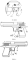
- a semi-automatic lock mechanism C16 which includes a lock shell 1o, lock cover 2o and a lock tongue actuator 3o, including a lock tongue spring 4o, an electromagnet 5o(f), a lock tongue limit spring 5o(g), lock tongue limit block 5o(h) and a bar member 314o.
- the lock mechanism C16 is mounted on a handgun A via the U-shaped clamp plate 7o.
- the lock shell 1o and/or lock cover 2o defines a lock tongue groove 112o and an electromagnet groove 113o.
- the lock tongue groove 112o has an opening / lock tongue extending hole 28o at one end thereof, that faces to the rear of the trigger A2.
- the bar member 314o is slidably engaged with the lock tongue groove 112o and is biased by the lock tongue spring 4o, which is located at the closed end (opposite to the lock tongue extending hole 28o) of the lock tongue groove 112o.
- the first clamp slot 321o and the second clamp slot 321o(a) are located on the bar member 314o.
- the lock shell has lock handle sliding groove 320o(a); and the position of the lock shell 1o is corresponding with the lock tongue actuator 3o.
- the lock tongue reset handle 320o connects to the bar member 314o.
- the lock tongue limit block 5o(h) is embedded in the first clamp slot 321o or the second clamp slot 321o(a).
- the electromagnet (or push-pull solenoid) 5o(f), lock tongue limit spring 5o(g), and lock tongue limit block 5o(h) are disposed inside the electromagnetic grove 113o.
- the lock tongue limit block 5o(h) is designed to correspond with a first clamp slot 321o and a second clamp slot 321o(a) on the bar member 314o.
- the electromagnet 5o(f) may be driven by a driver (not shown), which may be controlled by a controller (not shown).
- the structure of the lock mechanism C16 is similar to that of the lock mechanism C13, except the installing method and position.
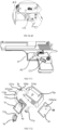
- the clamp plate 7o is designed in a U-shaped and the area inside 76o, which is used to hold gun grip A7.
- the clamp connection plate 74o is built on the inner side of the U-shaped clamp plate 7o, the lock shell 1o and lock cover 2o is installed on the clamp connection plate 74o; and the lock mechanism C16 can be installed on the gun grip A7 through the U-shaped clamp plate 7o.
- the lock mechanism C16 is adjustable by adjusting a screw(s) 77o. Screws 77o are used to connect the U-shaped clamp plate 7o with lock shell 1o and lock cover 2o to improve its stability and safety.
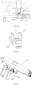
- the lock mechanism C16 may be used for a portable long-barrelled firearm A' or alike as shown in FIGs. 16.41 and 16.42 .
- the semi-automatic lock mechanism C16 is disposed in such a manner to interact with a trigger A'2 thereof.
- a semi-automatic lock mechanism C17 which includes a lock shell 1p, a lock cover 2p and a lock tongue actuator 3p, including a lock tongue spring 4p, a push-pull solenoid 5p (which is equivalent to use of a combination of electromagnet, lock tongue limit spring and lock tongue limit block as used in C14, C15, C16, C18, etc.) and an arc member 314p.
- the lock mechanism C17 is mounted on the handgun A via U-shaped clamp plate 7p.
- the lock shell 1p and/or lock cover 2p defines a lock tongue groove 112p and an electromagnet groove (not shown).
- the lock tongue groove 112p has an opening / lock tongue extending hole 28p at one end thereof, that faces to the rear of trigger A2.
- the arc member 314p is slidably engaged with the lock tongue groove 112p and is biased by the lock tongue spring 4p, which is located at the closed end (opposite of the lock tongue extending hole 28p) of the lock tongue groove 112p.
- the first clamp slot 321p and the second clamp slot 321p(a) are located on the arc member 314p.
- the lock cover 2p has a lock handle sliding groove 320p(a); and the position of the lock shell 1p is corresponding with the arc member 314p.
- the lock tongue reset handle 320p is in communication with the arc member 314p to retract the arc member 314p.
- the iron core 51p operably engages with the first clamp slot 321p or the second clamp slot 321p(a).
- the push-pull solenoid 5p is disposed inside the electromagnetic grove (not shown).
- the iron core 51p is designed to correspond/operate (engage or release) with the first clamp slot 321p and the second clamp slot 321p(a) located on the arc member 314p.
- the push-pull solenoid 5p may be driven by a driver (not shown), which may be controlled by a controller (not shown).
- the lock mechanism C17 is designed to be installed on the firearm grip A7, along with the U-shaped clamp plate 7p, including lock shell 1p and lock cover 2p.
- the arc-shaped lock tongue groove 112p is welded on the lock shell 1p.
- the shape of the arc-shaped member 314p is matched with that of the lock tongue groove 112p.
- the shape of the second sliding groove 17p which is locating on the lock tongue groove 112p, is designed to match with the lock handle sliding groove 320p(a), where lock tongue reset handle 320p is in communication with the arc member 314p.
- the shape of iron core 51p is matched with the second clamp slot 321p(a) and the first clamp slot 321p.
- the lock shell 1p and lock cover 2p are installed on the side of the U-shaped clamp plate 7p.
- the lock mechanism C17 is mounted on the firearm grip A7 via the U-shaped clamp plate.
- the lock tongue actuator 3p extends the arc member 314p to lock the handgun A
- the arc member 314p extends behind the trigger A2 from the side of the handgun A.
- the lock tongue actuator 3p is disposed inside the lock cover 2p;
- the push-pull solenoid 5p has similar capabilities as the composing elements of the electromagnetic telescoping lock mechanism: a combination of electromagnet, lock tongue limit spring and lock tongue limit block as discussed in other mechanical locks C14, C15, C16 and C18.
- This lock mechanism C17 is screwed on the firearm grip A7 via the U-shaped clamp plate 7p. The position thereof is adjustable.
- the principle of the operation in the semi-automatic lock mechanism C17 is similar to the semi-automatic lock mechanism C15; whereas, the lock mechanism is fixed on the grip A7 and the lock tongue actuator 3p extends behind the trigger A2 from the side to prohibit pulling the trigger A2 in its locking position.
- the lock mechanism C17 may be used for a portable long-barrelled firearm A' or alike as shown in FIGs. 17.51 and 17.52 .
- the lock mechanism C17 is disposed in such a manner to interact with a trigger A'2 thereof.
- a semi-automatic lock mechanism C18 which includes a lock shell 1q, a lock cover 2q and a lock tongue actuator 3q, including a lock tongue spring 4q, an electromagnet 5q(f), a lock tongue limit spring 5q(g), lock tongue limit block 5q(h) and a bar member 314q.
- the lock mechanism C18 is mounted on handgun A via lock shell 1q and/or lock cover 2q.
- the lock shell 1q and/or lock cover 2q define a lock tongue groove 112q and an electromagnet groove 113q.
- the lock tongue groove 112q has an opening / lock tongue extending hole 28q at one end thereof, that faces to the rear of trigger A2.
- the bar member 314q is slidably engaged the lock tongue groove 112q and is biased by the lock tongue spring 4q, which is located at the closed end (opposite to the lock tongue extending hole 28q) of the lock tongue groove 112q.
- the first clamp slot 321q and the second clamp slot 321q(a) are located on the bar member 314q.
- the lock shell has lock handle sliding groove 320q(a) and the position of the lock shell is corresponding with lock tongue actuator 3q.
- the lock tongue reset handle 320q is in communication with the bar member 314q to retract the bar member 314q.
- the lock tongue limit block 5q(h) is embedded in the first clamp slot 321q or the second clamp slot 321q(a).
- the electromagnet (or push-pull solenoid) 5q(f), lock tongue limit spring 5q(g), and lock tongue limit block 5q(h) are disposed inside the electromagnetic grove 113m.
- the lock tongue limit block 5q(h) is designed to correspond with the first clamp slot 321q and the second clamp slot 321q(a) located on the lock tongue actuator 3q.
- the electromagnet 5q(f) may be driven by a driver (not shown), which may be controlled by a controller (not shown).
- the structure of the lock mechanism (C18) is similar to those of C14 and C16, besides the installing method and position.
- the lock shell 1q is interlocked with the lock cover 2q.
- the clamp plate 7q(b) is installed on the mounting surface of lock shell 1q and the lock cover 2q.
- the lock mechanism C18 is installed on the grip A7 of the handgun A via clamp plate 7q(b).
- the bar member 314q extends behind the trigger A2 from the side to prohibit pulling the trigger in its locking position.
- the lock mechanism C18 may be used for a portable long-barrelled firearm A' or alike as shown in FIGs. 18.51 and 18.52 .
- the lock mechanism C18 is disposed in such a manner to interact with a trigger A'2 thereof.
- the lock mechanism C19 provides a semi-automatic lock mechanism C19, which has a structure similar to that of the lock mechanism C17.
- the lock mechanism C19 comprises a lock shell 1r, and a lock tongue actuator 3r, including a lock tongue spring 4r, a push-pull solenoid 5r and an arc member 314r.
- a lock tongue groove 112r is designed to be matched with lock tongue actuator 3r to be arc-shaped, partially welded on lock shell 1r.
- the second sliding slot numbered as 17r is designed on the lock tongue groove 112r.
- An electromagnetic telescoping mechanism is composed by the push-pull solenoids 5r, which is installed on the electromagnet groove 113r located inside lock shell 1r.
- the lock shell 1r is block-shaped and screwed on grip A7 via thickened guard B13. By utilizing the space created by the thickened guard B13, a portion of the lock mechanism C19 or additional features / functions (such as a printed circuit board therefor or other) may be placed therein.
- the arc member 314r extends from one side of the gun to the backside of trigger A2 at full extension position. The arc member 314r extends behind the trigger A2 from the side to prohibit pulling the trigger A2 in its locking position.
- the locked position and unlocked position of the arc member 314r are carried out in the same manner as shown in the lock mechanism C17.
- the push-pull solenoid 5r may be driven by a driver (not shown), which may be controlled by a controller (not shown).
- the lock tongue limit block 5m(h)/5n(h)/5o(h)/(not shown in C17)/5q(h)/(not shown in C19), or the iron core (not shown in C14)/(not shown in C15)/(not shown in C16)/51p/(not shown in C18)/51r is pointing to the second clamp slot 321m(a)/321 n(a)/321o(a)/321 p(a)/321q(a)/321r(a).
- the lock tongue limit block 5m(h)/5n(h)/5o(h)/(not shown in C17)/5q(h)/(not shown in C19) or the iron core (not shown in C14)/(not shown in C15)/(not shown in C16)/51p/(not shown in C18)/51r is being extended onto the second clamp slot 321 m(a)/321 n(a)/321o(a)/321p(a)/321q(a)/321r(a).
- the bar member 314m/314n/314o/314p/314q/314r is extended to block a firing sequence of the handgun A.
- the bar member 314m reaches to the rear side of the trigger A2 from the bottom portion of the trigger guard A3 to prevent the movement of the trigger from being pulled.
- the bar member 314n/314o/314p/314q/314r reaches to the rear side of the trigger A2 laterally or from the side to prevent the movement of the trigger A2 from being pulled.
- the purpose is substantially the same for the bar member 314m/314n/314o/314p/314q/314r, which is to reach to the rear side of the trigger A2 such that the bar member 314m/314n/314o/314p/314q/314r prevents the trigger A2 from being pulled (thus blocks the firing sequence of the handgun A).
- the electromagnet 5m(f)/5n(f)/5o(f)/(not shown in C17)/5q(f)/(not shown in C19) may be electrified, in which the magnetic force caused by the electromagnet 5m(f)/5n(f)/5o(f)/(not shown in C17)/5q(f)/(not shown in C19) allows the lock tongue limit block 5m(h)/5n(h)/5o(h)/(not shown in C17)/5q(h)/(not shown in C19) to resist the elastic force caused by the limit spring 5m(g)/5n(g)/5o(g)/(not shown in C17)/5q(g)/(not shown in C19), resulting the limit block 5m(h)/5n(h)/5o(h)/(not shown in C17)/5q(h)/(not shown in C19) to eject from the second clamp slot 321m(a)/321 n(a)/321o(a)/321p(
- the bar member 314m/314n/314o/314p/314q/314r can be moved freely.
- the lock tongue reset handle 320m/320n/320o/320p/320q/320r can then be pulled manually against the elastic force caused by spring 4m/4n/4o/4p/4q/4r.
- the bar member 314m/314n/314o/314p/314q/314r is then pulled back into the lock tongue groove 112m/112n/112o/112p/112q/112r.
- the lock tongue limit block 5m(h)/5n(h)/5o(h)/(not shown in C17)/5q(h)/(not shown in C19) is being bounced into the first clamp slot 321 m/321 n/321o/321p/321q/321r by the elastic force caused by the limit spring 5m(g)/5n(g)/5o(g)/(not shown in C17)/5q(g)/(not shown in C19); or as the push-pull solenoid (not shown in C14)/(not shown in C15)/(not shown in C16)/5p/(not shown in C18)/5r is controlled in such a way that the iron core (not shown in C14)/(not shown in C15)/(not shown in C16)/51 p/(not shown in C18
- the electromagnet 5m(f)/5n(f)/5o(f)/(not shown in C17)/5q(f)/(not shown in C19) may be electrified in order to counter the force exerted by the limit spring 5m(g)/5n(g)/5o(g)/(not shown in C17)/5q(g)/(not shown in C19) just enough to pull the lock tongue limit block 5m(h)/5n(h)/5o(h)/(not shown in C17)/5q(h)/(not shown in C19) out from the first clamp slot 321m/321n/321o/321p/321q/321r located on the bar member 314m/314n/314o/314p/314q/314r; or as the push-pull solenoid (not shown in C14)/(not shown in C15)/(not shown in C16)/5p/(not shown in C18)/5r is controlled to retract the iron core (not shown in C14)/(not shown in C15)
- the electromagnet 5m(f)/5n(f)/5o(f)/(not shown in C17)/5q(f)/(not shown in C19) or the push-pull solenoid (not shown in C14)/(not shown in C15)/(not shown in C16)/5p/(not shown in C18)/5r will be electrified shortly, the limit block 5m(h)/5n(h)/5o(h)/(not shown in C17)/5q(h)/(not shown in C19) or the iron core (not shown in C14)/(not shown in C15)/(not shown in C16)/51p/(not shown in C18)/51r ejects from the second clamp slot 321m(a)/321 n(a)/321o(a)/321 p(a)/321q(a)/321 r(a); meanwhile, the lock tongue reset handle 320m/320n/320o/320p/320q/320r should be pulled
- the mechanical part of the lock actuator can be composed by push-pull solenoid or servo motor accordingly.
- the operation principle shall be the same.
- a control system may directly control the servo motor driver.
- FIGs. 20.1 to 20.6 it provides a pull-rod style trigger lock mechanism C20.
- the lock mechanism C20 includes a lock shell 1s, a lock cover 2s, a bar member 314s, a pull-rod 32s, a pull-rod screw 32s(a), a pull-rod screw hole 32s(b), a lock tongue spring 4s and a self-holding solenoid 5s(a).
- the lock shell 1s has a lock core cavity 11s.
- a lock core cavity plate 111s separates the lock core cavity 11s into two cavities: a first pull-rod cavity 11s(a) and a second pull-rod cavity 11s(b).
- the bar member 314s comprises a conical frustum 34s, which is disposed one end that connects to the pull-rod 32s, and the bar member 314s is slidably engaged with the first pull-rod cavity 11s(a), slidable along a moving path of the trigger A2.
- the bar member 314s comprises a trigger clamp 31s for receiving the trigger A2 of the handgun A.
- the pull-rod 32s is slidably engaged with the second pull-rod cavity 11s(b).
- the pull-rod 32s comprises a position limiter 33s for limiting the range of the movement of the pull-rod 32s within the second pull-rod cavity 11s(b).
- the position limiter 33s has a diameter larger than the cavity 111s(a) of the lock core cavity plate 111s, while the diameter of the pull-rod 32s is sufficiently correspond to or smaller than the diameter of the cavity 111s(a) such that the pull-rod 32s freely slides through the cavity 111s(a).
- the opposite end of the pull-rod 32s is attached to the conical frustum 34s of the bar member 314s.
- the diameter of the conical frustum 34s is larger than that of the cavity 111s(a) of the lock core cavity plate 111s, such that the range of the movement of the bar member 314s is limited by the lock core cavity plate 111s.
- the position limiter 33s may be welded with to the pull-rod 32s.
- the lock tongue spring 4 embraces the pull-rod 32s and biases the position limiter 33s away from the lock core cavity plate 111s.
- the self-holding solenoid 5s(a) is set perpendicular to the sliding direction of the bar member 314s.
- the iron core 51s on the self-holding solenoid 5s(a) extends through the lock core hole 18s on the lock shell 1s and reaches onto the bar member 314s, the conical frustum 34s or the pull-rod 32s.
- the self-holding solenoid 5s(a) is disposed in the solenoid shell 6s.
- the trigger clamp 31s engages with the trigger A2 firmly.
- the lock shell 1s comprises two parts: the upper lock shell 1s and lower lock cover 2s, which are interlocked with each other.
- the upper and lower lock shells 1s and 2s, respectively, have corresponding/mating shapes and structures.
- Two mounting clamp plates 13s are provided on the lock shell 1s to form a clamp plate slot 14s.
- the lock mechanism C20 is clamped at the front part of the trigger guard A3 with the clamp plate slot 14s as shown in FIG 20.1 .
- the clamp plate slot 14s can be replaced by proper Picatinny rails.
- the self-holding solenoid 5s(a) may be electrified to allow the iron core 51s to be extended outward onto the bar member 314s, the conical frustum 34s or the pull-rod 32s (depending on when the self-holding solenoid 5s(a) is driven in relation to a firing sequence of the handgun A). If the iron core 51s lands on the conical frustum 34s as shown in FIG.
- the pull-rod 32s will eventually move back to its original position under the joint force exerted by the lock tongue spring 4s and the cone at one side of conical frustum 34s, allowing the conical frustum 34s to be settled between the iron core 51s and lock core cavity plate 111s. If the iron core 51s extends onto the bar member 314s, the conical frustum 34s is between the iron core 51s and the lock core cavity plate 111s, thus the handgun A is locked. If the iron core 51s lands on the pull-rod 32s, as shown in FIG.
- the lock mechanism C21 comprises a self-holding solenoid 5t(a) and a lock tongue actuator 3t.
- the self-holding solenoid 5t(a) locates in the electromagnet installing slot 113t.
- the electromagnet installing slot 113t receives a lock cover 2t for housing the self-holding solenoid 5t(a).
- the self-holding solenoid 5t(a) has a round end iron core 52t, which can extend into the lock tongue slot 112t through a hole on the partition plate 94t.
- the direction of the sliding movement of the lock tongue actuator 3t is perpendicular to that of the iron core 52t in the lock tongue slot 112t.
- One end of the lock tongue actuator 3t has an arc surface 313t attaching with the round end of the iron core 52t, and the other end of the lock tongue actuator 3t has a lock tongue actuating lever 314t, which is biased by a lock tongue spring 4t.
- the grip A7 of the gun frame A1 has a frame spring slot B2, and a lock hole B1 locates inside the frame spring slot B2.
- the lock hole B1 corresponds to the limit hole B6 on the trigger lever B5.
- the lock shell 1t of the lock mechanism C21 instead of the grip panel A8 is mounted on the grip A7.
- the lock cover 2t is attached between the grip A7 of handgun A and the self-holding solenoid 5t(a), and one end of the lock tongue spring 4t locates in the frame spring slot B2 pressing against the gun frame A1.
- the lock tongue actuating lever 314t of the lock tongue actuator 3t enters through the lock hole B1 and to the limit hole B6.
- the lock tongue actuating lever 314t corresponds to the lock hole B1 and the limit hole B6.
- the self-holding solenoid 5t(a) may be electrified for 10 to 100 ms (the solenoid 5t(a) itself may have self-holding function, the solenoid 5t(a) may be able to hold its position). Obtaining instantaneous currents, the round iron core 52t instantaneously exits from the lock tongue slot 112t.. Then the tongue lock spring 4t is released, such that the lock tongue actuating lever 314t exits from the limit hole B6 by the elastic force. The trigger A2 is no longer blocked and free to be pulled, and the handgun A can fire.
- the gun frame A1 has a lock hole B1.
- the trigger lever B5 corresponds to a limit hole B6 at the lock hole B1.
- the iron core 51u corresponds to the frame spring slot B2, and the lock tongue actuator 3u corresponds to the lock hole B1 and the limit hole B6.
- FIG 22.21 When the handgun A is not in use, the locking state of the lock mechanism C22 is shown in FIG 22.21 .
- the iron core 51u is at the normal stretching position.
- the iron core 51u extends through the lock cover 2u and the lock hole B1 on the gun frame A1 and stretches into the limit hole B6 on the trigger lever B5.
- the trigger A2 is locked and cannot be pulled, so that the handgun A cannot be pulled.
- the purpose of keeping the gun safe when it is not in use is achieved.
- the lock shell 1w defines front, rear, right, left, top and bottom, and has two mounting clamp plates 13w on the right and left sides of the lock shell 1w.
- the two clamp plates 13w define a clamp plate slot 14w on top of the lock shell 1w.
- the lock shell 1w is fixed on the handgun A through the mounting holes.
- a lock core cavity 11w is located on the bottom of the lock shell 1w.
- a string hole 16w is located on the front of the lock shell 1w connecting through to the lock core cavity 11w.
- the tapeline disk 8w is operably mounted in the lock tongue cavity 11w.
- One end of the lock tongue 3w is attached to and twined around a wire slot 83w defined on the tapeline disk 8w.
- the other end of the string i.e. the lock tongue 3w
- a round convex plate 19w is situated at the center of the lock core cavity 11w.
- a lock tongue spring axle 191w is a shaft member, which is located at the axis of the round convex plate 19w.
- the lock tongue spring axle 191w defines a slot 192w locates along the lengthwise of the lock tongue spring axle 191w.
- the lock tongue spring 4w is mounted within the spring mounting cavity 84w in the tapeline disk 8w.
- the outer ring hook 42w of the lock tongue spring 4w is fixed within the disk slot 82w.
- the fixed end of the spring 41w is inserted in the slot 192w.
- the lock tongue spring 4w is mounted within the spring mounting cavity 84w of the tapeline disk 8w.
- the tapeline disk 8w has a tapeline disk hole 81w, which corresponds to the lock cover hole 211w.
- the self-holding solenoid 5w(a) is an actuator, that comprises and actuates an iron core 51w, the iron core 51w corresponds to the tapeline disk hole 81w.
- the iron core 51w is arranged to pass through the lock cover hole 211w and to the tapeline disk hole 81w.
- the solenoid shell 6w covers the self-holding solenoid 5w(a), and connects to the lock cover 2w.
- the initial state of the iron core 51w extends outward and reaches to the tapeline disk hole 81w, such that the iron core 51w impedes and blocks the movement of the tapeline disk 8w and, thus, the trigger A2 cannot be pulled.
- a Picatinny rail or similar rail interface system can be used to replace the clamp plate slot 14w in order to hold the related components onto the handgun A.
- High strength soft strings, as well as the soft steel strings with low elastic and memory steel strings may be selected to use as lock tongue 3w.
- the tapeline disk 8w can rotate around the axis of the round convex plate 19w on the lock shell 1w and then is repositioned by the force of lock tongue spring 4w, which is substantially similar to the mechanism of a tape measure.
- This tech solution needs a tapping at the front end of trigger guard A3 through which the lock tongue 3w passes and connects the trigger A2 and gets fastened.
- the lock mechanism C24 may be clamped on other types of firearms or portable weapons, such as cross bows. Preference should be given to the self-holding solenoid 5w(a) when selecting the solenoids.
- the iron core 51w in the self-holding solenoid 5w(a) of the mechanical lock C24 retracts and releases the tapeline disk hole 81w, allowing the tapeline disk 8w to rotate freely.
- the lock tongue spring 4w and the lock tongue 3w make free reciprocating motion and the trigger A2 can be moved freely such that the handgun A can be fired. Once the handgun A fires, the lock tongue spring 4w returns to its original position and drives the tapeline disk 8w return to its original position.
- the iron core 51w, the lock cover hole 211w and the tapeline disk hole 81w share the same axis, so the handgun A is at unlocked state and can be fired.
- FIG 25.1 to 25.4 it provides a box-style lock mechanism C25, which may be installed on a handgun A, around and about a trigger guard A3 of the handgun A.
- the lock mechanism C25 includes a lock shell 1x, a lock cover 2x, a lock tongue 3x, a mounting shell 61x, an electromagnet 5x(f) and a permanent magnet 30x.
- the lock tongue 3x defines a finger window 36x, and the finger window 36x corresponds to a finger hole 15x defined on the lock shell 1x.
- the electromagnet 5x(f) is housed in the mounting shell 61x and is fastened at one end of the lock shell 1x.
- the electromagnet 5x(f) is an actuator, and is arranged to cooperate with the permanent magnet 30x.
- the lock cover 2x and lock shell 1x are arranged to encase the trigger guard A3 from its sides, and the box-style lock mechanism C25 is fastened on the trigger guard A3 by using fastening means, such as mounting screws 92x.
- the guard clamp slot 12x locates at a bottom part of the lock shell 1x.
- the lock cover 2x is symmetrical to / corresponds to the lock shell 1x.
- the lock cover 2x further comprises a second guard clamp slot 22 that corresponds to the guard clamp slot 12x, thus, when the lock shell 1x and the lock cover 2x mates to encase the trigger guard A2 from its sides, the guard clamp slot 12x also corresponds and mates with the second guard clamp slot 22x.
- the mounting shell 61x comprises fixing ears 611x, defining fixing holes 612x.
- Fastening means such as shell fixing screws 613x may be used to mount the mounting shell 61x on the lock shell 1x.
- lock tongue slots 112x there are two lock tongue slots 112x, symmetrically set at the top and bottom ends of the inner side of the lock shell 1x.
- the lock tongue 3x engages with and slides along the lock tongue slots 112x.
- finger window 36x there are two positions of the finger window 36x, which are corresponded with finger hole 15x.
- the finger hole 15w will be placed in finger window 36w. Whereas, the finger hole 15w locates outside of the finger window 36w under locking position.
- the block 614x is used for positioning and guiding of the mounting shell 61x in reference to the lock shell 1x.
- the block 614x is in touch with the front-end surface of the lock shell 1x.
- the lock mechanism C25 is controlled to have the pole of the electromagnet 5x(f) to be the opposite to the pole of the permanent magnet 30x, causing to have the electromagnet 5x(f) and the permanent magnet 30x are attracted each other.
- the lock tongue 3x is then, because of the attraction force, drawn toward the electromagnet 5x(f).
- the finger hole 15x is, then, blocked by the lock tongue 3x, preventing a finger from entering through finger hole 15x and the finger window 36x. Accordingly, the trigger A2 inside the trigger guard A2 is now blocked.
- the electromagnet 5x(f) When the handgun A is allowed for operation / use, the electromagnet 5x(f) is controlled have a magnetic polar to be the same as that of the permanent magnet 30x, thus electromagnet 5x(f) pushed the permanent magnet 30x away. In this condition, electromagnet 5x(f) pushes the lock tongue 3x away swiftly, for example, within 100 milliseconds, allowing the finger hole 15x be opened thus allowing a finger to touch the trigger A2 inside the trigger guard A3, and the handgun A can be fired.
- the electromagnet 5x(f) may be controlled to drive the permanent magnet 30 to be toward each other, such that lock tongue 3x to block the finger hole 15 with the lock tongue 3x. Accordingly, the trigger A2 cannot be touched and the handgun A cannot be fired.
- the shooting range officer determines that the shooter's behavior is dangerous (such as, pointing the gun to other people or to the shooter)
- the officer can send locking signal remotely to the safety control system and control the mechanical lock C to lock the gun.
- This invention can be a replacement of the original trigger guard. It can also be combined as a gun component in production.
- FIG 26.1 to 26.7 it provides a block style lock mechanism C26, C26', C26", C26'", installed on a handgun A having a trigger guard A3 and trigger A2.
- the lock mechanism C26 includes: a solenoid shell 6y, a self-holding solenoid 5y(a), a lock tongue 3y and a clamp 7y.
- the solenoid shell 6y defines a solenoid cavity 6y(f) and mounting screw holes 93y.
- the clamp 7y includes slot 72y, shell mounting side plate 71y and two mounting screw holes 93y; where the slot 72y is designed to match the front part of the trigger guard A3.
- the solenoid shell 6y is screwed on the shell mounting side plate 71y, which forms the solenoid cavity 6y(f).
- the self-holding solenoid 5y(a) is installed in the solenoid cavity 6y(f).
- the self-holding solenoid 5y(a) is an actuator, that comprises an iron core 51y that is connected to the lock tongue 3y.
- the outer shape of lock tongue 3y corresponds to the space between the trigger A2 and the trigger guard A3, and the thickness of the lock tongue 3y further matches with the thickness of trigger guard A3.
- the lock mechanism C26 is fastened to a part of the trigger guard A3 via fastening means, i.e. the screw holes on the solenoid shell 6y and the clamp 7y.
- the clamp 7y can be fixed on the handgun A instead of drilling on the handgun A. As shown in FIG. 26.1 to 26.3 , the iron core 51y and lock tongue 3y align with the front end of the trigger A2.
- the lock tongue 3y may have a different shape where the shape of the cross-section matches the front end of the trigger guard A3, or can be replaced with a lock tongue 3'y.
- the lock tongue 3'y may comprise a trigger slot 38', which corresponds to the shape of the trigger A2, when the lock mechanism C26' is in lock position as shown in FIG 26.5 , the trigger A2 sits in the trigger slot 38' while the remaining of the lock tongue 3'y fills the space between the trigger A2 and the trigger guard A3.
- the lock tongue 3y, 3'y include a lock tongue mounting hole 37y, 37'y for receiving the iron core 51y. This lock tongue 3y, 3'y performs reciprocating motion driven by the iron core 51y.
- the lock tongue 3'y extends to the trigger A2, for example, the trigger A2 fits into the trigger slot 38'y, and, thus, the lock tongue 3'y blocks the trigger A2 to prevent the use of the handgun A.
- the self-holding solenoid 5y(a) of mechanical lock C26 or C26' may be powered off.
- the self-holding solenoid 5y(a) remains in the locked state, where the lock tongue 3y, 3'y remains within the trigger guard A3.
- the lock tongue 3y locates in front of the trigger A2, or the trigger A2 locates inside the trigger slot 38' if the lock tongue 3'y is used, which blocks a finger from pulling the trigger A2.
- the lock mechanism C26 is controlled to cause the iron core 51y and the lock tongue 3y, 3'y to be pulled away from the trigger A2 and the space between the trigger A2 and trigger guard A3. Accordingly, the trigger A2 is accessible to a finger and the trigger A2 can be pulled for firing the handgun A.
- the lock mechanism C26 may be controlled to drive the self-holding solenoid 5y(a) to cause the iron core 51y to extend and to push the lock tongue 3y, 3'y toward the trigger A2 and the trigger guard A3 thus the shooter's finger cannot be entered into the space between the trigger A2 and the trigger guard A3 to pull the trigger A2.
- the actuator such as the self-holding solenoid 5y(a) shown in FIG 26.2 may be substituted with other types of actuators.
- the lock mechanism C26" comprises a motor 5"y(b), which may be used to replace the self-holding solenoid 5y(a).
- a lock tongue 3"y is driven by a screw rod 5"y(c), which is actuated by the motor 5"y(b). Because of the screw rod 5"y(c), the lock tongue 3"y cannot easily be pulled manually.
- the lock mechanism C26" includes the lock tongue 3"y, clamp 7"y, motor 5"y(b), and motor shell 6"y(a). There is a motor mounting cavity 6"y(d) inside the motor shell 6"y(a).
- the motor shell 6"y(a) comprises a shell fixing plate 6"y(b).
- the motor shell 6"y(a) comprises a lock tongue slot 6"y(e) and mounting screw holes 93"y, which are located at the opening surface of a motor mounting cavity 6"y(d), in which the motor 5"y(b) is housed, and the motor 5"y(b) actuates the screw rod 5"y(c).
- a lock tongue guide rod 6"y(c) extends from the motor shell 6"y(a) being parallel to the screw rod 5"y(c).
- the lock tongue guide rod 6"y(c) engages with a lock tongue guide hole 39"y so that the lock tongue 3"y moves along the lock tongue guide rod 6"y(c).
- the outline shape of the lock tongue 3"y matches the outline of the front-end of the trigger A2, the thickness of lock tongue 3"y corresponds to the thickness of the trigger guard A3.
- the lock tongue 3"y may have a different shape and be replaced with, for example, a lock tongue 3′′′y as shown in FIGs 26.8 and 26.9 .
- the lock tongue 3"'y comprises a lock tongue spiral hole 310′′′y and lock tongue guide hole 39"'y, and has a trigger slot 38"'y.
- the screw rod 5"y(c) engages with the lock tongue spiral hole 310"'y and the lock tongue guide rod 6"y(c) engages with the lock tongue spiral hole 310"'y.
- the clamp 7"y includes a slot 72"y, a shell mounting side plates 71"y, and two mounting screw holes 93"y; where the slot 72"y is arranged to match the outline of front end of the trigger guard A3.
- the motor shell 6"y(a) comprises a shell fixing plate 6"y(b) via the shell mounting side plates 71"y.
- the lock mechanism C26" is screwed on the front end of the trigger guard A3 firmly by fastening means through the mounting screw holes 93"y.
- a lock tongue convex plate 310"'y(a) may be provided on the lock tongue 3′′′y for increasing or adjusting the moving range / scope of the lock tongue 3′′′y along the screw rod 5"y(c) without changing the length of the screw rod 5"y(c).
- FIG 27.1 to 27.12 it provides a lock mechanism C27, C27', installed on a handgun A.
- the handgun A may be M1911.
- the lock mechanism C27 includes a lock shell 1z and a lock cover 2z.
- the lock shall 1z defines a lock core cavity 11z for housing a motor 5z(b).
- the lock shell 1z are arranged to cooperate with the lock cover 2z.
- the motor 5z(b) comprises a shaft 51z that extends therefrom for actuating a safety lever B20.
- the safety lever B20 is replaced with an original safety A9 of the safety of the handgun A.
- the lock shell 1z comprises a fixing plate 10z with screws holes thereon for fastening it on the handgun A.
- the safety lever B20 includes a rotary shaft B15 and a safety actuating lever B17.
- the rotary shaft B15 is connected with the safety actuating cover B17 through a lever B19.
- the rear end of the rotary shaft B15 has a motor connection hole B18 sharing the same axial with the rotary shaft B15.
- the safety lever B20 is connected to the drive shaft 51z of motor 5z(b) through the motor connection hole B18.
- the lock mechanism C27 is installed to replace the original safety A9 of the handgun A.
- the rotary shaft B15 on the safety lever B20 is installed in the original shaft hole B3 of the handgun A.
- the original safety actuating lever B16 and the safety actuating lever B17 of the present embodiment are symmetrically mounted in the safety hole B4.
- the handgun A is an M1911
- this type of the firearms has its safety only on one side of its body, and the original safety A9 is not a shaft that is inserted into the gun, as shown in FIG 27.6 .
- the original safety A9 includes the original rotary shaft B14 and the original safety actuating lever B16, so the safety lever B20 can be added to the coaxial and symmetric end of the original safety A9, where the safety lever B20 is similar to the original safety A9 in functionality.
- the safety lever 20 also has the rotary shaft B15 and the safety actuating lever B17, which does not interfere with the features for the original safety A9.
- the motor 5z(b) is electrified and rotates reversely, actuating the drive shaft 51z to cause the safety actuating lever B17 to move to locked position.
Landscapes
- Engineering & Computer Science (AREA)
- General Engineering & Computer Science (AREA)
- Lock And Its Accessories (AREA)
- Operating, Guiding And Securing Of Roll- Type Closing Members (AREA)
- Aiming, Guidance, Guns With A Light Source, Armor, Camouflage, And Targets (AREA)
- Emergency Lowering Means (AREA)
Priority Applications (1)
| Application Number | Priority Date | Filing Date | Title |
|---|---|---|---|
| EP25154091.0A EP4521056A3 (fr) | 2019-03-29 | 2019-03-29 | Mécanismes de verrouillage de sécurité pour armes portatives, notamment arbalètes et armes à feu, tels que des fusils, des carabines et analogues |
Applications Claiming Priority (3)
| Application Number | Priority Date | Filing Date | Title |
|---|---|---|---|
| EP19922797.6A EP3948144B1 (fr) | 2019-03-29 | 2019-03-29 | Mécanismes de verrouillage de sécurité pour armes portatives, notamment arbalètes et armes à feu, tels que des fusils, des carabines et analogues |
| EP25154091.0A EP4521056A3 (fr) | 2019-03-29 | 2019-03-29 | Mécanismes de verrouillage de sécurité pour armes portatives, notamment arbalètes et armes à feu, tels que des fusils, des carabines et analogues |
| PCT/IB2019/000326 WO2020201788A1 (fr) | 2019-03-29 | 2019-03-29 | Mécanismes de verrouillage de sécurité pour armes portatives, notamment arbalètes et armes à feu, tels que des fusils, des carabines et analogues |
Related Parent Applications (1)
| Application Number | Title | Priority Date | Filing Date |
|---|---|---|---|
| EP19922797.6A Division EP3948144B1 (fr) | 2019-03-29 | 2019-03-29 | Mécanismes de verrouillage de sécurité pour armes portatives, notamment arbalètes et armes à feu, tels que des fusils, des carabines et analogues |
Publications (2)
| Publication Number | Publication Date |
|---|---|
| EP4521056A2 true EP4521056A2 (fr) | 2025-03-12 |
| EP4521056A3 EP4521056A3 (fr) | 2025-05-28 |
Family
ID=72666574
Family Applications (2)
| Application Number | Title | Priority Date | Filing Date |
|---|---|---|---|
| EP19922797.6A Active EP3948144B1 (fr) | 2019-03-29 | 2019-03-29 | Mécanismes de verrouillage de sécurité pour armes portatives, notamment arbalètes et armes à feu, tels que des fusils, des carabines et analogues |
| EP25154091.0A Pending EP4521056A3 (fr) | 2019-03-29 | 2019-03-29 | Mécanismes de verrouillage de sécurité pour armes portatives, notamment arbalètes et armes à feu, tels que des fusils, des carabines et analogues |
Family Applications Before (1)
| Application Number | Title | Priority Date | Filing Date |
|---|---|---|---|
| EP19922797.6A Active EP3948144B1 (fr) | 2019-03-29 | 2019-03-29 | Mécanismes de verrouillage de sécurité pour armes portatives, notamment arbalètes et armes à feu, tels que des fusils, des carabines et analogues |
Country Status (6)
| Country | Link |
|---|---|
| US (1) | US11808536B2 (fr) |
| EP (2) | EP3948144B1 (fr) |
| CA (1) | CA3125080C (fr) |
| ES (1) | ES3009539T3 (fr) |
| PL (1) | PL3948144T3 (fr) |
| WO (1) | WO2020201788A1 (fr) |
Families Citing this family (10)
| Publication number | Priority date | Publication date | Assignee | Title |
|---|---|---|---|---|
| US12398968B2 (en) | 2017-03-08 | 2025-08-26 | Sturm, Ruger & Company, Inc. | Fault tolerant electromagnetic safety system for firearms |
| US10969186B2 (en) | 2017-03-08 | 2021-04-06 | Strum, Ruger & Company, Inc. | Fast action shock invariant magnetic actuator for firearms |
| US11781827B2 (en) * | 2020-09-11 | 2023-10-10 | Free State Firearms, Llc | Electronically controlled safety system for use in firearms and a method for its use |
| US11754358B2 (en) * | 2020-09-11 | 2023-09-12 | Free State Firearms, Llc | Electronically controlled safety system for use in firearms and a method for its use |
| US12152847B2 (en) * | 2020-09-18 | 2024-11-26 | Rustin B. Penland | Firearm frame with trigger lock device, system, or method |
| US11768046B2 (en) * | 2021-01-10 | 2023-09-26 | Bombach Solutions LLC | Systems and methods to make safe a handgun |
| USD968735S1 (en) * | 2022-03-30 | 2022-11-01 | Guangzhou blue livestock trading Co., Ltd. | Trigger lock for vacuum cleaner |
| US12449217B2 (en) | 2023-03-01 | 2025-10-21 | Bombach Solutions LLC | Systems and methods to make safe a firearm |
| US12298094B2 (en) * | 2023-03-15 | 2025-05-13 | Joseph White | Firearm security device |
| US12529538B2 (en) | 2023-12-04 | 2026-01-20 | Abc Ip, Llc | Safety mechanism for firearm |
Citations (4)
| Publication number | Priority date | Publication date | Assignee | Title |
|---|---|---|---|---|
| US4488370A (en) | 1980-02-15 | 1984-12-18 | Lemelson Jerome H | Weapon control system and method |
| US6550175B2 (en) | 2000-08-07 | 2003-04-22 | Peter Mario Parker | User friendly gunlock |
| US6563940B2 (en) | 2001-05-16 | 2003-05-13 | New Jersey Institute Of Technology | Unauthorized user prevention device and method |
| US9857133B1 (en) | 2016-08-11 | 2018-01-02 | Biofire Technologies Inc. | System and method for authenticating an identity for a biometrically-enabled gun |
Family Cites Families (20)
| Publication number | Priority date | Publication date | Assignee | Title |
|---|---|---|---|---|
| US4141166A (en) * | 1977-02-03 | 1979-02-27 | Schultz Timothy R | Gun safety device |
| US5123193A (en) * | 1989-10-20 | 1992-06-23 | Pugh Kenneth J | Magnetic actuated firearms locking mechanism for shoulder mountable weapons |
| US5683021A (en) * | 1995-03-10 | 1997-11-04 | J. R. Setina Manufacturing Co., Inc. | Locked gun case for vehicle |
| US6237271B1 (en) * | 1996-07-23 | 2001-05-29 | Colt's Manufacturing Company, Inc. | Firearm with safety system having a communication package |
| US6412207B1 (en) * | 1998-06-24 | 2002-07-02 | Caleb Clark Crye | Firearm safety and control system |
| US6442880B1 (en) * | 1998-07-31 | 2002-09-03 | Robert M. Allan | Firearm with locking and unlocking apparatus |
| US7339456B1 (en) * | 1999-03-15 | 2008-03-04 | Buckley Jonathan D | Electromechanical safety system for a firearm |
| US6785996B2 (en) * | 2001-05-24 | 2004-09-07 | R.A. Brands, Llc | Firearm orientation and drop sensor system |
| US8037632B2 (en) * | 2007-05-22 | 2011-10-18 | Dov Pikielny | Identification control of firearm |
| US8549780B2 (en) * | 2008-03-12 | 2013-10-08 | Armatix Gmbh | Safety device for firearms and method for securing firearms provided with a safety device |
| DE102011106200B4 (de) * | 2011-06-07 | 2016-03-17 | Rheinmetall Air Defence Ag | Schlagbolzensicherung |
| US9739555B2 (en) * | 2013-02-06 | 2017-08-22 | Karl F. Milde, Jr. | Remote control weapon lock |
| US9341424B2 (en) * | 2013-06-12 | 2016-05-17 | Safety First Arms, Llc | Firearm locking assembly |
| US9441896B2 (en) * | 2014-03-04 | 2016-09-13 | Robert M. Allan | Apparatus for firearm safety |
| US10309740B2 (en) * | 2014-12-22 | 2019-06-04 | Zore Life Shaping Solutions Ltd. | Device and method for locking and controlling a weapon |
| CN205482562U (zh) * | 2016-01-22 | 2016-08-17 | 金安保泰(北京)科技有限责任公司 | 一种扳机锁合组件 |
| US9841249B1 (en) * | 2016-09-30 | 2017-12-12 | Ignis Kinetics, Inc. | Firearm safety device and system for uniquely and individually enabling firearm discharge |
| CN107036486B (zh) * | 2017-03-30 | 2018-10-02 | 广东中韬信息科技有限公司 | 一种多重锁定的枪支扳机电控锁 |
| WO2020092580A1 (fr) * | 2018-11-01 | 2020-05-07 | Sturm, Ruger & Company, Inc. | Mécanisme de détente électromagnétique réglable par l'utilisateur à boucle unique pour armes à feu |
| EP3948143A4 (fr) * | 2019-03-29 | 2022-04-20 | Jiuhong Song | Système de commande de sécurité pour armes portatives, notamment une arbalète et des armes à feu, telles que des armes de poing, des fusils et analogues |
-
2019
- 2019-03-29 US US17/442,833 patent/US11808536B2/en active Active
- 2019-03-29 EP EP19922797.6A patent/EP3948144B1/fr active Active
- 2019-03-29 CA CA3125080A patent/CA3125080C/fr active Active
- 2019-03-29 PL PL19922797.6T patent/PL3948144T3/pl unknown
- 2019-03-29 WO PCT/IB2019/000326 patent/WO2020201788A1/fr not_active Ceased
- 2019-03-29 EP EP25154091.0A patent/EP4521056A3/fr active Pending
- 2019-03-29 ES ES19922797T patent/ES3009539T3/es active Active
Patent Citations (5)
| Publication number | Priority date | Publication date | Assignee | Title |
|---|---|---|---|---|
| US4488370A (en) | 1980-02-15 | 1984-12-18 | Lemelson Jerome H | Weapon control system and method |
| US6550175B2 (en) | 2000-08-07 | 2003-04-22 | Peter Mario Parker | User friendly gunlock |
| US6563940B2 (en) | 2001-05-16 | 2003-05-13 | New Jersey Institute Of Technology | Unauthorized user prevention device and method |
| US9857133B1 (en) | 2016-08-11 | 2018-01-02 | Biofire Technologies Inc. | System and method for authenticating an identity for a biometrically-enabled gun |
| US20180142977A1 (en) | 2016-08-11 | 2018-05-24 | Biofire Technologies, Inc. | System and method for authenticating an identity for a biometrically-enabled gun |
Also Published As
| Publication number | Publication date |
|---|---|
| EP4521056A3 (fr) | 2025-05-28 |
| WO2020201788A1 (fr) | 2020-10-08 |
| CA3125080C (fr) | 2024-05-21 |
| EP3948144A1 (fr) | 2022-02-09 |
| EP3948144A4 (fr) | 2022-10-26 |
| EP3948144C0 (fr) | 2025-01-29 |
| ES3009539T3 (en) | 2025-03-27 |
| EP3948144B1 (fr) | 2025-01-29 |
| US20220178639A1 (en) | 2022-06-09 |
| CA3125080A1 (fr) | 2020-10-08 |
| US11808536B2 (en) | 2023-11-07 |
| PL3948144T3 (pl) | 2025-05-19 |
Similar Documents
| Publication | Publication Date | Title |
|---|---|---|
| EP3948144B1 (fr) | Mécanismes de verrouillage de sécurité pour armes portatives, notamment arbalètes et armes à feu, tels que des fusils, des carabines et analogues | |
| US8281511B1 (en) | Stand for a loaded firearm | |
| EP2122291B1 (fr) | Cran de sécurité verrouillable pour arme à feu | |
| US6629379B1 (en) | Trigger lock | |
| CN110195999B (zh) | 便携式武器的安全装置 | |
| WO2005121686A3 (fr) | Arme a feu amelioree | |
| US7360478B2 (en) | Projectile launcher convertible for left or right hand operation | |
| US11473863B2 (en) | Receivers for self-loading firearms and self-loading firearms equipped with receivers | |
| CN104380030B (zh) | 运动步枪的击发机构 | |
| US8931394B2 (en) | Systems and methods for providing firearms with lighter cocking action | |
| BRPI0701574A2 (pt) | sistema de bloqueio eletrânico de gatilho de armas de fogo | |
| WO2020152375A1 (fr) | Dispositif et méthode pour assurer une arme | |
| US5992075A (en) | Repeating gun having an axially guided repeating unit | |
| US6260298B1 (en) | Pistol having a firing bolt safety device | |
| RU2784949C1 (ru) | Предохранительный запирающий механизм для переносного оружия | |
| RU2784949C9 (ru) | Предохранительный запирающий механизм для переносного оружия | |
| CN102227606B (zh) | 运动步枪的触发机构 | |
| WO2005124264A1 (fr) | Soupape pour canon a emprunt de gaz | |
| US20080120888A1 (en) | Lock assembly for a weapon | |
| EP3605005B1 (fr) | Système comprenant un dispositif de percussion pour une arme à feu et une unité de commande | |
| US20050028420A1 (en) | Weapon with lock or manual safety device | |
| CA2521935C (fr) | Lance-projectiles convertible utilisable de la main gauche ou de la main droite | |
| US20100162607A1 (en) | Integrated firearm security lock | |
| KR101006770B1 (ko) | 페인트건용 탄창 | |
| CN105953642A (zh) | 立式双管运动型猎枪击发机构 |
Legal Events
| Date | Code | Title | Description |
|---|---|---|---|
| PUAI | Public reference made under article 153(3) epc to a published international application that has entered the european phase |
Free format text: ORIGINAL CODE: 0009012 |
|
| STAA | Information on the status of an ep patent application or granted ep patent |
Free format text: STATUS: THE APPLICATION HAS BEEN PUBLISHED |
|
| AC | Divisional application: reference to earlier application |
Ref document number: 3948144 Country of ref document: EP Kind code of ref document: P |
|
| AK | Designated contracting states |
Kind code of ref document: A2 Designated state(s): AL AT BE BG CH CY CZ DE DK EE ES FI FR GB GR HR HU IE IS IT LI LT LU LV MC MK MT NL NO PL PT RO RS SE SI SK SM TR |
|
| PUAL | Search report despatched |
Free format text: ORIGINAL CODE: 0009013 |
|
| AK | Designated contracting states |
Kind code of ref document: A3 Designated state(s): AL AT BE BG CH CY CZ DE DK EE ES FI FR GB GR HR HU IE IS IT LI LT LU LV MC MK MT NL NO PL PT RO RS SE SI SK SM TR |
|
| RIC1 | Information provided on ipc code assigned before grant |
Ipc: F41A 19/14 20060101AFI20250423BHEP |
|
| STAA | Information on the status of an ep patent application or granted ep patent |
Free format text: STATUS: REQUEST FOR EXAMINATION WAS MADE |
|
| 17P | Request for examination filed |
Effective date: 20251113 |
|
| STAA | Information on the status of an ep patent application or granted ep patent |
Free format text: STATUS: EXAMINATION IS IN PROGRESS |