EP4521068A1 - Procédé et dispositif de création d'un diagramme de navigation électronique intégré, et procédé de réglage d'itinéraire utilisant un diagramme de navigation électronique intégré - Google Patents
Procédé et dispositif de création d'un diagramme de navigation électronique intégré, et procédé de réglage d'itinéraire utilisant un diagramme de navigation électronique intégré Download PDFInfo
- Publication number
- EP4521068A1 EP4521068A1 EP24741726.4A EP24741726A EP4521068A1 EP 4521068 A1 EP4521068 A1 EP 4521068A1 EP 24741726 A EP24741726 A EP 24741726A EP 4521068 A1 EP4521068 A1 EP 4521068A1
- Authority
- EP
- European Patent Office
- Prior art keywords
- electronic chart
- grid
- integrated
- processor
- object information
- Prior art date
- Legal status (The legal status is an assumption and is not a legal conclusion. Google has not performed a legal analysis and makes no representation as to the accuracy of the status listed.)
- Pending
Links
Images


Classifications
-
- G—PHYSICS
- G08—SIGNALLING
- G08G—TRAFFIC CONTROL SYSTEMS
- G08G3/00—Traffic control systems for marine craft
- G08G3/02—Anti-collision systems
-
- G—PHYSICS
- G01—MEASURING; TESTING
- G01C—MEASURING DISTANCES, LEVELS OR BEARINGS; SURVEYING; NAVIGATION; GYROSCOPIC INSTRUMENTS; PHOTOGRAMMETRY OR VIDEOGRAMMETRY
- G01C21/00—Navigation; Navigational instruments not provided for in groups G01C1/00 - G01C19/00
- G01C21/20—Instruments for performing navigational calculations
- G01C21/203—Instruments for performing navigational calculations specially adapted for water-borne vessels
-
- G—PHYSICS
- G01—MEASURING; TESTING
- G01C—MEASURING DISTANCES, LEVELS OR BEARINGS; SURVEYING; NAVIGATION; GYROSCOPIC INSTRUMENTS; PHOTOGRAMMETRY OR VIDEOGRAMMETRY
- G01C21/00—Navigation; Navigational instruments not provided for in groups G01C1/00 - G01C19/00
- G01C21/38—Electronic maps specially adapted for navigation; Updating thereof
- G01C21/3804—Creation or updating of map data
- G01C21/3807—Creation or updating of map data characterised by the type of data
- G01C21/3826—Terrain data
-
- G—PHYSICS
- G01—MEASURING; TESTING
- G01C—MEASURING DISTANCES, LEVELS OR BEARINGS; SURVEYING; NAVIGATION; GYROSCOPIC INSTRUMENTS; PHOTOGRAMMETRY OR VIDEOGRAMMETRY
- G01C21/00—Navigation; Navigational instruments not provided for in groups G01C1/00 - G01C19/00
- G01C21/38—Electronic maps specially adapted for navigation; Updating thereof
- G01C21/3863—Structures of map data
- G01C21/387—Organisation of map data, e.g. version management or database structures
- G01C21/3881—Tile-based structures
-
- B—PERFORMING OPERATIONS; TRANSPORTING
- B63—SHIPS OR OTHER WATERBORNE VESSELS; RELATED EQUIPMENT
- B63B—SHIPS OR OTHER WATERBORNE VESSELS; EQUIPMENT FOR SHIPPING
- B63B79/00—Monitoring properties or operating parameters of vessels in operation
- B63B79/40—Monitoring properties or operating parameters of vessels in operation for controlling the operation of vessels, e.g. monitoring their speed, routing or maintenance schedules
-
- G—PHYSICS
- G01—MEASURING; TESTING
- G01C—MEASURING DISTANCES, LEVELS OR BEARINGS; SURVEYING; NAVIGATION; GYROSCOPIC INSTRUMENTS; PHOTOGRAMMETRY OR VIDEOGRAMMETRY
- G01C21/00—Navigation; Navigational instruments not provided for in groups G01C1/00 - G01C19/00
- G01C21/38—Electronic maps specially adapted for navigation; Updating thereof
- G01C21/3804—Creation or updating of map data
- G01C21/3833—Creation or updating of map data characterised by the source of data
- G01C21/3841—Data obtained from two or more sources, e.g. probe vehicles
-
- G—PHYSICS
- G01—MEASURING; TESTING
- G01C—MEASURING DISTANCES, LEVELS OR BEARINGS; SURVEYING; NAVIGATION; GYROSCOPIC INSTRUMENTS; PHOTOGRAMMETRY OR VIDEOGRAMMETRY
- G01C21/00—Navigation; Navigational instruments not provided for in groups G01C1/00 - G01C19/00
- G01C21/38—Electronic maps specially adapted for navigation; Updating thereof
- G01C21/3863—Structures of map data
- G01C21/387—Organisation of map data, e.g. version management or database structures
Definitions
- the present disclosure relates to a method and device for generating an integrated electronic chart, and a route setting method using an integrated electronic chart generated through the method.
- Examples of data used by large ships including large commercial ships to identify other ships and surrounding environments include data collected from sensors such as an automatic identification system (AIS), a radar (radio detection and ranging), a global positioning system (GPS), a gyrocompass, or an inertial measurement unit (IMU), and electronic charts in a pre-configured database (DB) format.
- sensors such as an automatic identification system (AIS), a radar (radio detection and ranging), a global positioning system (GPS), a gyrocompass, or an inertial measurement unit (IMU), and electronic charts in a pre-configured database (DB) format.
- AIS automatic identification system
- GPS global positioning system
- IMU inertial measurement unit
- Patent Document 1 in the related art uses electronic chart information from an electronic chart in a pre-configured DB format as it is, generates a quadrangular unit route from the electronic chart information, and calculates an avoidance route within the quadrangular unit route.
- a radar is a device that needs to be mandatorily installed in large ship, and is used to recognize and track nearby ships and obstacles and monitor a collision risk.
- an AIS is a device that needs to be mandatorily installed in large ships, and collects data transmitted from nearby ships and major buoys, and uses the results in conjunction with a radar or an electronic chart.
- data from a GPS, a gyrocompass, and an IMU is linked with other data to express a past movement route, a current position, and a pose state of a host ship.
- Patent Document 1 navigation information of a host ship and navigation information of another ship are obtained from a plurality of sensors, but it is not possible to process sensor data repeatedly sensed for the same object, and because data from an AIS, a radar, an electronic chart, and the like is implemented for large ships, its accuracy is significantly low in narrow waterways or berthing areas, which are navigation environments for small ships, and the data cannot be applied to small ships.
- data from a radar sensor contains a lot of meaningless object information irrelevant to navigation of a host ship, and an electronic chart contains a lot of information unnecessary for determination of various routes, and thus, there is a problem of insufficient computing device resources when attempting to determine a driving route by using the data from the radar sensor and the electronic chart without separate preprocessing.
- Patent Document 1 KR 10-1275277 B1
- the present disclosure provides a method and device for generating an integrated electronic chart.
- the present disclosure provides a computer-readable recording medium having recorded thereon a program for causing a computer to execute the method.
- the present disclosure provides a route setting method and device using an integrated electronic chart.
- the present disclosure provides a computer-readable recording medium having recorded thereon a program for causing a computer to execute the method.
- a method of generating an integrated electronic chart including: obtaining a plurality of electronic charts; extracting at least one overlapping area of the plurality of electronic charts; and integrating the plurality of electronic charts based on the at least one overlapping area and a scale.
- the integrating may include: classifying the plurality of electronic charts based on the overlapping area; selecting one of the classified electronic charts as a first electronic chart; and based on there being a second electronic chart that includes the overlapping area included in the first electronic chart and has a larger scale than the first electronic chart, changing the overlapping area of the first electronic chart to the overlapping area of the second electronic chart.
- the method may further include dividing the integrated electronic chart generated by the integrating, into an arbitrary grid.
- the method may further include dividing the integrated electronic chart generated by the integrating, into a grid by using a quadtree according to the presence or absence of a first object.
- the method may further include storing attribute information of a grid included in the integrated electronic chart by using information about the grid of the integrated electronic chart and information about the first object included in the grid of the integrated electronic chart.
- the attribute information of the grid may include a route setting weight based on a distance between the grid and a land.
- a route setting device using an electronic chart including: at least one memory; and at least one processor, wherein the at least one processor is configured to receive an electronic chart containing first object information, receive data including second object information from at least one sensor, generate integrated object information based on the first object information and the second object information, and display the integrated object information.
- the electronic chart may be an electronic chart integrated according to a scale.
- the processor may be further configured to map the integrated object information to an electronic chart or a monitoring image divided into an arbitrary grid, and display the integrated object information based on the electronic chart or the monitoring image to which the integrated object information is mapped.
- the at least one processor may be further configured to generate the integrated object information by using a plurality of pieces of second object information to determine that pieces of second object information sensed in a preset area are object information for the same object.
- an avoidance route may be set by connecting grids on which the integrated object information is not mapped or grids with low collision risks in the electronic chart.
- the at least one processor is further configured to calculate a probability-based collision risk for each of grids of the integrated electronic chart based on at least one of the first object information and the second object information, and set the avoidance route by considering the collision risk and a possibility of avoidance of a host ship.
- the route setting device may further include a display unit configured to display at least one of the integrated object information, the collision risk, and the avoidance route.
- the at least one processor may be further configured to set a plan route from a starting point to a destination based on the integrated electronic chart.
- first object information exists on an electronic chart
- computing resources may be used efficiently.
- the overall capacity of an integrated electronic chart may be reduced by performing division using an arbitrary grid, and as a time required for analysis of the electronic chart is reduced as much as the reduction in the capacity, an overall route calculation time and memory usage may be reduced.
- expressions such as “or” include any and all combinations of the listed words.
- “A or B” may include A, may include B, or may include both A and B.
- expressions such as “first” or “second” may modify various components of various embodiments, but do not limit the components.
- the expressions do not limit the order and/or importance of the components.
- the expressions may be used to distinguish one component from another.
- a first user device and a second user device are all user devices, and indicate different user devices.
- a first element may be referred to as a second element, and a second element may be referred to as a first element in a similar manner, without departing from the scope of various embodiments of the present disclosure.
- modules denote a unit of a component that performs at least one function or operation, and may be implemented as hardware or software or a combination of hardware and software.
- a plurality of “modules”, “units”, “parts”, etc. may be integrated into at least one module or chip to be implemented as at least one processor, except for cases in which each of them needs to be implemented as separate particular hardware.
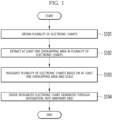
- FIG. 1 is a flowchart illustrating an example of a method by which a processor generates an integrated electronic chart, according to an embodiment.
- the processor 14 obtains a plurality of electronic charts.
- the plurality of electronic charts are charts that may provide navigation information and may be charts that include information about objects.
- the processor 14 extracts at least one overlapping area in the plurality of electronic charts.
- the processor 14 integrates the plurality of electronic charts based on the at least one overlapping area and a scale.
- the processor 14 may integrate the electronic chart with the largest scale among the plurality of electronic charts having the overlapping areas, as the overlapping area of the integrated electronic chart.
- the overlapping area may be determined based on the coordinate values (e.g., position values for a latitude or longitude) of each of the plurality of electronic charts, or the coordinate values of a coverage area.
- the processor 14 divides an integrated electronic chart generated through a plurality of integrations, into an arbitrary grid.
- the arbitrary grid may be a uniform or non-uniform grid, and further, a method of generating the grid cell, the shape and size of grid cells constituting the grid, and information included in the grid cell may be freely selected.
- the processor 14 may divide, into a grid, the integrated electronic chart generated by an integration, by using a quadtree depending on the presence or absence of an object. In more detail, based on a comparison between the size of the divided grid and a preset minimum grid size, the processor 14 redivides the divided grid by using a quadtree according to the presence or absence of an object included in the divided grid or the presence or absence of an object interpolated based on a division result.
- a quadtree division method may be used as a method for overcoming the non-uniform distribution of an electronic chart.
- the processor 14 may divide an integrated electronic chart into a grid such that an area containing object information in the integrated electronic chart becomes a quadtree, and repeatedly divide the grid of the integrated electronic chart by using a quadtree until a resulting grid contains preset object information. For example, in operation S103, the processor 14 may repeatedly perform redivision up to a preset minimum grid size. When a grid to be redivided is smaller than or equal to the minimum grid size, the processor 14 may no longer perform redivision.
- the processor 14 may repeatedly perform redivision according to the presence or absence of an object included in the redivided grid or the presence or absence of an object interpolated based on a redivision result.
- the processor 14 may redivide the redivided grid up to the preset minimum grid size.
- the preset minimum grid size may vary depending on the type of an object included in the redivided grid.
- the type of an object may be land, island, fish farm, anchoring area, or the like, and the minimum grid sizes of land, island, fish farm, and anchoring area may be set to be equal to or different from each other.
- the preset minimum grid size may be input by a user, or may be arbitrarily determined the processor 14.
- the processor 14 may perform object interpolation based on a plurality of points regarding objects included in the integrated electronic chart, and edges connecting the plurality of points to each other. Objects included in the integrated electronic chart may be indicated as a plurality of points.
- the processor 14 may connect the plurality of points to each other to generate one or more edges.
- the processor 14 may select a grid that does not include a point but includes an edge generated by connecting a plurality of points, and may generate additional object information in the selected grid. A method of performing object interpolation by using a plurality of points and edges will be described below with reference to FIG. 8 .
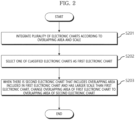
- FIG. 2 is a flowchart for describing an example of a method by which a processor integrates a plurality of electronic charts according to an overlapping area and a scale, according to an embodiment.
- operations S201 to S203 of FIG. 2 may be a detailed example of operations S101 to S103 of FIG. 1 .
- operation S104 of FIG. 1 may be performed.
- the processor 14 may integrate a plurality of electronic charts according to an overlapping area and a scale.
- the plurality of electronic charts used to generate an integrated electronic chart may include overlapping areas.
- the overlapping areas may vary for each of the plurality of electronic charts. example, while a first electronic chart and a second electronic chart may have area A as an overlapping area, the second electronic chart and a third electronic chart may have area B as an overlapping area.
- the processor 14 may classify the plurality of electronic charts based on the overlapping areas, to select an electronic chart to be included in an overlapping area of the integrated electronic chart.
- the processor 14 selects one of the classified electronic charts as a first electronic chart.
- the processor 14 may arbitrarily select one of the classified electronic charts as the first electronic chart.
- the processor 14 may select an electronic chart having the largest scale from among the classified electronic charts, as the first electronic chart.
- the processor 14 may omit operation S203, which will be described below, and include the selected first electronic chart in the integrated electronic chart.
- the processor 14 may change the overlapping area of the first electronic chart to the overlapping area of the second electronic chart.
- the processor 14 may select an electronic chart with the largest scale as an electronic chart to be included in the integrated electronic chart.
- the processor 14 may classify a plurality of electronic charts having different scale levels based on overlapping areas, and extract the types and coordinates of objects within the overlapping areas from the classified electronic charts.
- the processor 14 may select one of the classified electronic charts as the first electronic chart.
- the processor 14 may change the overlapping area of the first electronic chart to the overlapping area of the second electronic chart.
- the processor 14 may extract the types and coordinates of objects in the overlapping areas from the classified electronic charts, and when an electronic chart containing the same object type and coordinates as a current electronic chart and having a larger scale than the current electronic chart is selected as a next electronic chart, change the overlapping area of the current electronic chart to the overlapping area of the next electronic chart.
- different minimum node sizes may be applied to the respective extracted objects by using the types and coordinates of the objects, and a division operation may be performed by using a quadtree. Because each object has a different degree or direction of influence on driving of a ship, division is performed by using the types of objects considered when generating an integrated electronic chart.
- the processor 14 may perform electronic chart extraction according to scale by considering only the overlapping areas based on overlapping of areas within a map, but may also additionally consider objects included in the overlapping areas.
- the processor 14 may extract the electronic chart that contains the object to construct an integrated electronic chart.
- the object may be filtered to remove information in the electronic chart, which is unnecessary for driving of the ship. This is to prevent memory from being wasted as an object that is meaningless in setting of a route of the ship is included in the integrated electronic chart.
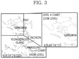
- two electronic charts KR3F2K00 and KR4F2K10 for a Ganghwa area may be stored in an electronic chart database (DB) 130.
- the first two letters in the electronic chart number are a code of the country of production of the electronic chart, and the third letter is a code for each navigation purpose, also referred to as a level number, and refers to the scale level of the chart.
- the remaining letters of the electronic chart may be a cell code determined by the country.
- KR3F2K00 is an electronic chart with a scale level of 3
- KR4F2K10 is an electronic chart with a scale level of 4
- KR3F2K00 may be a high-level electronic chart
- KR4F2K10 may be a low-level electronic chart.
- KR4F2K10 expresses the Ganghwa area in more detail by enlarging it at the lower level, and thus may contain more detailed information about an overlapping area, that is, the Ganghwa area, than KR3F2K00.
- an integrated electronic chart containing more detailed information may be obtained by generating an integrated electronic chart by using the electronic chart with a scale level of 4 for the Ganghwa area, which is the overlapping area.
- electronic charts KR4G1N40, KR5G1N43, and KR669D82 has various types depending on their purposes and areas, may contain various pieces of data such as water depth, tide, or navigational hazard, and may have different scales.
- An area marked with a dotted line corresponds to an overlapping area between the level-4 electronic chart KR4G1N40, the level-5 electronic chart KR5G1N43, and the level-6 electronic chart KR669D82.
- the processor 14 may use only the area belonging to the level-6 electronic chart KR669D82 with the largest scale, without using the level-4 electronic chart KR4G1N40 and the level-5 electronic chart KR5G1N43. In other words, the processor 14 may generate an integrated electronic chart based on data of the electronic chart with the largest scale for an overlapping area between a plurality of electronic charts.
- the processor 14 may classify a plurality of electronic charts with different scales based on overlapping areas, then perform preprocessing to replace an overlapping area according to a scale level, combine each area of the plurality of electronic charts, and generate an integrated electronic chart.
- the processor 14 may generate an integrated electronic chart with a high resolution by combining electronic charts with the largest scale for an overlapping area among the plurality of electronic charts.
- the processor 14 may generate an integrated electronic chart containing all information related to driving of the ship by integrating electronic charts containing different objects for respective purposes.
- the electronic charts have different scales, and the processor 14 may perform integration according to the scale level of each electronic chart.
- the scale level may include a scale value and a scale comparison with another electronic chart.
- an integrated electronic chart may be generated by combining electronic charts with large scales with respect to an overlapping area between a plurality of electronic charts with different scales.
- An integrated electronic chart may be generated by preprocessing the scales of a plurality of electronic charts with different scales to be equal to each other, and then combining the electronic charts with each other.
- an integrated electronic chart with a high resolution may be generated by extract an electronic chart with the largest scale from electronic charts containing one area among a plurality of electronic charts with different scales, extracting an electronic chart with the largest scale from electronic charts that include another area, and combining the electronic charts with the largest scale for the entire area.
- the processor 14 may, when electronic chart integration for all overlapping areas is completed, store the integrated electronic chart, and when electronic chart integration for all overlapping areas is not completed, perform operation S201 to S203 described above again for the next overlapping area.
- FIG. 5 is a flowchart for describing another example of a method by which a processor integrates a plurality of electronic charts according to an overlapping area and a scale, according to an embodiment.
- the processor 14 In operation S601, the processor 14 generates a list in which electronic charts are classified according to an overlapping area, for a plurality of electronic charts with different scales.
- the processor 14 may classify electronic charts by considering one or more of chart numbers, chart names, scales, and code numbers of the electronic charts, and generate a list by sequentially sorting the classified electronic charts.
- the chart number of the electronic chart contains electronic chart information, and thus, the processor 14 may perform classification by using the chart number.
- the processor 14 sets a first area as a current area in the electronic chart list classified according to the overlapping area.
- the first area is a particular area included in the plurality of electronic charts, and the plurality of electronic charts may consist of the first area, a second area, ... , and an n-th area.
- This is to configure combined_chart by extracting electronic charts including an overlapping area according to the scale levels of the electronic charts included in the classified electronic chart list, and to determine whether to extract by determining the scale level of the current electronic chart.
- the processor 14 may determine whether the current electronic chart has the largest scale for the first area, which is the current area. When the current electronic chart has with the largest scale (YES in S604), in operation S607, the processor 14 may add the current electronic chart to combined_chart as it is, and store combined_chart as an integrated electronic chart of the current area. In other words, combined_chart may be the current electronic chart.
- the processor 14 may remove all areas of an electronic chart with a larger scale from the current electronic chart, and add the remaining areas to combined_chart.
- an area also included in an electronic chart with a larger scale is removed from the current electronic chart such that the area may be extracted from the electronic chart with a larger scale and used, and only the nonoverlapping areas are used to configure the integrated electronic chart.
- the processor 14 may change current chart to an electronic chart with a next scale for the current area. In addition, the processor 14 may repeat electronic chart extraction until the current electronic chart has the largest scale.
- the processor 14 may determine whether integration of electronic charts for all areas has been completed. When the electronic charts for all areas have been integrated (YES in S608), the processor 14 may terminate the electronic chart integration process. In other words, the processor 14 may set area n as the current area, and when storage of the integrated electronic chart is completed, determine that generation of the integrated electronic chart has been completed, and terminate the process.
- the processor 14 may set the m-th area, which is the next area, as the current area, and repeat operations S603 to S608.
- an integrated electronic chart may be generated by integrating electronic charts containing the most detailed information for all areas included in the plurality of electronic charts.
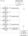
- FIGS. 6A and 6B are flowcharts for describing an example of a process in which a processor integrates electronic charts by using a quadtree for each object, according to an embodiment.
- FIGS. 6A and 6B will be collectively referred to as FIG. 6 .
- FIG. 6 summarizes an algorithm for generating a final quadtree-based integrated electronic chart for all objects by integrating quadtree-based integrated electronic charts for each object, and it is assumed that x is a unique number (n) assigned to an arbitrary grid, combined world is a final quadtree-based integrated electronic chart, base world is an electronic chart previously integrated into combined world, and world is an electronic chart to be merged into combined world.
- base world and world are results of division using a quadtree according to selected objects, and may be integrated electronic charts based on a quadtree for each object.
- world[x] denotes a grid with x as a unique number (n) in world
- combined world[x] denotes a grid with x as a unique number (n) in combined world
- base world[x] denotes a grid with x as a unique number (n) in base world. Grids having the same size in the same area have the same unique number (n) in base world and world.
- base world and world are quadtree-based integrated electronic charts for each object divided by using quadtrees according to each selected object, and may have different minimum node sizes when objects are different from each other.
- base world is divided into grids having a parent grid size and world is divided into grids having a child grid size, for the same area on the electronic chart, world[x] that exists in world may not exist in base world. In other words, there may be no base world[x].
- the grid with the unique number x (base world[x]) is not in base world (x in base world? - "False"), it means that the grid sizes are different because the number of divisions of base world is different in an electronic chart area corresponding to grid x of world (world[x]). That is, the grid of base world has the size of the parent grid, and the grid of world has the size of the child grid.
- x having the size of the child grid is denoted as "x”
- the grid having the size of the parent grid of the child grid is denoted as "parent x”.
- base world[x] is a grid that may be passed through and has no or few objects that will affect a movement of the ship
- world[x] is a parent grid that necessarily contains object information that will affect the movement of the ship
- world[x] replaces the electronic chart of the corresponding area.
- base world[x] is a grid that cannot be passed through, even though the area in another integrated electronic chart for each object may be passed through, it cannot be passed through due to object information of base world[x], thus, there is no need to update the electronic chart of the area, and thus the electronic chart of the base world[x] is maintained without replacement.
- base world[x] When the grid with the unique number x (base world[x]) is in base world ("x in base world?" - "True"), it means that the grid sizes are equal to each other because the number of divisions of base world is the same in an electronic chart area corresponding to grid x of world (world[x]).
- world[x] when world[x] is a grid through which the host ship may pass, base world[x] may be a grid having the same size as world[x] through which the host ship cannot pass, may be a grid having the same size as world[x] through which the host ship may pass, or may be maintained as base world[x].
- the processor 14 may generate an integrated electronic chart by integrating a plurality of electronic charts.
- examples of integrating a plurality of electronic charts are not limited to the above.
- FIG. 7 is a diagram for describing an example of a method by which a processor divides an integrated electronic chart into a grid by using a quadtree, according to an embodiment.
- FIG. 7 may be a diagram for describing operation S102 of FIG. 1 .
- a quadtree-based electronic chart is an electronic chart divided by using a quadtree.
- a quadtree is a tree structure having only four child nodes, and a grid of an area with many objects may be further subdivided, and a grid of an area with few objects may be coarsely divided to form a non-uniform grid.
- the number of divisions may be variously adjusted for each of grids included in an integrated electronic chart depending on object information, and even when the same resolution and memory are allocated to each grid, the resolution and memory may be concentrated in areas with many objects, enabling efficient use of computing resources.
- grids 50, 60, 70, and 80 having a first size exist, and the grids 50 and 70 are not divided.
- the preset minimum grid size may vary depending on the type of an object included in the grid.
- object information is contained in the grid 50, but when the minimum grid size according to the type of an object is greater than or equal to the size of the grid 50, further division may not be performed.
- the grid 70 does not contain object information, and thus may not be further divided.
- redivision may be performed depending on the presence or absence of object information therein.
- the third grid of the grid 80 contains object information, the third grid may be divided by using a quadtree to form child grids again.
- a child grid 8031 of the child grid may be formed.
- FIG. 8 is a diagram for describing another example of a method by which a processor divides an integrated electronic chart into a grid by using a quadtree, according to an embodiment.
- FIG. 8 may be a diagram for describing operation S103 of FIG. 1 .
- the processor 14 may express an object as one point 1001 or one edge 1002 and perform grid division by determining a maximum number of divisions.
- the processor 14 may express an object as one point 1001 in a generated integrated electronic chart, and connect the points 1001 to generate the edge 1002 (1010).
- the integrated electronic chart may be data including the points 1001, and the processor 14 may arbitrarily generate the edge 1002 by connecting the points 1001.
- the processor 14 may divide the grid into a grid by using a quadtree depending on the presence or absence of a point 1001 or an edge 1002 (1020).
- the processor 14 may perform division on a grid containing the point 1001 or the edge 1002 up to the minimum grid size, and stop further division on a grid that does not contain the point 1001 or the edge 1002 (1030). As a result, the processor 14 may generate a primary quadtree-based integrated electronic chart.
- the processor 14 fills the grid containing the point 1001 representing an object in the primary quadtree-based integrated electronic chart, with a black block (1040).
- the processor 14 may perform interpolation between the points 1001 to form a new object 1003 in an area through which the edge 1002 passes, among grids not filled with the black blocks (1050). For example, when an edge generated by connecting the points 1001 passes through a grid that is not filled with the black block, the processor 14 may perform interpolation to form a new object 1003 in the corresponding grid.
- the processor 14 may redivide the primarily divided grid by using a quadtree according to the presence or absence of the new object 1003 in the divided grid (1060). As a result, the processor 14 may generate a secondary quadtree-based integrated electronic chart.
- the processor 14 may fill the grid containing the new object 1003 other than the point 1001 representing the object in the secondary quadtree-based integrated electronic chart with a black block (1070).
- the processor 14 may fill the closed area with a black block (1080).
- a route setting unit may determine that the area filled with the black block is a route on which the ship cannot travel due to the presence of the object, and thus set a route with other areas than the area filled with the black block.
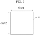
- the processor 14 may compare the size of a divided grid with a preset minimum grid size. For example, the processor 14 compares the smaller of a length dist1 connecting the upper left point to the upper right point of the divided grid and a length dist2 connecting the upper left to the lower left point of the divided grid, with the preset minimum grid size.
- the length dist1 connecting the upper left point to the upper right point of the divided grid or the length dist2 connecting the upper left point to the lower left point of the divided grid may be calculated by using the Haversine formula.
- the processor 14 may store attribute information of a grid included in an integrated electronic chart by using information about the grid of the integrated electronic chart and information about an object contained in the grid of the integrated electronic chart.
- attribute information of a grid stored by the processor 14 will be described with reference to FIG. 10 .
- FIG. 10 is a diagram for describing an example of attribute information of a grid included in an integrated electronic chart, according to an embodiment.
- a parent grid 50 may contain a unique number (n) assigned to the grid, attribute (info) information, and unique numbers of child grids (children) included in the parent grid 50.
- n unique number assigned to the grid
- info attribute
- children unique numbers of child grids (children) included in the parent grid 50.
- the coordinates of the lower left corner, width, and height of each grid, a route weight (cost) depending on the type of an object included in the grid, and the number of divisions (depth) may also be included.
- the numbers of divisions (depth) of the parent grid 50 are d+1, and thus, the depth increases by 1 for one division.
- the child nodes 1, 2, 3, and 4 form 16 grandchild nodes 5 to 20 by using a quadtree, the depth of the child node is 2.
- the depth cannot exceed the maximum number of divisions (MAX_depth) of a node, and the minimum grid size may be determined according to the maximum number of divisions.
- the child nodes, the grandchild nodes, and the great-grandchild nodes are all expressed as child grids 501, 502, 503, and 504, and a grid including the child grids 501, 502, 503, and 504 is defined as the parent grid 50.
- Attribute information has one of 0, 1, and 2, where 2 may represent a grid with child grids, 1 may represent a grid without objects among the child grids such that the host ship may pass therethrough, and 0 0 may represent a grid among the child grids in which an object is located such that the host ship cannot pass therethrough.
- a grid without child grids has an attribute of 1
- the grid is a grid through which the host ship may pass
- a grid without child grids has an attribute of 0, the grid is blocked such that host ships cannot pass therethrough.
- the attribute information (info) may include information about a grid of an integrated electronic chart and information about an object included in a grid of the integrated electronic chart.
- Information about a grid of an integrated electronic chart may include position information of the grid, size information of the grid, a route setting weight, and the like, as physical information of the grid.
- Information about an object included in a grid of an integrated electronic chart may include information about the type of the object, the size of the object, the position of the object, and the like.
- the processor 14 may store, for a divided grid, an attribute of the grid, and may further store the size and identification number of each grid, the type of an object included in the grid, a minimum grid size and a route setting weight according to the type of an object, and the coordinates of a corner edge.
- the processor 14 may calculate a collision probability of the host ship by using attribute information (info), and set a route according to the calculated collision probability. For example, by setting a route setting weight for a grid adjacent to a land, a route may be set to avoid the grid adjacent to the land.
- info attribute information
- FIG. 11 illustrates an integrated electronic chart divided into arbitrary grids.
- a sea area 91 through which a ship may pass and a land area 92 may be distinguished and displayed.
- the processor 14 may distinguish and display, among grids determined as passable areas, a sea area 922 of which the distance to a land is less than or equal to a preset distance, and a sea area 921 of which the distance to a land is greater than or equal to the preset distance.
- the processor 14 may set the weight of the sea area 921 to be less than the weight of the sea area 922, such that the sea area 921 more affects route setting.
- the integrated electronic chart divided into arbitrary grids in the embodiment of FIG. 11 may be an integrated electronic chart divided by using a quadtree.
- a grid of which the distance to a land is less than or equal to the preset distance may be set with a high route setting weight, and thus may be avoided when setting a route.
- the preset distance may be set in consideration of the total width of an area through which a ship may pass (e.g., sea or river). For example, when the total width of the area through which a ship can pass is narrower than when the total width of the area through which a ship can pass is wide, the preset distance may be set to be small.
- a movement in an area with a high weight is avoided, and thus, it is possible to plan a safe route that is a certain distance away from a land.
- a route is set only with route setting weights without calculating the actual distance from a land, a gain in calculation time may be achieved.
- FIG. 12 is a diagram for describing an example of an integrated electronic chart generated by a processor using an integrated electronic chart generation method, according to an embodiment.
- FIG. 13 is a diagram for describing another example of an integrated electronic chart generated by a processor using an integrated electronic chart generation method, according to an embodiment.
- the electronic chart may be monitored by using attribute information of the grid.
- the processor 14 may express, in black, a grid on which a ship cannot travel, such as a land area, based on attribute information (e.g., 0) of the grid, or may monitor the electronic chart focusing on areas with a large number of grids by non-uniformly distributing grids according to object information contained in the grids.
- a quadtree-based integrated electronic chart may be displayed in different colors or patterns based on attribute information.
- an area on which a ship cannot travel because the area has an attribute of 0 or is surrounded by an area with an attribute of 0 may be displayed in black, and may correspond to, for example, a land node.
- an area displayed in black may correspond to the black block described above with reference to FIG. 8 .
- a submarine area near a land area may be displayed in blue, and an area of which the water depth becomes low due to a tidal difference may be displayed in gray.
- An area with no object but having a maritime environment that may affect the ship may be displayed with a separate color or mark.
- an area with an attribute of 1 but with an object such as an obstacle may be displayed in red.
- an area with no object such as an obstacle may be displayed in white.
- each area may be shown in detail such that the user may conveniently perform monitoring and set a ship travel route.
- the colors described above are only exemplary embodiments, and each area may be separately depicted by using other distinguishing colors or marks.
- the position of the object may be displayed accurately without significantly changing the overall chart capacity.
- a minimum grid size for each object may variously adjusted according to terrain information such as a land terrain, a submarine terrain, an obstacle terrain, or a marine parking area, and by applying different grid sizes to respective objects to generate a quadtree-based integrated electronic chart, a position may be displayed accurately without significantly changing the storage capacity of the integrated electronic chart.
- a route may be set by using an integrated electronic chart generated by using the above-described quadtree.
- a route setting method may include setting a route from the starting point to the destination by connecting grids other than grids containing objects or a grid surrounded and closed by the grids containing the objects.
- the processor 14 may calculate a collision risk of a host ship based on an integrated electronic chart to which object information (e.g., information about another ship) detected from a sensor is mapped.
- object information e.g., information about another ship
- second object information e.g., another ship, a target, or a person
- the processor 14 may reset the route to include a grid with a low collision risk by considering a collision risk calculated for the current route and a possibility of avoidance of the host ship.
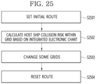
- the processor 14 may set an initial route based on a quadtree-based integrated electronic chart, and set the initial route by connecting grids that do not contain the first object information or grids with a low collision risk among the grids.
- the processor 14 may calculate a host ship collision risk for each grid by mapping the second object information to the integrated electronic chart in real time, and calculate a collision risk of the corresponding grid by considering the first object information included in each grid, the second object information mapped to the corresponding grid, the possibility of collision when the host ship travels along the initial route, the possibility of bypass of another ship when the second object is the other ship, and the like.
- the processor 14 may determine whether a second object is located on the initial route, by using host ship information including the position, speed, direction, and pose of the host ship, and when the second object is located, calculate a collision risk to be inversely proportional to the distance between the host ship and the second object.
- a collision risk may be calculated by considering an initial route passage time of the other ship and the distance between the host ship and the second object.
- some grids may be changed according to the calculated collision risk, and the route may be reset accordingly.
- the calculated collision risk is greater than a reference value
- a grid through which the initial route passes may be changed to another grid.
- the processor 14 may reset a bypass route within the same grid instead of changing the grid.
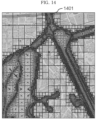
- FIG. 14 shows a graph generated by dividing an integrated electronic chart 1401 by using an arbitrary grid and connecting divided grids.
- the arbitrary grid may be divided by using a quadtree.
- the graph may be a line segment connecting adjacent grids among grids on which a ship may move.
- the center points of the grids may be connected to each other or the vertices of the grids may be connected to each other, but the present disclosure is not limited thereto.
- the connected graph may be used when setting a route.
- the processing efficiency may be improved by reducing the size of data occupied by the integrated electronic chart and shortening the access time to attribute information of each coordinate.
- FIG. 15 is a block diagram briefly illustrating a configuration of an integrated electronic chart generation device and an shipboard user device, according to an embodiment.
- an integrated electronic chart generation unit 100 may include an electronic chart integration unit 110 and a quadtree division unit 120 that perform tasks by using the above-described instructions.
- the electronic chart integration unit 110 may receive a plurality of electronic charts with different scales stored in the electronic chart DB 130, and integrate them according to a scale based on an overlapping area.
- the quadtree division unit 120 may generate a grid-based integrated electronic chart by dividing the integrated electronic chart by using a quadtree according to the presence or absence of an object.
- the integrated electronic chart generated by the integrated electronic chart generation unit 100 may be divided according to each area, and may be stored in an electronic chart storage unit 210 of an shipboard device 200 as a divided electronic chart.
- the integrated electronic chart may be used in small capacity units by using the divided electronic chart, and thus may be viewed not only on a shipboard computing device but also on a portable device such as a mobile device.
- the area determination unit 220 may extract a divided integrated electronic chart containing an area corresponding to the current position and display it on a display unit 230.
- GPS global positioning system
- the integrated electronic chart generation unit 100 may include instructions for performing operations S101 to S103 of FIG. 1 , and according to execution of each operation, the operation may be logically distributed to the electronic chart integration unit 110 and the quadtree division unit 120. This is distribution according to function and may actually be implemented by integrating into one computing device, or may be implemented separately in each physically independent computing device.
- FIG. 16 is a block diagram for describing an example of a computing environment including a computing device, according to an embodiment of the present disclosure.
- respective components may have different functions and capabilities in addition to those described below, and additional components other than those described below may be included.
- a computing environment 10 illustrated in FIG. 16 may include a computing device 12, and the computing device 12 may include a computer-readable storage medium having recorded there on a computer program to be executed on a computer to perform the above-described method of generating an integrated electronic chart or method of generating an electronic chart by dividing a generated integrated electronic chart based on an arbitrary grid.
- the computing device 12 may include a computer-readable storage medium having recorded thereon a computer program to be executed such that a route setting method using an integrated electronic chart or an electronic chart divided into an arbitrary grid, which will be described below, is performed on a computer.
- the computing device 12 includes at least one processor 14, a computer-readable storage medium 16, and a communication bus 18.
- the processor 14 may cause the computing device 12 to operate according to the example embodiments described above.
- the processor 14 may execute one or more programs stored in the computer-readable storage medium 16.
- the one or more programs may include one or more computer-executable instructions, which, when executed by the processor 14, cause the computing device 12 to perform operations according to the example embodiments.
- the computer-readable storage medium 16 is configured to store computer-executable instructions or program code, program data, and/or other suitable form of information.
- a program 20 stored in the computer-readable storage medium 16 includes a set of instructions executable by the processor 14.
- the computer-readable storage medium 16 may be a memory (a volatile memory such as random-access memory, a non-volatile memory, or an appropriate combination thereof), one or more magnetic disk storage devices, optical disk storage devices, flash memory devices, other storage media that are accessible by the computing device 12 and capable of storing desired information, or a suitable combination thereof.
- the communication bus 18 connects various other components of the computing device 12, including the processor 14 and the computer-readable storage medium 16, to each other.
- the computing device 12 may also include one or more input/output interfaces 22 configured to provide an interface for one or more input/output devices 24, and one or more network communication interfaces 26.
- the input/output interface 22 and the network communication interface 26 are connected to the communication bus 18.
- the input/output device 24 may be connected to other components of the computing device 12 through the input/output interface 22.
- the exemplary input/output device 24 may include, but is not limited to, input devices such as a pointing device (e.g., a mouse or a trackpad), a keyboard, a touch input device (e.g., a touchpad or a touch screen), a voice or sound input device, various types of sensor devices and/or photographing devices, and/or output devices such as a display device, a printer, a speaker, and/or a network card.
- the exemplary input/output device 24 may be included in the computing device 12 as a component constituting the computing device 12, or may be connected to the computing device 12 as a separate device from the computing device 12.
- an integrated electronic chart generation device is a computing device including a processor and a memory storing a computer program to be executed on a computer by the processor, wherein the computer program may include instructions for integrating a plurality of electronic charts according to an overlapping area and a scale, dividing the integrated electronic chart generated by integration into a grid by using a quad tree according to the presence or absence of an object, and redividing the divided grid by using a quadtree according to the presence or absence of an objects included in the divided grid or the presence or absence of an object interpolated based on a division result, based on a comparison between the size of the divided grid and a preset minimum grid size.
- FIG. 17 is a block diagram for describing a route setting device using an electronic chart, according to an embodiment of the present disclosure.
- a route setting device 1000 using an electronic chart may include an electronic chart storage unit 1300 configured to store at least one of a plurality of electronic charts, an integrated electronic chart, and an electronic chart (or integrated electronic chart) divided by an arbitrary grid, a sensor unit 1100 including a plurality of sensors (e.g., a light-detection-and-ranging (LiDAR) 1120 or a camera 1110) configured to sense the surroundings of a host ship, a sensor fusion and mapping unit 1400 configured to generate integrated object information by fusing various types of obtained object information with the integrated electronic chart, and map the integrated object information to a grid of the integrated electronic chart in real time, and a route setting unit 1500 configured to set a route from a starting point to a destination by connecting grids to which the object information is not mapped or grids with a low collision risk in the integrated electronic chart.
- the route setting device 1000 may further include a display unit 1600 configured to display the integrated object information, a
- the sensor unit 1100 includes a sensor configured to sense the surroundings of the host ship.
- the sensor unit 1100 may include a sensor installed primarily on large ships, such as a radar 1130 or an automatic identification system (AIS) 1140.
- the sensor unit 1100 may include a front camera included in a small ship, a surround view monitor (SVM) camera, a LiDAR, a radar, an AIS, a sonar, and the like.
- the front camera may sense the type of an obstacle, pixel coordinates in an image domain, and the approximate position of an obstacle within 300 m.
- the SVM camera may sense the distance to the nearest obstacle.
- the LiDAR may sense the exact position of an obstacle at a distance of 10 to 200 m, and provide indicators for collision risk assessment such as Speed Over Ground (SOG), Course Over Ground (COG), Closest Point of Approach (CPA), or Time to Closest Point at Approach (TCPA).
- the radar may sense the position of an obstacle at a distance of 200 m to 8 km, and provide indicators for collision risk assessment such as SOG, COG, CPA, or TCPA.
- the AIS may sense the position of an obstacle over several kilometers and the direction of the bow, and may provide indicators for collision risk assessment such as SOG, COG, CPA, or TCPA.
- the sonar may sense a depth below a water surface with precision in real time.
- the electronic chart storage unit 1300 may store a plurality of electronic charts with different scales and/or an integrated electronic chart obtained by performing preprocessing and integration according to a scale level based on an overlapping area of the plurality of electronic charts.
- the electronic chart storage unit 1300 according to an embodiment of the present disclosure may store an integrated electronic chart divided into an arbitrary grid, or a quadtree-based integrated electronic chart.
- the electronic chart storage unit 1300 may store a plurality of electronic charts with various scale levels according to different purposes and areas, and when storing an electronic chart in which a plurality of electronic charts with different scales are integrated, may generate the integrated electronic chart by combining electronic charts that may obtain the highest resolution image with respect to an overlapping area with the largest scale among the plurality of electronic charts.
- the sensor fusion and mapping unit 1400 may be configured to integrate object information and remove duplicate second object information.
- the processor 14 may obtain first object information contained in an integrated electronic chart, and second object information detected from a sensor.
- the first object information and the second object information may be redundantly generated for the same object.
- a plurality of sensors may redundantly sense the same object, thereby generating a plurality of pieces of second object information.
- the sensor fusion and mapping unit 1400 may integrate the object information.
- the sensor fusion and mapping unit 1400 may integrate second object information detected from data from the LiDAR 1120, and second object information detected from an image from the camera 1110 existing within a preset range.
- the sensor fusion and mapping unit 1400 may be configured to remove second object information detected in a preset area of the integrated electronic chart, for example, second object information detected in a land area of the integrated electronic chart.
- the route setting unit 1500 may be configured to calculate a probability-based collision risk of the host ship based on an integrated electronic chart to which object information is mapped, and when object information occurs in a grid to which object information is not mapped, change some grids by considering a collision risk calculated for a current route and the possibility of avoidance of the host ship, and reset the route.
- an 'integrated electronic chart' for setting a route may be understood as a concept that includes both an integrated electronic chart generated according to an embodiment of the present disclosure or an electronic chart obtained by dividing a generated integrated electronic chart based on a quadtree.
- the above-described configuration may be performed within one computing device in logically divided units according to function, or may be implemented in independent units according to respective functions.
- the above-described configuration may be performed by processor 14 of FIG. 16 .
- the route setting device 1000 described above may perform a route setting method using a quadtree-based electronic chart according to an embodiment of the present disclosure.
- a route setting method using a quadtree-based electronic chart may perform a route setting method using a quadtree-based electronic chart according to an embodiment of the present disclosure.
- an example of a method of setting a route using a quadtree-based electronic chart will be described with reference to FIG. 18 .
- FIG. 18 is a flowchart for describing an example of a method by which a processor sets a route by using an integrated electronic chart, according to an embodiment.
- operations S1801 to S1804 are described as being performed by the processor 14, but are not limited thereto and may also be performed by the sensor fusion and mapping unit 1400, the route setting unit 1500, and the display unit 1600 of FIG. 17 .
- the processor 14 receives an electronic chart containing first object information.
- the processor 14 may receive a quadtree-based integrated electronic chart generated by a server.
- the first object information refers to information about objects included in the integrated electronic chart.
- the first object information may include information about a land, a port, a fixed obstacle, a fish farm, or an anchoring area.
- Integrated electronic charts are of various types depending on their purpose, contain a variety of data such as a water depth, tides, or a navigational hazard, and may have different levels, that is, different scales.
- the processor 14 receives data including second object information from at least one sensor.
- the second object information refers to information about an object detected based on sensor data obtained from a sensor.
- the second object information may include another ship, a target, or a person.
- the second object information may be distinguished from the first object information that may be obtained from the integrated electronic chart.
- the processor 14 may obtain the second object information by using various sensors such as the radar 1130, the AIS 1140, a front camera, an SVM camera, a LiDAR, or a sonar.
- operation S1802 is described as being performed after operation S1801, operation S1801 and operation S1802 may be performed simultaneously.
- first object information and second object information may be managed as a common data structure.
- Recognition sensor Decimal value Front camera True 2 0 * 1 SVM camera False 2 1 * 0 LiDAR True 2 2 * 1 RADAR True 2 3 * 1 AIS False 2 4 * 0 SONAR True 2 5 * 1 Electronic chart False 2 6 * 0 Result value 45
- the processor 14 may derive a sum of decimal values for the presence or absence (True or False) of a plurality of sensors and an electronic chart, as a result value. In other words, the processor 14 may determine which sensors exist only with the result value. According to an embodiment of the present disclosure, the processor 14 manages the obtained object information as a common data structure such that it may be commonly used. When fog, a wave, or the like that is not a physical object that interferes with actual driving, is detected as an object by the AIS 1140, the LiDAR 1120, or the camera 1110 due to environmental factors, the processor 14 may filter out it by using a noise removal algorithm.
- the processor 14 may detect an object located around the small ship, perform object filtering by using land information of the integrated electronic chart and a noise removal algorithm, and then perform recognition to identify the type of the filtered object.
- the processor 14 may select only objects corresponding to driving obstacles by performing sensor fusion on the first object information of the integrated electronic chart and the second object information that is filtered by using a noise removal algorithm.
- the processor 14 may generate integrated object information based on the first object information and the second object information, and map the integrated object information to a grid of the integrated electronic chart. Meanwhile, the processor 14 may integrate object information detected in data from the LiDAR 1120 and object information detected in an image from the camera 1110 existing within a preset range.
- the processor 14 may filter the second object information detected in a land area of the integrated electronic chart.
- the processor 14 may filter the second object information by using a noise removal algorithm, and integrate the filtered object information to generate integrated object information.
- the processor 14 may filter the second object information by using a noise removal algorithm, and integrate object information for the filtered object. Because land information is electronic chart information irrelevant to driving of a ship, the memory capacity may be saved by filtering or deleting the second object information detected in the grid containing the first object information of the integrated electronic chart.
- Information obtained from the sensor unit 1100 may redundantly detect the same object, and thus, when sensor data is used without processing the information, errors may occur in route setting or the like. According to an embodiment of the present disclosure, the above-described problem may be solved by generating integrated object information about the same object by using the first object information and the second object information.
- the processor 14 may use the first object information and the second object information to generate integrated object information about the same object by considering the position of the object, the size of the object, the speed of the object, the moving direction of the object, and the like.
- the integrated object information generated in operation S1803 may be mapped to mapping data divided into an arbitrary grid.
- particular mapping data divided into an arbitrary grid may be an electronic chart (or an integrated electronic chart according to an embodiment of the present disclosure), data sensed from a plurality of sensors 2201 (an image-based object recognition result obtained by the camera 111), or the like.
- a method of generating the grid, the shape (which may be uniform or non-uniform) and size of grid cells constituting the grid, and information contained in the grid cells may be freely selected.
- the electronic chart may be an electronic chart containing the first object information mentioned in S1801 divided into an arbitrary grid, but may also be a separate electronic chart divided into an arbitrary grid.
- the processor 14 displays the integrated object information.
- the processor 14 may display the integrated object information based on mapping data that is mapped to the integrated object information and divided into an arbitrary grid.
- the processor 14 may display the integrated object information based on an electronic chart or monitoring image to which an integrated object is mapped.
- the monitoring image is a monitoring image generated based on data sensed from the sensors 2201, and may be a cluster image representing the surrounding environments of the host ship as a three-dimensional model.
- FIG. 19 is a diagram briefly illustrating objects around a host ship.
- FIG. 20 is a diagram for describing information obtained by a processor sensing the objects of FIG. 19 , according to an embodiment.
- external ships 42 or marine structures 43 may be located around a host ship 41, and there may be a person 44 who fell from the host ship 41.
- the host ship 41 performs a berthing or unberthing or moves close to a land, there may be the land or an obstacle 45 located on the land around the host ship 41.
- the camera 1110 may detect three objects C1, C2, and C3, the AIS 1140 may detect three objects A1, A2, and A3, the radar 1130 may detect three objects R1, R2, and R3, and the LiDAR 1120 may detect two objects L1 and L2.
- the processor 14 may detect only some obstacles as objects depending on the type of sensor and detect the same obstacle redundantly, and thus may receive 11 inputs as illustrated in FIG. 20 .
- the processor 14 may integrate detections of the same object and reserve detections of different objects.
- the processor 14 converts sensor data obtained from a plurality of sensors into the same format and performs the above-described sensor data processing, and thus may consistently process various pieces of sensor data obtained from the plurality of sensors when using them for calculating a collision risk or the like.
- the processor 14 generates integrated object information will be described with reference to FIG. 21 .
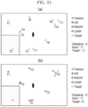
- FIG. 21 is a diagram for describing an example in which a processor generates integrated object information about the same object, according to an embodiment.
- the processor 14 may recognize T3 and T4, which are recognized by both the camera 1110 and the LiDAR 1140 and are located very close to each other on the chart, as one obstacle, and integrate then into 'T2' as illustrated in (b) of FIG. 21 .
- the processor 14 may recognize T9, T10, and T11, which are recognized by the AIS 1140 and the radar 1130, additionally recognized by the camera 1110, and are located close to each other on the chart, as one obstacle, and integrated them into 'T6' as illustrated in (b) of FIG. 21 .
- the processor 14 may recognize T5 and T7, which are recognized by both the AIS 1140 and the radar 1130 and are located close to each other on the chart, as one obstacle, and integrate then into 'T4' as illustrated in (b) of FIG. 21 .
- the processor 14 may regard them as one target object and fuse sensor data.
- the processor 14 may regard the sensor data as one target object and fuse the sensor data.
- the processor 14 may further integrate and organize the sensor data of the electronic chart, and in this case, when the radar 1130 detects the land or the obstacle 45 located on the land, the processor 14 may exclude the obstacle 45 from the target objects by using the sensor data of the electronic chart. Because the host ship 41 does not drive on land, computing resources may be saved by ignoring obstacles in the corresponding area by using land information of the electronic chart.
- T2 detected by the radar 1130 is an obstacle located on the land on the electronic chart, and objects located on land on the electronic chart may be removed or deleted without being used for sensor data fusion.
- recognition errors may be reduced not by simply listing sensor data, which is recognition results by a plurality of sensors, but by fusing them, such as integrating or deleting them, and displaying them on a single electronic chart.
- mapping object information fused with the electronic chart and plotting it as illustrated in (b) of FIG. 21 rather than simply arranging the object information fused with the electronic chart side by side on a screen, a user who is driving while keeping eyes forward may easily monitor results detected by the sensors, and there is no room to confuse the user with unnecessary information for driving, such as a land or the obstacle 45 located on a land.
- object information may include probability information regarding the existence of an object.
- the probability information may be expressed as a probability model and may calculated by using a Kalman filter.
- the integrated object information may include integrated probability information generated by integrating probability information of objects.
- the integrated electronic chart may be provided with the integrated probability information mapped to the grid of the integrated electronic chart.
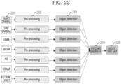
- the processor 14 may preprocess data obtained from the plurality of sensors 2201 (2202). For example, the processor 14 may receive sensed data from the plurality of sensors 2201, and parse and convert the sensed data for each sensor manufacturer.
- the processor 14 may generate object information by recognizing an object based on the parsed and converted data (2203).
- the generated object information may be managed as a common structure as described above.
- the processor 14 may fuse the object information to generate integrated object information (2204) and map the integrated object information to mapping data divided into an arbitrary grid (2205).
- the mapping data divided into an arbitrary grid may include an integrated electronic chart divided into an arbitrary grid.
- the processor 14 may generate an avoidance route by connecting grids to which the integrated object information is not mapped, or grids with a low collision risk in the integrated electronic chart.
- the processor 14 may calculate a probability-based collision risk for each of the grids of the integrated electronic chart based on the probability information or the integrated probability information.
- the probability-based collision risk may be calculated based on the probability information or the integrated probability information.
- the probability-based collision risk may be the probability information or the integrated probability information.
- the processor 14 may obtain host ship information by using a GPS sensor, a gyrocompass, and an inertial measurement unit (IMU) installed on the host ship, and add the host ship information to calculate a probability-based collision risk of the host ship.
- IMU inertial measurement unit
- FIG. 23 is a diagram for describing another example of an integrated electronic chart generated by a processor, according to an embodiment.
- mapping data to which integrated object information is mapped is an integrated electronic chart divided into an arbitrary grid.
- the integrated electronic chart may be provided with the integrated probability information mapped to the grid of the integrated electronic chart.
- the integrated electronic chart contains pieces of object information C1, C2, and C3 recognized from a camera, pieces of object information A1, A2, and A3 recognized from an AIS, pieces of object information R1, R2, and R3 recognized from a radar, and pieces of object information L1 and L2 recognized from a LiDAR.
- probability information included in pieces of object information is mapped to and displayed on the grid of the integrated electronic chart.
- the probability information included in the object information may be integrated, mapped to integrated probability information, and then displayed.
- the probability information may be calculated by using a Kalman filter.
- mapping object information, a collision risk with an object, and a set or reset route to a host ship driving image and displaying a result of the mapping on a single screen may be further included.
- an example of displaying an avoidance route set by the processor 14 will be described with reference to FIG. 24 .
- FIG. 24 is an example screen of a display unit of a route setting device using an electronic chart, according to an embodiment.
- the processor 14 may display integrated object information based on an electronic chart or monitoring image to which an integrated object is mapped.
- FIG. 24 illustrates an example of a monitoring image, showing an example of a cluster screen that briefly expresses a host ship driving environment as a three-dimensional model.
- integrated object information 2401 generated by fusion of sensor data detected by the sensor unit 1100 may be displayed as a three-dimensional model, and an avoidance route 2402 of the host ship that is set based on the integrated object information 2401 may also be displayed.
- the other ship when there is another ship on the traveling route of the host ship, the other ship may be displayed as one piece of integrated object information 2401, and the avoidance route 2402 inclined to avoid the integrated object information 2401 may be displayed. That is, the processor 14 may detect an actual obstacle as a target object based on the integrated object information, and display the integrated object information generated by fusion of sensor data on a front screen while driving, thereby assisting the user navigating and is keeping eyes forward.
- an avoidance route may be set by considering the maneuverability of the host ship to avoid colliding with an object detected ahead, for example, another ship, from the current position of the host ship, and the avoidance route may be displayed on a screen with respect to the current position of the host ship.
- the display unit 1600 may display at least one of integrated object information, a collision risk, and an avoidance route.
- the display unit 1600 may integrate all of a detected object, the type of the object, the distance between the object and the host ship, the possibility of collision, and an avoidance route, and display a result of the integrating on one screen.
- electronic charts may be merged and displayed to determine the overall route or the position of the host ship, and host ship information including the speed, RPM, gear, and the like of the host ship may be displayed.
- the processor 14 may calculate a probability-based collision risk of the host ship based on an integrated electronic chart to which integrated object information is mapped, and when object information occurs in a grid to which object information is not mapped, change some grids by considering a collision risk calculated for the current route and the possibility of avoidance of the host ship, and reset the route.
- a probability-based collision risk of the host ship based on an integrated electronic chart to which integrated object information is mapped, and when object information occurs in a grid to which object information is not mapped, change some grids by considering a collision risk calculated for the current route and the possibility of avoidance of the host ship, and reset the route.
- FIG. 25 is a diagram for describing an example of a process in which a processor resets a route, according to an embodiment.
- the processor 14 may set an initial route based on a quadtree-based integrated electronic chart (S2501).
- the processor 14 may set the initial route by connecting grids to which object information is not mapped or grids with a low collision risk among grids.
- the processor 14 may calculate a host ship collision risk within the grid based on an integrated electronic chart (S2502).
- the processor 14 may calculate the collision risk by considering object information mapped within each grid, the possibility of collision when the host ship travels along the initial route, and the possibility of bypass of another ship if the object is the other ship.
- the processor 14 may determine whether an object is located on the initial route, by using host ship information including the position, speed, direction, and pose of the host ship, and when the object is located, calculate a collision risk to be inversely proportional to the distance between the host ship and the object.
- the processor 14 may calculate a collision risk by considering an initial route passage time of the other ship and the distance between the host ship and the object.
- the processor 14 may change some grids according to the calculated collision risk (S2503), and reset the route accordingly (S2504).
- the processor 14 may change a grid through which the initial route passes to another grid.
- the processor 14 may reset a bypass route within the same grid instead of changing the grid.
- the display unit 1600 may recommend a candidate avoidance route and display the recommended route on a forward driving screen of the host ship.
- the processor 14 may set a plan route from a starting point to a destination based on an integrated electronic chart. In addition, the processor 14 may modify the plan route based on an avoidance route generated while performing operation S2504 described above.
- the above-described method may be written as a computer-executable program, and may be implemented in a general-purpose digital computer that executes the program by using a computer-readable recording medium.
- the structure of the data used in the above-described method may be recorded in a computer-readable recording medium through various units.
- the computer-readable recording medium includes a storage medium, such as a magnetic storage medium (e.g., read-only memory (ROM), random-access memory (RAM), a universal serial bus (USB) drive, a floppy disk, a hard disk, etc.) and an optically readable medium (e.g., a compact disc ROM (CD-ROM), a digital video disc (DVD), etc.).
- a magnetic storage medium e.g., read-only memory (ROM), random-access memory (RAM), a universal serial bus (USB) drive, a floppy disk, a hard disk, etc.
- an optically readable medium e.g., a compact disc ROM (CD-
- the above-described method may be provided in a computer program product.
- the computer program product may be traded as commodities between sellers and buyers.
- the computer program product may be distributed in the form of a machine-readable storage medium (e.g., a CD-ROM), or may be distributed online (e.g., downloaded or uploaded) through an application store (e.g., Play Store TM ) or directly between two user devices.
- an application store e.g., Play Store TM
- at least a portion of the computer program product may be temporarily stored in a machine-readable storage medium such as a manufacturer's server, an application store's server, or a memory of a relay server.
Landscapes
- Engineering & Computer Science (AREA)
- Remote Sensing (AREA)
- Radar, Positioning & Navigation (AREA)
- Physics & Mathematics (AREA)
- General Physics & Mathematics (AREA)
- Automation & Control Theory (AREA)
- Ocean & Marine Engineering (AREA)
- Databases & Information Systems (AREA)
- Navigation (AREA)
- Image Processing (AREA)
- Processing Or Creating Images (AREA)
Applications Claiming Priority (2)
| Application Number | Priority Date | Filing Date | Title |
|---|---|---|---|
| KR20230004040 | 2023-01-11 | ||
| PCT/KR2024/000543 WO2024151105A1 (fr) | 2023-01-11 | 2024-01-11 | Procédé et dispositif de création d'un diagramme de navigation électronique intégré, et procédé de réglage d'itinéraire utilisant un diagramme de navigation électronique intégré |
Publications (2)
| Publication Number | Publication Date |
|---|---|
| EP4521068A1 true EP4521068A1 (fr) | 2025-03-12 |
| EP4521068A4 EP4521068A4 (fr) | 2026-05-06 |
Family
ID=91897313
Family Applications (1)
| Application Number | Title | Priority Date | Filing Date |
|---|---|---|---|
| EP24741726.4A Pending EP4521068A4 (fr) | 2023-01-11 | 2024-01-11 | Procédé et dispositif de création d'un diagramme de navigation électronique intégré, et procédé de réglage d'itinéraire utilisant un diagramme de navigation électronique intégré |
Country Status (4)
| Country | Link |
|---|---|
| US (1) | US12488691B2 (fr) |
| EP (1) | EP4521068A4 (fr) |
| KR (2) | KR102778520B1 (fr) |
| WO (1) | WO2024151105A1 (fr) |
Families Citing this family (3)
| Publication number | Priority date | Publication date | Assignee | Title |
|---|---|---|---|---|
| USD1123972S1 (en) * | 2024-05-03 | 2026-04-28 | Avikus Co., Ltd. | Display screen or portion thereof with transitional graphical user interface |
| KR102897675B1 (ko) * | 2024-07-26 | 2025-12-08 | 국립목포해양대학교산학협력단 | 지구 좌표계 기반의 격자 지도 생성 및 이를 이용한 자율운항선박용 수로정보 제공방법, 장치 및 컴퓨터프로그램 |
| WO2026049465A1 (fr) * | 2024-08-26 | 2026-03-05 | 삼성중공업 주식회사 | Appareil et procédé de perception situationnelle d'un navire, et système d'identification de zones non navigables |
Family Cites Families (24)
| Publication number | Priority date | Publication date | Assignee | Title |
|---|---|---|---|---|
| JP3840974B2 (ja) * | 2001-12-26 | 2006-11-01 | 松下電器産業株式会社 | 地図データ作成方法、地図データ作成装置及びナビゲーション装置 |
| US8082100B2 (en) * | 2007-10-19 | 2011-12-20 | Grace Ted V | Watercraft automation and aquatic effort data utilization |
| JP2009229824A (ja) * | 2008-03-24 | 2009-10-08 | Kenwood Corp | 地図情報処理方法、地図情報処理装置およびプログラム |
| KR101226004B1 (ko) * | 2010-12-10 | 2013-01-24 | 삼성중공업 주식회사 | 오버레이 전자 해도 표시 방법 및 오버레이 전자 해도 표시 시스템 |
| KR101275277B1 (ko) | 2011-12-21 | 2013-06-18 | 한국해양과학기술원 | 사각단위항로 생성기법을 이용한 가항항로내 선박 피항 항로 탐색 지원 시스템 |
| JP5369268B1 (ja) * | 2012-07-31 | 2013-12-18 | スカイリンクス株式会社 | ナビゲーション装置 |
| CN103164516B (zh) * | 2013-03-01 | 2017-04-05 | 无锡挪瑞电子技术有限公司 | 电子海图数据转换装置和电子海图数据转换方法 |
| US20170254649A1 (en) * | 2014-08-07 | 2017-09-07 | Navionics Spa | Apparatus and methods for routing |
| US9766077B2 (en) * | 2014-09-30 | 2017-09-19 | Garmin Switzerland Gmbh | Navigational guidance for crossing a boundary line |
| KR101647743B1 (ko) | 2015-07-07 | 2016-08-11 | 한국해양과학기술원 | 시계열 그래픽 표시를 이용한 선박 충돌회피 안내시스템 |
| EP3144765B1 (fr) * | 2015-09-18 | 2020-01-08 | Samsung Electronics Co., Ltd. | Appareil de localisation de robot de nettoyage, robot de nettoyage et procédé de commande de robot de nettoyage |
| KR20170053351A (ko) * | 2015-11-06 | 2017-05-16 | 삼성전자주식회사 | 청소 로봇 및 그 제어 방법 |
| US10395117B1 (en) * | 2016-08-29 | 2019-08-27 | Trifo, Inc. | Visual-inertial positional awareness for autonomous and non-autonomous tracking |
| KR101850866B1 (ko) * | 2016-11-21 | 2018-04-20 | 동강엠텍(주) | 선박의 항로 산출 방법 |
| CN106909869B (zh) * | 2017-02-27 | 2020-04-03 | 浙江华睿科技有限公司 | 一种矩阵式二维码的采样网格划分方法及装置 |
| KR101920707B1 (ko) * | 2017-08-30 | 2018-11-21 | (주) 하늘소프트 | 영상정보 기반의 스마트 항적 정보 생성 장치 및 그 생성방법 |
| CN111133494B (zh) * | 2017-09-01 | 2022-04-05 | 本多电子株式会社 | 海图图像显示装置 |
| FR3072359A1 (fr) * | 2017-10-18 | 2019-04-19 | Kara Technology | Bateau connecte dote d'un systeme embarque communiquant avec le sol ou d'autres bateau afin de modifier son plan de route |
| JP6413002B2 (ja) * | 2017-10-25 | 2018-10-24 | 古野電気株式会社 | 船舶用情報表示装置、船舶用情報表示方法及び船舶用情報表示プログラム |
| KR101976403B1 (ko) * | 2018-03-08 | 2019-08-28 | 주식회사 삼우이머션 | 해상을 운항하는 선박의 안전항로 제공 장치 |
| KR102276044B1 (ko) * | 2019-11-25 | 2021-07-12 | 숭실대학교산학협력단 | 3d 포인트 클라우드의 클러스터링 방법 및 이를 수행하는 장치 |
| JP7396937B2 (ja) * | 2020-03-12 | 2023-12-12 | ヤンマーパワーテクノロジー株式会社 | 地図生成方法および地図生成装置 |
| CN114116106A (zh) * | 2021-11-30 | 2022-03-01 | 上海商汤科技开发有限公司 | 图表显示方法及装置、电子设备和存储介质 |
| KR102399267B1 (ko) | 2021-12-02 | 2022-05-18 | 한국해양과학기술원 | 자유항주 모형시험을 이용한 선박 충돌사고 재현 시스템 및 방법 |
-
2024
- 2024-01-11 EP EP24741726.4A patent/EP4521068A4/fr active Pending
- 2024-01-11 WO PCT/KR2024/000543 patent/WO2024151105A1/fr not_active Ceased
- 2024-01-11 KR KR1020240004656A patent/KR102778520B1/ko active Active
- 2024-10-26 US US18/927,994 patent/US12488691B2/en active Active
-
2025
- 2025-03-04 KR KR1020250027795A patent/KR20250034937A/ko active Pending
Also Published As
| Publication number | Publication date |
|---|---|
| KR20250034937A (ko) | 2025-03-11 |
| US20250046194A1 (en) | 2025-02-06 |
| EP4521068A4 (fr) | 2026-05-06 |
| KR102778520B1 (ko) | 2025-03-11 |
| US12488691B2 (en) | 2025-12-02 |
| KR20240112229A (ko) | 2024-07-18 |
| WO2024151105A1 (fr) | 2024-07-18 |
Similar Documents
| Publication | Publication Date | Title |
|---|---|---|
| EP4521068A1 (fr) | Procédé et dispositif de création d'un diagramme de navigation électronique intégré, et procédé de réglage d'itinéraire utilisant un diagramme de navigation électronique intégré | |
| KR102604969B1 (ko) | 이미지 세그멘테이션을 이용한 자율 운항 방법 | |
| US11360216B2 (en) | Method and system for positioning of autonomously operating entities | |
| US10262437B1 (en) | Decentralized position and navigation method, device, and system leveraging augmented reality, computer vision, machine learning, and distributed ledger technologies | |
| US9147285B2 (en) | System for visualizing three dimensional objects or terrain | |
| CN115017246A (zh) | 一种面向船舶智能航行的全息航行场景图系统和构建方法 | |
| US9727976B1 (en) | Geospatial-temporal semantic graph representations of trajectories from remote sensing and geolocation data | |
| CN113448340B (zh) | 一种无人机的路径规划方法、装置、无人机及存储介质 | |
| CN116295457B (zh) | 一种基于二维语义地图的车辆视觉定位方法及系统 | |
| CN111198560A (zh) | 用于使用变分自编码器网络来预测特征空间衰减的方法和装置 | |
| CN114077249B (zh) | 一种作业方法、作业设备、装置、存储介质 | |
| EP2589933B1 (fr) | Dispositif de navigation, procédé pour prédire la visibilité d'une face triangulaire dans une vue de carte électronique | |
| CN114440902A (zh) | 一种构建高程地图的方法及装置 | |
| Guan et al. | Detecting visually salient scene areas and deriving their relative spatial relations from continuous street-view panoramas | |
| Fagerhaug et al. | Oceanscape: A graph-based framework for autonomous coastal navigation | |
| CN116310189B (zh) | 地图模型构建方法及终端 | |
| Martelli et al. | ARNOLD Annotated Repository of Navigational Obstacles from LiDAR Data | |
| EP2816531A1 (fr) | Vue cartographique tridimensionnelle avec des images de fond | |
| KR20240118691A (ko) | 통합 전자해도 생성 방법과 장치, 및 통합 전자해도를 이용한 항로 설정 방법 | |
| Choi et al. | A route planning method for small ships based on historical AIS data | |
| Kazimierski et al. | Cartographic aspects of radar information integration in mobile navigation system for inland waters | |
| CN119918764B (zh) | 路径规划方法、装置、计算机可读存储介质及电子设备 | |
| Wang | Semi-automated generation of high-accuracy digital terrain models along roads using mobile laser scanning data | |
| da Costa | Object Detection in Autonomous Driving based on LiDAR | |
| Palos Lorite et al. | LiDAR-based perception system for logistics in industrial environments |
Legal Events
| Date | Code | Title | Description |
|---|---|---|---|
| STAA | Information on the status of an ep patent application or granted ep patent |
Free format text: STATUS: THE INTERNATIONAL PUBLICATION HAS BEEN MADE |
|
| PUAI | Public reference made under article 153(3) epc to a published international application that has entered the european phase |
Free format text: ORIGINAL CODE: 0009012 |
|
| STAA | Information on the status of an ep patent application or granted ep patent |
Free format text: STATUS: REQUEST FOR EXAMINATION WAS MADE |
|
| 17P | Request for examination filed |
Effective date: 20241204 |
|
| AK | Designated contracting states |
Kind code of ref document: A1 Designated state(s): AL AT BE BG CH CY CZ DE DK EE ES FI FR GB GR HR HU IE IS IT LI LT LU LV MC ME MK MT NL NO PL PT RO RS SE SI SK SM TR |
|
| RIC1 | Information provided on ipc code assigned before grant |
Ipc: G01C 21/20 20060101AFI20260107BHEP Ipc: G01C 21/00 20060101ALI20260107BHEP Ipc: G08G 3/02 20060101ALI20260107BHEP |
|
| DAV | Request for validation of the european patent (deleted) | ||
| DAX | Request for extension of the european patent (deleted) |