EP4521099A1 - Procédé d'analyse, appareil d'analyse et kit d'analyse pour calculer la concentration d'une substance cible - Google Patents
Procédé d'analyse, appareil d'analyse et kit d'analyse pour calculer la concentration d'une substance cible Download PDFInfo
- Publication number
- EP4521099A1 EP4521099A1 EP24198598.5A EP24198598A EP4521099A1 EP 4521099 A1 EP4521099 A1 EP 4521099A1 EP 24198598 A EP24198598 A EP 24198598A EP 4521099 A1 EP4521099 A1 EP 4521099A1
- Authority
- EP
- European Patent Office
- Prior art keywords
- reagent
- target substance
- luminescent
- glass vessel
- analysis
- Prior art date
- Legal status (The legal status is an assumption and is not a legal conclusion. Google has not performed a legal analysis and makes no representation as to the accuracy of the status listed.)
- Pending
Links
Images


Classifications
-
- G—PHYSICS
- G01—MEASURING; TESTING
- G01N—INVESTIGATING OR ANALYSING MATERIALS BY DETERMINING THEIR CHEMICAL OR PHYSICAL PROPERTIES
- G01N21/00—Investigating or analysing materials by the use of optical means, i.e. using sub-millimetre waves, infrared, visible or ultraviolet light
- G01N21/62—Systems in which the material investigated is excited whereby it emits light or causes a change in wavelength of the incident light
- G01N21/63—Systems in which the material investigated is excited whereby it emits light or causes a change in wavelength of the incident light optically excited
- G01N21/64—Fluorescence; Phosphorescence
- G01N21/6428—Measuring fluorescence of fluorescent products of reactions or of fluorochrome labelled reactive substances, e.g. measuring quenching effects, using measuring "optrodes"
-
- G—PHYSICS
- G01—MEASURING; TESTING
- G01N—INVESTIGATING OR ANALYSING MATERIALS BY DETERMINING THEIR CHEMICAL OR PHYSICAL PROPERTIES
- G01N21/00—Investigating or analysing materials by the use of optical means, i.e. using sub-millimetre waves, infrared, visible or ultraviolet light
- G01N21/62—Systems in which the material investigated is excited whereby it emits light or causes a change in wavelength of the incident light
- G01N21/63—Systems in which the material investigated is excited whereby it emits light or causes a change in wavelength of the incident light optically excited
- G01N21/64—Fluorescence; Phosphorescence
-
- B—PERFORMING OPERATIONS; TRANSPORTING
- B01—PHYSICAL OR CHEMICAL PROCESSES OR APPARATUS IN GENERAL
- B01L—CHEMICAL OR PHYSICAL LABORATORY APPARATUS FOR GENERAL USE
- B01L3/00—Containers or dishes for laboratory use, e.g. laboratory glassware; Droppers
- B01L3/50—Containers for the purpose of retaining a material to be analysed, e.g. test tubes
- B01L3/508—Rigid containers without fluid transport within
-
- G—PHYSICS
- G01—MEASURING; TESTING
- G01N—INVESTIGATING OR ANALYSING MATERIALS BY DETERMINING THEIR CHEMICAL OR PHYSICAL PROPERTIES
- G01N15/00—Investigating characteristics of particles; Investigating permeability, pore-volume or surface-area of porous materials
- G01N15/02—Investigating particle size or size distribution
- G01N15/0205—Investigating particle size or size distribution by optical means
- G01N15/0211—Investigating a scatter or diffraction pattern
-
- G—PHYSICS
- G01—MEASURING; TESTING
- G01N—INVESTIGATING OR ANALYSING MATERIALS BY DETERMINING THEIR CHEMICAL OR PHYSICAL PROPERTIES
- G01N21/00—Investigating or analysing materials by the use of optical means, i.e. using sub-millimetre waves, infrared, visible or ultraviolet light
- G01N21/62—Systems in which the material investigated is excited whereby it emits light or causes a change in wavelength of the incident light
- G01N21/63—Systems in which the material investigated is excited whereby it emits light or causes a change in wavelength of the incident light optically excited
- G01N21/64—Fluorescence; Phosphorescence
- G01N21/6445—Measuring fluorescence polarisation
-
- G—PHYSICS
- G01—MEASURING; TESTING
- G01N—INVESTIGATING OR ANALYSING MATERIALS BY DETERMINING THEIR CHEMICAL OR PHYSICAL PROPERTIES
- G01N33/00—Investigating or analysing materials by specific methods not covered by groups G01N1/00 - G01N31/00
- G01N33/48—Biological material, e.g. blood, urine; Haemocytometers
- G01N33/50—Chemical analysis of biological material, e.g. blood, urine; Testing involving biospecific ligand binding methods; Immunological testing
- G01N33/53—Immunoassay; Biospecific binding assay; Materials therefor
-
- B—PERFORMING OPERATIONS; TRANSPORTING
- B01—PHYSICAL OR CHEMICAL PROCESSES OR APPARATUS IN GENERAL
- B01L—CHEMICAL OR PHYSICAL LABORATORY APPARATUS FOR GENERAL USE
- B01L2200/00—Solutions for specific problems relating to chemical or physical laboratory apparatus
- B01L2200/16—Reagents, handling or storing thereof
-
- B—PERFORMING OPERATIONS; TRANSPORTING
- B01—PHYSICAL OR CHEMICAL PROCESSES OR APPARATUS IN GENERAL
- B01L—CHEMICAL OR PHYSICAL LABORATORY APPARATUS FOR GENERAL USE
- B01L2300/00—Additional constructional details
- B01L2300/06—Auxiliary integrated devices, integrated components
- B01L2300/0627—Sensor or part of a sensor is integrated
- B01L2300/0663—Whole sensors
-
- B—PERFORMING OPERATIONS; TRANSPORTING
- B01—PHYSICAL OR CHEMICAL PROCESSES OR APPARATUS IN GENERAL
- B01L—CHEMICAL OR PHYSICAL LABORATORY APPARATUS FOR GENERAL USE
- B01L2300/00—Additional constructional details
- B01L2300/08—Geometry, shape and general structure
- B01L2300/0832—Geometry, shape and general structure cylindrical, tube shaped
-
- B—PERFORMING OPERATIONS; TRANSPORTING
- B01—PHYSICAL OR CHEMICAL PROCESSES OR APPARATUS IN GENERAL
- B01L—CHEMICAL OR PHYSICAL LABORATORY APPARATUS FOR GENERAL USE
- B01L2300/00—Additional constructional details
- B01L2300/12—Specific details about materials
-
- G—PHYSICS
- G01—MEASURING; TESTING
- G01N—INVESTIGATING OR ANALYSING MATERIALS BY DETERMINING THEIR CHEMICAL OR PHYSICAL PROPERTIES
- G01N15/00—Investigating characteristics of particles; Investigating permeability, pore-volume or surface-area of porous materials
- G01N2015/0042—Investigating dispersion of solids
- G01N2015/0053—Investigating dispersion of solids in liquids, e.g. trouble
-
- G—PHYSICS
- G01—MEASURING; TESTING
- G01N—INVESTIGATING OR ANALYSING MATERIALS BY DETERMINING THEIR CHEMICAL OR PHYSICAL PROPERTIES
- G01N15/00—Investigating characteristics of particles; Investigating permeability, pore-volume or surface-area of porous materials
- G01N15/02—Investigating particle size or size distribution
- G01N15/0205—Investigating particle size or size distribution by optical means
- G01N15/0211—Investigating a scatter or diffraction pattern
- G01N2015/0222—Investigating a scatter or diffraction pattern from dynamic light scattering, e.g. photon correlation spectroscopy
-
- G—PHYSICS
- G01—MEASURING; TESTING
- G01N—INVESTIGATING OR ANALYSING MATERIALS BY DETERMINING THEIR CHEMICAL OR PHYSICAL PROPERTIES
- G01N21/00—Investigating or analysing materials by the use of optical means, i.e. using sub-millimetre waves, infrared, visible or ultraviolet light
- G01N21/75—Systems in which material is subjected to a chemical reaction, the progress or the result of the reaction being investigated
- G01N21/77—Systems in which material is subjected to a chemical reaction, the progress or the result of the reaction being investigated by observing the effect on a chemical indicator
- G01N2021/7769—Measurement method of reaction-produced change in sensor
- G01N2021/7786—Fluorescence
Definitions
- the present invention relates to an analysis method, an analysis apparatus, and an analysis kit for calculating the concentration of a target substance.
- latex particles each supporting thereon for example, an antibody that specifically binds to a target substance are mixed with a liquid that may contain the target substance, and the degree of agglutination of the latex particles is measured.
- the target substance is captured by the antibody bound to the latex particles and specific to the target substance, and a plurality of the latex particles are crosslinked via the captured target substance, with the result that the agglutination of the latex particles occurs. That is, the amount of the target substance in a liquid sample such as a biological sample can be quantified by evaluating the degree of the agglutination of the latex particles. The degree of the agglutination can be quantified by measuring and evaluating a change in amount of light transmitted through or scattered by the liquid sample.
- the latex agglutination method can detect/quantitatively evaluate an antigen as the target substance in a simple and rapid manner. Meanwhile, the latex agglutination method has involved a problem with detection limits in that the antigen cannot be detected when its amount in the liquid sample such as the biological sample is small.
- the fluorescence depolarization method In the fluorescence depolarization method, the B/F separation required in a general fluorescence measurement method is not required. Accordingly, use of the fluorescence depolarization method enables a simple specimen test as with the latex agglutination method. Further, it is conceived that use of the fluorescence depolarization method enables measurement by the same test system as that in the latex agglutination method by merely mixing a luminescent substance that specifically reacts with the target substance in a measurement process. Meanwhile, in Japanese Patent Publication No. H03-52575 , there is a proposal of use of a single molecule such as fluorescein as a luminescent material, which is applicable only to a drug, a low-molecular-weight antigen, and the like in principle.
- Japanese Patent No. 2893772 has solved the problem of Japanese Patent Publication No. H03-52575 , i.e., the problem in that the fluorescence depolarization method is applied only to a drug, a low-molecular-weight antigen, and the like. That is, in Japanese Patent No. 2893772 , with an aim to apply the fluorescence depolarization method to a macromolecule such as a protein, it is proposed to use, as a luminescent material, a material obtained by causing a dye having a long-lifetime luminescence characteristic to adsorb to latex particles. In Japanese Patent No.
- a high-molecular-weight substance be quantified by balancing a reduction in rotational Brownian motion of the substance in a liquid due to an increase in particle diameter and the length of emission lifetime based on the principle of the fluorescence depolarization method.
- it is required to reduce signal noise by subjecting the particles to surface treatment to make the surfaces of the particles hydrophilic, to thereby suppress nonspecific adsorption.
- an affinity between each of the particles whose surfaces are modified to be hydrophilic and a silanol group present on a glass surface may be increased, with the result that the particles each have a high possibility of adhering to the wall surface of the cell.
- an analysis method capable of reducing noise at the time of calculation of the concentration of a target substance through use of a reagent that reacts with the target substance, particularly a method, such as a method based on polarization anisotropy, capable of reducing noise by suppressing nonspecific adsorption of the reagent onto a glass vessel when high-sensitivity measurement is performed through use of a small amount of luminescent particles.
- the present invention provides an analysis method for determining at least any one of: presence or absence of a target substance; and a concentration of the target substance through use of a reagent that reacts with the target substance
- the analysis method including: a loading step of loading: a sample containing the target substance; a hydrophilic polymer that reacts with a silanol group of a glass vessel; and the reagent into the glass vessel; a reaction step of causing the target substance and the reagent to react with each other to provide a reaction liquid; and an analysis step of determining at least any one of: the presence or absence of the target substance; and the concentration of the target substance in the reaction liquid, wherein the reagent includes a luminescent reagent having a hydrophilic surface, and the luminescent reagent includes a luminescent particle, and wherein the loading step includes loading the reagent after or simultaneously with the loading of the hydrophilic polymer.
- the present invention provides an analysis apparatus for determining at least any one of presence or absence of a target substance; and a concentration of the target substance
- the analysis apparatus including: a glass vessel to be used for accommodating a reaction liquid containing: a sample containing the target substance; and a reagent that reacts with the target substance; a unit configured to load the sample containing the target substance into the glass vessel; a unit configured to load a hydrophilic polymer that reacts with a silanol group of the glass vessel into the glass vessel; a unit configured to load the reagent into the glass vessel after or simultaneously with the loading of the hydrophilic polymer; an irradiation unit configured to irradiate, as irradiation light, the glass vessel with light that is linearly polarized light; a measurement unit configured to measure fluorescence intensities of fluorescence of two polarized light components in a parallel direction and an orthogonal direction with respect to the linearly polarized light; and a processing unit configured to process results obtained
- the present invention provides an analysis kit to be used in an analysis method for determining at least any one of presence or absence of a target substance; and a concentration of the target substance based on polarization anisotropy
- the analysis kit including: a reagent that reacts with the target substance; a glass vessel to be used for accommodating a reaction liquid containing: a sample containing the target substance; and the reagent; and a hydrophilic polymer that reacts with a silanol group of the glass vessel, wherein the reagent includes a luminescent reagent having a hydrophilic surface, and the luminescent reagent includes a luminescent particle.
- the present invention provides the following analysis method as one embodiment.
- the analysis method is an analysis method for determining at least any one of: presence or absence of a target substance; and a concentration of the target substance through use of a reagent that reacts with the target substance, the analysis method including: a loading step of loading: a sample containing the target substance; a hydrophilic polymer that reacts with a silanol group of a glass vessel; and the reagent into the glass vessel; a reaction step of causing the target substance and the reagent to react with each other to provide a reaction liquid; and an analysis step of determining at least any one of: the presence or absence of the target substance; and the concentration of the target substance in the reaction liquid, wherein the reagent includes a luminescent reagent having a hydrophilic surface, and the luminescent reagent includes a luminescent particle, and wherein the loading step includes loading the reagent after or simultaneously with the loading of the hydrophilic polymer.
- a polymer having a pyrrolidone ring such as polyvinylpyrrolidone, is hereinafter sometimes abbreviated as "PVP".
- the analysis method according to one embodiment of the present invention may be described with reference to FIG. 1 . That is, the analysis method according to one embodiment of the present invention includes a loading step 11, a reaction step 12, and an analysis step 13, and may further include a removal step 14 and a washing step 15. The steps are described below.
- the analysis method includes the loading step of loading: a sample containing the target substance; a hydrophilic polymer that reacts with a silanol group of a glass vessel; and the reagent into the glass vessel.
- the reagent is loaded after or simultaneously with the loading of the hydrophilic polymer.
- the hydrophilic polymer, the sample, and the reagent may all be loaded simultaneously, or may be loaded separately from one another.
- two kinds out of the hydrophilic polymer, the sample, and the reagent may be loaded simultaneously, and the other one kind may be loaded at a separate timing.
- a method involving loading the hydrophilic polymer and the reagent simultaneously, followed by loading the sample and a method involving loading the hydrophilic polymer and the sample simultaneously, followed by loading the reagent.
- the hydrophilic polymer may be loaded into the glass vessel simultaneously with a diluent after having been dissolved in the diluent in advance.
- the diluent may serve as a solvent at the time of loading of the hydrophilic polymer into the glass vessel, and may contain the sample, the reagent, or any other substance.
- the concentration of the hydrophilic polymer with respect to the diluent is sufficient, a reaction between the silanol group present on the inner wall of the glass vessel and the hydrophilic polymer is started immediately after loading, and the inner wall of the glass vessel is coated with the hydrophilic polymer.
- the reaction between the hydrophilic polymer and the silanol group is, for example, a hydrogen bond or adsorption based on an electrostatic interaction. Even when the hydrophilic polymer and the reagent are loaded simultaneously, the luminescent reagent can be prevented from adsorbing onto the wall surface of the glass vessel.
- the concentration of the hydrophilic polymer when the concentration of the hydrophilic polymer is set to be higher than that of the luminescent reagent, the hydrophilic polymer reacts with the silanol group on the wall surface of the glass vessel predominantly over the luminescent reagent. It is only required that the concentration of the hydrophilic polymer be 0.001 mass% or more and 2.0 mass% or less with respect to the reaction liquid in the analysis step described later. A concentration of the hydrophilic polymer of 0.03 mass% or more and 0.3 mass% or less with respect to the reaction liquid in the analysis step can be more suitably used.
- the reagent may also be loaded into the glass vessel under the state in which the target substance has not been loaded into the glass vessel.
- the hydrophilic polymer that reacts with the silanol group has already adsorbed onto the wall surface of the glass vessel before the luminescent reagent reacts with the silanol group on the wall surface, and hence the luminescent reagent can be prevented from adsorbing onto the wall surface of the glass vessel.
- the luminescent reagent adsorbs onto the wall surface of the glass vessel, its rotational motion is suppressed, which results in, for example, an increase in value (R) for polarization anisotropy described later, and thus serves as a factor for the occurrence of measurement noise. Accordingly, when the adsorption of the luminescent reagent onto the wall surface of the glass vessel is suppressed, the possibility of the occurrence of the measurement noise can be reduced.
- hydrophilic polymer The hydrophilic polymer, the target substance, the reagent, and the diluent are described later.
- the analysis method includes the reaction step of causing the target substance and the reagent to react with each other to provide a reaction liquid.
- the reaction liquid is a liquid containing: the sample containing the target substance; and the reagent, and serves as a target for which at least any one of: the presence or absence of the target substance; and the concentration of the target substance is determined in the analysis step.
- the reaction liquid may contain an additive or the like except for the sample containing the target substance and the reagent, or may contain the hydrophilic polymer.
- the loading step may include loading the sample containing the target substance and the reagent into the glass vessel to mix the materials, to thereby cause the target substance and the reagent to react with each other in the glass vessel to provide the reaction liquid.
- the loading step may be regarded as including the reaction step.
- the reaction is preferably performed under the state in which the reaction liquid has a pH in the range of 3.0 or more and 11.0 or less.
- a reaction temperature may fall within the range of from 20°C to 50°C.
- a reaction time period is set in view of, for example, the concentration of the target substance in the sample or an affinity between the target substance and the reagent, but is preferably from about 5 minutes to about 24 hours, more preferably from about 5 minutes to about 1 hour.
- the analysis method includes the analysis step of determining at least any one of the presence or absence of the target substance; and the concentration of the target substance in the reaction liquid.
- At least any one of: the presence or absence of the target substance; and the concentration of the target substance in the reaction liquid may be determined by measuring a value (R) for polarization anisotropy of the reaction liquid.
- ⁇ R may be determined by measuring the R of the reaction liquid immediately after mixing of the sample containing the target substance and the reagent, and subtracting the resultant R from the R of the reaction liquid measured after performing the reaction for a certain time period.
- the presence or absence of the target substance or the concentration thereof in the reaction liquid may be obtained by comparing the magnitude of the resultant ⁇ R to ⁇ R measured for a liquid having a known concentration of the target substance in the same manner in advance.
- the target substance may also be quantitatively evaluated by measuring the R of the reaction liquid every certain time period after the mixing of the sample containing the target substance and the reagent, plotting the Rs with respect to measurement times, and comparing the slopes.
- the target substance may also be quantitatively evaluated by comparing the R of the reaction liquid after elapse of a certain time period from the mixing of the sample containing the target substance and the reagent.
- the target substance may also be quantitatively evaluated by setting the R at the end point in advance, and comparing a time period required to reach the R.
- the presence or absence of the target substance may also be determined by comparing the concentration of the target substance to a predetermined threshold value. For example, the determination may be made in such a manner that when the concentration of the target substance is equal to or more than the predetermined threshold value, it is determined that the target substance is present, and when the concentration of the target substance is less than the predetermined threshold value, it is determined that the target substance is absent.
- the measurement conditions are preferably as follows: for example, in the analysis step, the temperature of the reaction liquid is 0°C or more and 50°C or less, and the viscosity thereof is 0.5 mPa ⁇ s or more and 50 mPa ⁇ s or less.
- the concentration of the luminescent reagent in the reaction liquid is preferably 0.0001 mg/ml or more and 0.1 mg/ml or less, and a detection wavelength is preferably 500 nm or more and 700 nm or less.
- the optical path of an optical system may be shortened. For example, the optical path, which is generally set to 10 mm in many cases, may be set to 5 mm or less.
- the analysis method according to one embodiment of the present invention may include the removal step of removing the reaction liquid after the analysis from the glass vessel.
- a removal method for the reaction liquid is not particularly limited, but a suction method can be suitably used.
- the analysis method may include the washing step of washing the glass vessel after the analysis.
- the residual reaction liquid can be completely removed by rinsing the glass vessel with a washing liquid.
- Pure water may be used as the washing liquid.
- a solution in which a pH has been adjusted by adding an acidic or alkaline substance to pure water may also be used.
- the washing may be performed by repeatedly using pure water, an acidic liquid, and an alkaline liquid in sequence.
- a detergent that improves a washing effect, such as a surfactant may also be added to the washing liquid.
- the acid, alkali, and detergent components can also be removed by repeatedly rinsing the glass vessel with pure water at the end of the washing step.
- the wall surface of the glass vessel may be rubbed with a sponge or the like that does not damage the glass vessel during a rinsing operation.
- the wall surface of the glass vessel may be vibrated by radiating an ultrasonic wave or the like thereto, to thereby generate bubbles in the liquid during the rinsing operation.
- the hydrophilic polymer having adsorbed to the silanol group on the wall surface of the glass vessel does not need to be completely removed by the washing. It can be expected that the hydrophilic polymer exhibits a preventing effect on the adhesion of the luminescent reagent together with a hydrophilic polymer newly supplied at the time of analysis of the next sample.
- the luminescent reagent includes a particle, and hence the target substance, whose concentration is to be measured, can be detected in response to the aggregation/dispersion behavior of the particles.
- the luminescent reagent includes the particle, a change in value (R) for polarization anisotropy can be grasped as a large one, and thus high-sensitivity measurement can be performed.
- the luminescent reagent when the luminescent reagent nonspecifically adsorbs onto the wall surface of the glass vessel at the time of measurement of the R, a numerical value higher than a proper value of the R that is supposed to be measured is measured. That is, the luminescent reagent having adsorbed becomes measurement noise.
- the luminescent reagent preferably has a hydrophilic surface property so that its nonspecific reaction with an impurity in the liquid is prevented.
- the luminescent reagent may form a hydrogen bond with the silanol group on the surface of the glass vessel owing to its hydrophilicity.
- the inventors of the present invention have made investigations into reducing luminescence signal noise in the reaction between the target substance and the reagent at the time of repeated use of the glass vessel, to thereby perform high-sensitivity measurement, for example, measurement based on polarization anisotropy.
- the luminescent reagent equal to or higher than its measurement sensitivity be prevented from adsorbing onto the wall surface of the glass vessel.
- the concentration of the luminescent reagent is set to be lower, a change in R observed along with its aggregation is increased more. That is, when high-sensitivity measurement is performed, the concentration of the luminescent reagent is preferably set to be lower.
- the concentration of the luminescent reagent is low, the R changes (increases) even in a case in which the luminescent reagent adsorbs onto the wall surface of the glass vessel, which becomes noise at the time of measurement. Accordingly, the suppression of the adsorption of the luminescent reagent onto the inner wall surface of the glass vessel significantly contributes to the stability of the high-sensitivity measurement.
- the surface of the glass vessel is coated with the hydrophilic polymer before the luminescent reagent reacts with the silanol group on the wall surface of the glass vessel. Accordingly, the adsorption of the luminescent reagent having a hydrophilic surface onto the surface of the glass vessel via the silanol group can be suppressed. As a result, a noise component, which occurs through the adsorption of the luminescent reagent onto the wall surface of the glass vessel, for example, an increase in value (R) for polarization anisotropy can be prevented.
- the luminescent reagent can be sufficiently removed by a simple washing method at the time of washing of the glass vessel after the measurement.
- At least any one of: the presence or absence of the target substance; and the concentration of the target substance in the reaction liquid may be determined by measuring a value (R) for polarization anisotropy of the reaction liquid.
- the value (R) for polarization anisotropy may be defined as described below.
- the R may be set to a value showing a relationship between the luminescence intensity of a polarized light component in a parallel direction with respect to polarized light that is incident light and the luminescence intensity of a polarized light component in a perpendicular direction with respect thereto regarding luminescence generated by exciting a luminescent substance through irradiation with the polarized light. More specifically, the R may be set to a value calculated from the luminescence intensities of a luminescence component having a vibration direction parallel to that of given polarized light and a luminescence component having a vibration direction orthogonal (perpendicular) thereto, the luminescence intensities each being determined when the luminescent substance is excited by the polarized light.
- the R may be set to a value indicating the ratio of a difference between the luminescence intensity of a luminescence component having a vibration direction parallel to that of a first polarized light beam at the time of excitation by the first polarized light beam and the luminescence intensity of a luminescence component having a vibration direction orthogonal to that of the first polarized light beam at the time of excitation by the first polarized light beam to the sum of the luminescence intensities.
- the R may be corrected with: a ratio between the luminescence intensity of a luminescence component having a vibration direction orthogonal to that of a second polarized light beam having a vibration direction orthogonal to that of the first polarized light beam at the time of excitation by the second polarized light beam and the luminescence intensity of a luminescence component having a vibration direction parallel to that of the second polarized light beam having a vibration direction orthogonal to that of the first polarized light beam at the time of excitation by the second polarized light beam; and other constants.
- the value for polarization anisotropy encompasses values referred to as "polarization anisotropic property," "degree of polarization,” and the like.
- I HH represents the luminescence intensity of a luminescence component having a vibration direction parallel to that of the second polarized light beam having a vibration direction orthogonal to that of the first polarized light beam at the time of excitation by the second polarized light beam
- G represents a correction value
- the temperature of the reaction liquid is preferably 0°C or more and 50°C or less, and the viscosity of the reaction liquid is preferably 0.5 mPa ⁇ s or more and 50 mPa ⁇ s or less.
- the concentration of the luminescent reagent in the reaction liquid is preferably 0.0001 mg/ml or more and 0.1 mg/ml or less, and a measurement wavelength is preferably 500 nm or more and 700 nm or less.
- R0 which represents the R measured for the reagent unreacted with the target substance, preferably satisfies the formula: R0 ⁇ 0.01.
- the diluent may include a water solvent as a main component.
- the pH of the diluent may be adjusted in order to promote the reaction between the target substance and the reagent.
- the pH may be adjusted to from 1.0 to 14.0 through use of a buffer solution.
- a pH of the diluent of from 5.0 to 9.0 can be suitably used.
- an additive may be added thereto in order to suppress the nonspecific adsorption and promote the reaction between the target substance and the reagent. However, it is required to select and use an additive that causes no interaction with each of the target substance and the reagent.
- a polymer having such physical properties that the polymer reacts with the silanol group present on the wall surface of the glass vessel and does not nonspecifically adsorb the luminescent reagent may be used as the hydrophilic polymer that reacts with a silanol group.
- the silanol group represents a structure in which a hydroxy group is directly bonded to silicon.
- the silanol group is also hydrophilic, and in an aqueous solution, the silanol group and a water molecule generally form a weak bond via a hydrogen bond in many cases.
- the silanol group has high reactivity, and may form a hydrogen bond with a molecule having a functional group except for water depending on conditions.
- This property causes the luminescent reagent to nonspecifically adsorb to the silanol group on the wall surface of the glass vessel. In order to prevent such phenomenon, it is effective to cause the hydrophilic polymer to adsorb to the silanol group on the wall surface of the glass vessel in advance.
- hydrophilic polymer that forms a hydrogen bond with the silanol group of the glass vessel may be used as the hydrophilic polymer. It is required that the hydrophilic polymer that forms a hydrogen bond with the silanol group in one embodiment of the present invention have an ability to form a hydrogen bond equivalent to or stronger than an affinity between the luminescent reagent and the silanol group.
- polyvinylpyrrolidone or polyethylene glycol can be suitably used.
- a hydrophilic polymer that adsorbs to the silanol group by an electrostatic interaction may be used as the hydrophilic polymer.
- the silanol group is positively charged or negatively charged depending on the pH conditions to be used, and hence the hydrophilic polymer may also be caused to ionically adsorb thereto.
- the hydrophilic polymer that reacts with a silanol group may have a carboxy group or an amine-based ionic functional group. Specifically, for example, polyethylenimine may be used.
- the hydrophilic polymer that reacts with a silanol group in one embodiment of the present invention preferably has such a molecular weight and such a concentration that the hydrophilic polymer is completely dissolved in the diluent and does not affect the viscosity of the diluent.
- the weight-average molecular weight of the hydrophilic polymer is preferably 100 or more and 100,000 or less.
- the concentration of the hydrophilic polymer with respect to the reaction liquid in the analysis step may be set to 0.001 mass% or more and 2.0 mass% or less, and is preferably 0.03 mass% or more and 0.3 mass% or less.
- the target substance may include an antigen, an antibody, a low-molecular-weight compound, various receptors, an enzyme, a substrate, a nucleic acid, a cytokine, a hormone, a neurotransmitter, a transmitter, and a membrane protein.
- the antigen include an allergen, a bacterium, a virus, a cell, a cell membrane constituent, a cancer marker, various disease markers, an antibody, a blood-derived substance, a food-derived substance, a natural product-derived substance, and any low-molecular-weight compound.
- nucleic acid examples include DNA, RNA, or cDNA derived from a bacterium, a virus, or a cell, a part or fragment thereof, a synthetic nucleic acid, a primer, and a probe.
- low-molecular-weight compound examples include a cytokine, a hormone, a neurotransmitter, a transmitter, a membrane protein, and a receptor therefor.
- the analysis method, the analysis apparatus, and the analysis kit according to one embodiment of the present invention may be used for a specimen test or in vitro diagnosis.
- the reagent for such use includes the luminescent reagent having a hydrophilic surface, and may include a dispersion medium for dispersing the luminescent reagent.
- the amount of the luminescent reagent to be incorporated into the reagent is preferably 0.000001 mass% or more and 20 mass% or less, more preferably 0.0001 mass% or more and 1 mass% or less.
- the reagent may include, in addition to the luminescent reagent, a third substance, such as an additive or a blocking agent, to the extent that the object of the present invention can be achieved.
- the reagent may include a combination of two or more kinds of third substances, such as an additive and a blocking agent.
- third substances such as an additive and a blocking agent.
- the dispersion medium include various buffer solutions, such as a phosphate buffer solution, a glycine buffer solution, a Good's buffer solution, a Tris buffer solution, and an ammonia buffer solution, but the dispersion medium is not limited thereto.
- the reagent may include a ligand, and when the reagent is used for the detection of an antigen or an antibody in a specimen, an antibody or an antigen may be used as the ligand.
- the luminescent reagent in one embodiment of the present invention has a hydrophilic surface, and includes the luminescent particle.
- the luminescent reagent is a reagent that produces luminescence, in particular, a reagent that is excited to emit light when irradiated with light, and excludes a reagent based on luminescence produced through a chemical reaction like luminol.
- the luminescence encompasses phosphorescence and fluorescence, but is preferably phosphorescence.
- the luminescent particle more preferably contains a europium complex.
- the luminescent reagent preferably includes a ligand specific to the target substance.
- the luminescent reagent preferably includes a ligand that binds to the target substance.
- the incorporation of the ligand enables the luminescent reagent to detect/quantify the target substance based on polarization anisotropy.
- the "ligand" refers to a compound that specifically binds to a particular target substance.
- any compound that shows an affinity for a particular substance may be used as the ligand.
- the ligand and the target substance, or a combination of the target substance and the ligand may include the following. That is, the examples may include: an antigen and an antibody; a low-molecular-weight compound and a receptor therefor; an enzyme and a substrate; and nucleic acids complementary to each other. Further, the examples may include an antibody and any of the following substances specific thereto: an allergen, a bacterium, a virus, a cell, a cell membrane constituent, a cancer marker, various disease markers, an antibody, a blood-derived substance, a food-derived substance, a natural product-derived substance, and any low-molecular-weight compound.
- the examples may include a receptor and any of the following substances specific thereto: a low-molecular-weight compound, a cytokine, a hormone, a neurotransmitter, a transmitter, and a membrane protein.
- the examples may include DNA, RNA, or cDNA derived from a bacterium, a virus, or a cell, a part or fragment thereof, a synthetic nucleic acid, a primer, or a probe, and a nucleic acid having complementarity thereto.
- any combination known to have an affinity is used as the combination of the target substance and the ligand.
- a typical example of the ligand is any one of an antibody, an antigen, or a nucleic acid.
- the ligand be an antibody, and the target substance be an antigen.
- FIG. 4 is a schematic view for illustrating the luminescent reagent to be used in one embodiment of the present invention.
- a luminescent reagent 44 to be used in one embodiment of the present invention includes, for example, a particle substrate 41 serving as a luminescent particle containing europium complexes 43 as luminescent molecules. Further, the luminescent reagent 44 has a hydrophilic layer 42 that covers the surface thereof. The luminescent reagent to be used in one embodiment of the present invention can emit phosphorescence having a long lifetime by virtue of containing the europium complex.
- an average particle diameter that is the average of particle diameters of the luminescent reagent including the hydrophilic layer is preferably 25 nm or more and 500 nm or less, more preferably 50 nm or more and 300 nm or less.
- the average particle diameter is more than 500 nm, the R (R0) before aggregation is increased, with the result that a difference between the R0 and the R after an aggregation reaction is reduced.
- the average particle diameter is less than 25 nm, a change between sizes before and after the aggregation is reduced, with the result that it becomes difficult to grasp a change in R, for example, in measurement based on polarization anisotropy using phosphorescence.
- the particle diameter of the luminescent reagent may be determined by a dynamic light scattering method.
- a dynamic light scattering method When particles dispersed in a solution are irradiated with laser light and the resultant scattered light is observed with a photon detector, an intensity distribution due to interference of the scattered light is constantly fluctuating because the particles are constantly shifting their positions by Brownian motion.
- the dynamic light scattering method is a measurement method for observing the state of the Brownian motion as a fluctuation in scattered light intensity.
- the fluctuation of scattered light with respect to time is expressed as an autocorrelation function, and a translational diffusion coefficient is determined.
- a Stokes diameter is determined from the determined diffusion coefficient, and the size of each of the particles dispersed in the solution can be derived.
- the luminescent reagent preferably has nothing provided on the surface of the luminescent particle from the viewpoint of keeping the uniformity and monodispersity of the particles.
- the luminescent reagent to be used in one embodiment of the present invention has a hydrophilic surface, and preferably has the hydrophilic layer on the surface of the luminescent particle so that nonspecific adsorption of a substance except the target substance to the luminescent reagent is suppressed.
- the luminescent reagent preferably includes a hydrophilic layer containing a hydrophilic polymer for a hydrophilic layer.
- the hydrophilic layer is described later.
- the concentration of the luminescent reagent in the reaction liquid is preferably 0.000001 mass% or more and 1 mass% or less, more preferably 0.00001 mass% or more and 0.001 mass% or less.
- a change in value (R) for polarization anisotropy is easily grasped even when the dispersion state of the particles in the liquid undergoes a slight change.
- the concentration of the target substance in the reaction liquid is from about several picograms to about several nanograms per mL
- a change in rotational Brownian motion of the luminescent reagent can be grasped, for example, as a change in value (R) for polarization anisotropy.
- the "polarized luminescence” refers to the following phenomenon: when a luminescent material having anisotropy in transition moment (transition dipole moment) uses polarized light along its transition moment as excitation light, its luminescence is also polarized light along the transition moment.
- the europium complex shows fluorescent luminescence based on energy transfer from the ligand to the central metal ion, and hence the transition moment is complicated, but red luminescence around 610 nm, which is derived from electronic transition from the lowest excited state 5D0 to 7F2, is emitted as polarized light.
- the principle of the polarization anisotropy is the measurement of a shift in transition moment due to the rotational motion of the luminescent material during the occurrence of polarized luminescence.
- the rotational relaxation time of the luminescent material is proportional to the volume of the material, that is, when the luminescent material has a particulate shape, the cube of the particle diameter.
- the degree of polarization is influenced by the emission lifetime of the luminescent material and the rotational relaxation time, that is, the volume (particle diameter) of the luminescent material, in other words, is influenced by the balance between the particle diameter and emission lifetime of the luminescent material.
- a change in size of the luminescent material due to, for example, a reaction with the target substance can be sensitively read as a change in polarization anisotropy. That is, the r(t) of the unaggregated luminescent material is observed to be low, and the r(t) of the aggregated luminescent material is observed to be high. This is the principle of polarization anisotropy.
- the value for polarization anisotropy may be corrected with G and 2G, or may be a value obtained by removing G and 2G.
- the overall shape of the luminescent reagent to be used in one embodiment of the present invention and the shape of the luminescent particle (particle substrate 41 of FIG. 4 ) are not particularly limited.
- the luminescent particle is not particularly specified as long as a material thereof is capable of stably incorporating the europium complex, but is preferably a polymer containing a styrene unit and an organic silane unit.
- a polymer obtained by polymerizing a composition containing styrene as a main component and a radically polymerizable organic silane is preferred.
- the composition contains styrene as the main component, particles having an extremely uniform particle size distribution can be produced by an emulsion polymerization method to be described later.
- a silanol group (Si-OH) is produced in the polymer in a water solvent, and the silanol groups form a siloxane bond (Si-O-Si) with each other on the luminescent particle surface, via which the hydrophilic layer to be described later or a ligand can be provided.
- the luminescent reagent preferably has a ligand-bonding functional group capable of bonding a ligand to the outside of the luminescent particle.
- the hydrophilic layer (hydrophilic layer 42 of FIG. 4 ) can be formed by incorporating a hydrophilic polymer for a hydrophilic layer or a hydrophilic molecule for a hydrophilic layer on the outside of the luminescent particle.
- the hydrophilic polymer for a hydrophilic layer or the hydrophilic molecule for a hydrophilic layer is a polymer or molecule containing a hydrophilic group, and specific examples of the hydrophilic group include molecules or polymers each having a hydroxy group, an ether, pyrrolidone, or a betaine structure.
- hydrophilic polymer for a hydrophilic layer examples include polyethylene glycol, polyvinylpyrrolidone, a polymer of sulfobetaine, a polymer of phosphobetaine, and polyglycidyl methacrylate whose molecule has an end modified with a hydroxy group by ring-opening a glycidyl group.
- Those hydrophilic polymers may each be used as a main component of the hydrophilic layer.
- the hydrophilic layer may be formed by directly providing a single molecule having a hydrophilic group on the surface of the luminescent particle through use of a silane coupling agent or the like.
- the thickness of the hydrophilic layer is not limited, but does not need to be set to be large beyond a thickness with which hydrophilicity can be exhibited.
- the hydrophilic layer may become hydrogel-like and may be hydrated by the influence of ions in the solvent, to thereby make its thickness unstable.
- the thickness of the hydrophilic layer is suitably 1 nm or more and 15 nm or less.
- the luminescent reagent to be used in one embodiment of the present invention may contain the europium complex (europium complex 43 of FIG. 4 ) as a luminescent dye.
- the luminescent particle preferably contains the europium complex.
- the europium complex has a feature in that the wavelength and intensity of its luminescence are hardly influenced by the surroundings, and hence the luminescence has a long lifetime.
- the europium complex includes a europium element and a ligand.
- the luminescent dye is preferably a europium complex.
- Europium generally has an emission lifetime of from 0.1 ms to 1.0 ms.
- the emission lifetime and the rotational relaxation time obtained from the equation (3) need to be appropriately adjusted.
- the diameter of the luminescent reagent is from about 50 nm to about 300 nm, for example, the value (R) for polarization anisotropy significantly changes before and after aggregation.
- At least one of the constituent ligands of the europium complex is a ligand having a light-collecting function.
- the "light-collecting function" refers to an action of being excited at a particular wavelength to excite the central metal of the complex through energy transfer.
- the constituent ligands of the europium complex include a ligand such as a ⁇ -diketone to prevent coordination of a water molecule.
- the ligand such as the ⁇ -diketone coordinated to a europium ion suppresses a deactivation process due to the transfer of energy to a solvent molecule or the like to provide strong fluorescent luminescence.
- the europium complex may be a polynuclear complex.
- europium complex examples include [tris(2-thenoyltrifluoroacetone)(bis(triphenylphosphineoxide))europium(III)], [tris(2-thenoyltrifluoroacetone)(triphenylphosphineoxide)(dibenzylsulfoxide)europium(III)], and [tris(2-thenoyltrifluoroacetone)(phenanthroline)europium(III)].
- the "r" represented by the equation (1) is preferably 0.08 or more.
- the state in which the Brownian rotational motion can be regarded as stationary refers to a state in which the rotational relaxation time of the particle is sufficiently longer than the emission lifetime of the europium complex.
- the europium complex is preferably incorporated in as large an amount as possible into the luminescent particle because a luminescence intensity per particle becomes stronger. Meanwhile, when the molecules of the europium complex aggregate in the luminescent particle, an interaction between ligands influences the excitation efficiency of the europium complex and the like to make it difficult to measure the R or the like while keeping reproducibility. Whether the europium complex shows non-aggregated luminescence behavior in the luminescent particle may be judged from an excitation spectrum.
- Particles having strong luminescence not only enable high-sensitivity measurement, but also enable an increase in biochemical reaction rate because luminescence is kept even when their particle diameters are reduced. As the particle diameters become smaller, the diffusion coefficient of Brownian motion in the liquid becomes larger, and hence the reaction can be detected in a shorter time period.
- a change in value (R) for polarization anisotropy can be detected with high sensitivity in response to the aggregation/dispersion behavior of the particles.
- a dispersion obtained by dispersing such particles in a water solvent can be utilized, for example, as a high-sensitivity reagent using polarization anisotropy.
- a buffer solution may be used as the water solvent.
- a surfactant, a preservative, a sensitizer, or the like may be added into the water solvent in order to enhance the stability of the liquid having the particles dispersed therein.
- the method of producing the luminescent reagent may include a step (second step) of heating the emulsion to polymerize the radically polymerizable monomers.
- the method of producing the luminescent reagent may include a step (third step) of providing a ligand-bonding functional group to be described later on the surface of the luminescent reagent.
- the ligand-bonding functional group refers to a functional group that can bond a ligand. Specifically, a carboxy group, an amino group, a thiol group, an epoxy group, a maleimide group, a succinimidyl group, or an alkoxysilyl group (silicon alkoxide structure) may be used.
- the production of the luminescent reagent is performed by polymerizing the radically polymerizable monomers, and the radically polymerizable monomers include at least styrene and the radically polymerizable organic silane.
- the radically polymerizable monomers may further include a monomer selected from the group consisting of an acrylate-based monomer; and a methacrylate-based monomer. Examples of the monomers may include butadiene, vinyl acetate, vinyl chloride, acrylonitrile, methyl methacrylate, methacrylonitrile, methyl acrylate, and mixtures thereof.
- one kind or a plurality of kinds of those monomers may be used in addition to styrene and the radically polymerizable organic silane.
- a monomer having two or more double bonds per molecule such as divinylbenzene may be used as a crosslinking agent.
- the incorporation of the radically polymerizable organic silane in the radically polymerizable monomers provides a siloxane bond to the luminescent particle.
- the radically polymerizable organic silane may include vinyltrimethoxysilane, vinyltriethoxysilane, p-styryltrimethoxysilane, 3-methacryloxypropylmethyldimethoxysilane, 3-methacryloxypropyltrimethoxysilane, 3-methacryloxypropylmethyldiethoxysilane, 3-methacryloxypropyltriethoxysilane, 3-acryloxypropyltrimethoxysilane, and combinations thereof.
- the use of the radically polymerizable organic silane serves to form a backbone of an inorganic oxide in the luminescent particle to improve the physical and chemical stability of the luminescent reagent. Further, the use of the radically polymerizable organic silane enhances an affinity between the luminescent particle and each of the hydrophilic layer and the ligand-bonding functional group.
- the incorporation of the radically polymerizable organic silane in the radically polymerizable monomers provides a silanol group to the surface of the luminescent particle.
- the silanol group and the hydrophilic polymer for a hydrophilic layer, such as PVP form a hydrogen bond.
- the hydrophilic polymer for a hydrophilic layer, such as PVP more strongly adsorbs to the surface of the luminescent particle, thereby allowing formation of a hydrophilic layer.
- a wide range of compounds selected from, for example, azo compounds and organic peroxides may each be used as the radical polymerization initiator. Specific examples thereof may include 2,2'-azobis(isobutyronitrile), 2,2'-azobis(2,4-dimethylvaleronitrile), 2,2'-azobis(2-methylbutyronitrile), 4,4'-azobis(4-cyanovaleric acid), 2,2'-azobis(2-methylpropionamidine) dihydrochloride, dimethyl 2,2'-azobis(2-methylpropionate), tert-butyl hydroperoxide, benzoyl peroxide, ammonium persulfate (APS), sodium persulfate (NPS), and potassium persulfate (KPS).
- APS ammonium persulfate
- NPS sodium persulfate
- KPS potassium persulfate
- the luminescent reagent may include the hydrophilic polymer for a hydrophilic layer as the hydrophilic layer.
- the hydrophilic polymer for a hydrophilic layer is preferably capable of suppressing nonspecific adsorption.
- examples of the hydrophilic polymer for a hydrophilic layer include hydrophilic polymers for a hydrophilic layer each containing a unit having an ether, a betaine, or a pyrrolidone ring. It is preferred that the hydrophilic layer be included in the synthesized luminescent reagent, and be mainly present on the particle surface on the outside of the luminescent particle.
- the PVP when the PVP is loaded at the time of the synthesis of the luminescent reagent, a nonspecific adsorption-suppressing ability and a ligand-bonding ability can be simultaneously imparted to the luminescent reagent.
- the PVP to be loaded at the time of the synthesis has higher hydrophilicity than that of each of the radically polymerizable monomers, and hence is present at an interface between the solvent and the luminescent particle that is being polymerized at the time of the synthesis.
- the luminescent particle can adsorb the PVP or the like on the outside thereof by involving part of the PVP at the time of the polymerization, or by physical/chemical adsorption such as an interaction between a pyrrolidone ring and styrene (radically polymerizable monomer).
- the weight-average molecular weight of the PVP is preferably 10,000 or more and 100,000 or less, more preferably 40,000 or more and 70,000 or less.
- the weight-average molecular weight is less than 10,000, the hydrophilicity of the surface of the luminescent reagent is weak, and hence nonspecific adsorption is liable to occur.
- the weight-average molecular weight is more than 100,000, the hydrophilic layer becomes so thick as to gel, thereby becoming difficult to handle.
- hydrophilic polymer for a hydrophilic layer may be added as a protective colloid at the time of the synthesis of the luminescent reagent.
- the luminescent reagent preferably satisfies A2-A1 ⁇ 0.1.
- A1 and A2 are defined as described below. That is, with regard to a mixture obtained by adding 30 ⁇ L of a 0.1 mass% dispersion of the luminescent reagent to 60 ⁇ L of a buffer solution mixed with 16 ⁇ L of human serum diluted 15-fold, the absorbance of the mixture immediately after the addition is represented by A1, and the absorbance of the mixture after being left to stand at 37°C for 5 minutes after the addition is represented by A2. The absorbances are measured at an optical path of 10 mm and a wavelength of 572 nm.
- a particle showing an A2-A1 of 0.1 or less has little nonspecific adsorption of impurities in serum, and is hence preferred.
- the aqueous medium (aqueous solution) to be used for the above-mentioned method of producing the luminescent reagent preferably contains water at 80 mass% or more and 100 mass% or less in the medium.
- the aqueous medium is preferably water or a water-soluble organic solvent, and examples thereof include solutions each obtained by mixing water with methanol, ethanol, isopropyl alcohol, or acetone.
- an organic solvent other than water is incorporated at more than 20 mass%, dissolution of the polymerizable monomers may occur at the time of the production of the luminescent reagent.
- the aqueous medium preferably has its pH adjusted to 6 or more and 9 or less in advance.
- the pH has a value of less than 6 or more than 9, an alkoxy group or silanol group of the radically polymerizable organic silane may undergo condensation polymerization or a reaction with another functional group before the formation of the polymer, leading to aggregation of the particles to be obtained.
- the alkoxide is not intentionally subjected, before the polymerization, to condensation polymerization.
- the above-mentioned pH is preferably adjusted with a pH buffer, but may be adjusted with an acid or a base.
- a surfactant an antifoaming agent, a salt, a thickener, or the like may be used by being added at a ratio of 10 mass% or less with respect to the aqueous medium.
- the PVP be dissolved in the aqueous medium whose pH has been adjusted to from 6 to 9.
- the content of the PVP is preferably 0.01 mass% or more and 10 mass% or less, more preferably 0.03 mass% or more and 5 mass% or less with respect to the aqueous medium.
- the content is less than 0.01 mass%, the amount of adsorption onto the luminescent particle is small, and the effect thereof is not expressed.
- the viscosity of the aqueous medium may be increased to preclude sufficient stirring.
- the radically polymerizable monomers including the styrene (A) and the radically polymerizable organic silane (B) are added into the above-mentioned aqueous medium to prepare an emulsion.
- a weight ratio between the styrene (A) and the radically polymerizable organic silane (B) is from 6:4 to 100:1.
- the prepared emulsion is mixed with the europium complex. At this time, when the solubility of the europium complex is low, a water-insoluble organic solvent may be added.
- a weight ratio between the europium complex and the radically polymerizable monomers is from 1:1,000 to 1:10.
- the weight ratio of the styrene (A) to the radically polymerizable organic silane (B) is less than 6/4, the specific gravity of the particles as a whole may be increased, resulting in remarkable sedimentation of the particles.
- the weight ratio of the styrene (A) to the radically polymerizable organic silane (B) be set to 100/1 or less.
- a weight ratio between the weight of the aqueous medium and the total amount of the radically polymerizable monomers is preferably from 5:5 to 9.5:0.5.
- the weight ratio of the weight of the aqueous medium to the total amount of the radically polymerizable monomers is less than 5/5, remarkable aggregation of the particles to be produced may occur.
- the weight ratio of the weight of the aqueous medium to the total amount of the radically polymerizable monomers is more than 9.5/0.5, although there is no problem with the production of the particles, the production amount thereof may be reduced.
- the radical polymerization initiator is used by being dissolved in water, a buffer, or the like.
- the amount of the radical polymerization initiator may be set to 0.5 mass% or more and 10 mass% or less in the emulsion with respect to the total amount of the styrene (A) and the radically polymerizable organic silane (B).
- a heating temperature may be arbitrarily set between 50°C and 80°C, and a heating time may be arbitrarily set between 2 hours and 24 hours.
- the luminescent reagent may have a ligand-bonding functional group on the surface thereof.
- the ligand-bonding functional group may be provided to the hydrophilic layer or the luminescent particle of the luminescent reagent.
- the ligand-bonding functional group is not particularly limited as long as the functional group can bond an antibody, an antigen, an enzyme, or the like.
- the functional group may be a carboxy group, an amino group, a thiol group, an epoxy group, a maleimide group, a succinimidyl group, or a silicon alkoxide group, or contain a group having any of those functional groups.
- a silane coupling agent having the ligand-bonding functional group and the synthesized particle may be mixed to provide the functional group on the particle surface.
- an aqueous solution of a silane coupling agent having a carboxy group may be prepared and mixed with a dispersion of the synthesized particle to provide the carboxy group to the particle surface.
- a dispersant such as Tween 20 may be added to the reaction solution.
- a reaction temperature may be arbitrarily set between 0°C and 80°C, and a reaction time may be arbitrarily set between 1 hour and 24 hours. In order to suppress an abrupt condensation reaction of the silane coupling agent, it is suitable that the temperature be set to be equal to or lower than a room temperature of about 25°C, and the reaction time be set to from about 3 hours to about 14 hours.
- reaction with the particle surface may be promoted by adding an acid or alkali catalyst.
- the luminescent reagent can be utilized as a particle for a specimen test by bonding a ligand such as any of various antibodies thereto.
- a ligand such as any of various antibodies thereto.
- An optimal technique for bonding an antibody of interest or the like through utilization of a functional group present on the hydrophilic layer or the luminescent particle may be selected.
- a hitherto known method may be applied to a chemical reaction for chemically bonding the ligand-bonding functional group and the ligand to the extent that the object of the present invention can be achieved.
- a catalyst such as 1-[3-(dimethylaminopropyl)-3-ethylcarbodiimide] may be appropriately used.
- the luminescent reagent to be used in an embodiment of the present invention may be applied to a latex immunoagglutination measurement method utilized widely in the fields of clinical tests, biochemical research, and the like, but is preferably used in the analysis method based on polarization anisotropy.
- the present invention provides the following analysis apparatus as one embodiment.
- the analysis apparatus is an analysis apparatus for determining at least any one of presence or absence of a target substance; and a concentration of the target substance, the analysis apparatus including: a glass vessel to be used for accommodating a reaction liquid containing: a sample containing the target substance; and a reagent that reacts with the target substance; a unit configured to load the sample containing the target substance into the glass vessel; a unit configured to load a hydrophilic polymer that reacts with a silanol group of the glass vessel into the glass vessel; a unit configured to load the reagent into the glass vessel after or simultaneously with the loading of the hydrophilic polymer; an irradiation unit configured to irradiate, as irradiation light, the glass vessel with light that is linearly polarized light; a measurement unit configured to measure fluorescence intensities of fluorescence of two polarized light components in a parallel direction and an orthogonal direction with respect to the linearly polarized light; and a processing unit configured to process results
- the analysis apparatus is an analysis apparatus for determining at least any one of: the presence or absence of a target substance; and the concentration of the target substance
- the analysis apparatus including: a glass vessel to be used for accommodating a reaction liquid containing: a sample containing the target substance; and a reagent that reacts with the target substance; a unit configured to load the sample containing the target substance into the glass vessel; a unit configured to load a hydrophilic polymer that reacts with a silanol group of the glass vessel into the glass vessel; a unit configured to load the reagent into the glass vessel; an irradiation unit configured to irradiate, as irradiation light, the glass vessel with light that is linearly polarized light; a measurement unit configured to measure fluorescence intensities of fluorescence of two polarized light components in a parallel direction and an orthogonal direction with respect to the linearly polarized light; and a processing unit configured to process results obtained by the measurement unit, to thereby
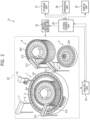
- an analysis apparatus 21 includes an analysis mechanism 22, an analysis mechanism control unit 23, an analysis unit 24, a display unit 25, an operation unit 26, a storage unit 27, and a system control unit 28.
- the analysis mechanism 22 is operated in accordance with control by the analysis mechanism control unit 23.
- the analysis mechanism 22 is arranged in a casing in the analysis apparatus 21.
- the analysis mechanism 22 has mounted thereto a reaction disc 1, a sample disc 2, a polymer accommodation tank 3, a reagent tank 4, a sample arm 5-1, a sample probe 6-1, a polymer loading arm 5-2, a polymer loading probe 6-2, a reagent arm 5-3, a reagent probe 6-3, a stirring arm 7, a stirring bar 8, a photometric mechanism 9, and a washing mechanism 10.
- the reaction disc 1 holds a plurality of glass vessels 101 arranged on its circumference.
- the reaction disc 1 alternately repeats rotation and stop at predetermined time intervals.
- the sample disc 2 is arranged in the vicinity of the reaction disc 1.
- the sample disc 2 holds a sample vessel 201 in which the sample containing the target substance is accommodated.
- the sample disc 2 rotates so that the sample vessel 201 in which the sample containing the target substance is accommodated is arranged at a sample suction position.
- the polymer accommodation tank 3 holds a plurality of polymer accommodation vessels 301 in each of which the hydrophilic polymer is accommodated.
- the polymer accommodation tank 3 rotates so that the polymer accommodation vessel 301 in which the hydrophilic polymer to be dispensed is accommodated is arranged at a polymer suction position.
- the reagent tank 4 is arranged in the vicinity of the reaction disc 1.
- the reagent tank 4 holds a plurality of reagent vessels 401 in each of which the reagent is accommodated.
- the reagent tank 4 rotates so that the reagent vessel 401 in which the reagent to be dispensed is accommodated is arranged at a reagent suction position.
- the sample arm 5-1 is arranged between the reaction disc 1 and the sample disc 2.
- the sample probe 6-1 is attached to the tip of the sample arm 5-1.
- the sample arm 5-1 supports the sample probe 6-1 in a vertically movable manner.
- the sample arm 5-1 supports the sample probe 6-1 in a pivotable manner along a pivot track in an ark shape.
- the pivot track of the sample probe 6-1 passes the sample suction position above the sample disc 2 and a sample discharge position above the reaction disc 1.
- the sample probe 6-1 suctions the sample from the sample vessel 201 arranged at the sample suction position above the sample disc 2, and discharges the sample into the glass vessel 101 arranged at the sample discharge position above the reaction disc 1.
- the polymer loading arm 5-2 is arranged in the vicinity of the outer periphery of the reaction disc 1.
- the polymer loading probe 6-2 is attached to the tip of the polymer loading arm 5-2.
- the polymer loading arm 5-2 supports the polymer loading probe 6-2 in a vertically movable manner.
- the polymer loading arm 5-2 supports the polymer loading probe 6-2 in a pivotable manner along a pivot track in an ark shape.
- the pivot track of the polymer loading probe 6-2 passes the polymer suction position above the polymer accommodation tank 3 and a polymer discharge position above the reaction disc 1.
- the polymer loading probe 6-2 suctions the hydrophilic polymer from the polymer accommodation vessel 301 arranged at the polymer suction position above the polymer accommodation tank 3, and discharges the hydrophilic polymer into the glass vessel 101 arranged at the polymer discharge position above the reaction disc 1.
- the reagent arm 5-3 is arranged between the reaction disc 1 and the reagent tank 4.
- the reagent probe 6-3 is attached to the tip of the reagent arm 5-3.
- the reagent arm 5-3 supports the reagent probe 6-3 in a vertically movable manner.
- the reagent arm 5-3 supports the reagent probe 6-3 in a pivotable manner along a pivot track in an ark shape.
- the pivot track of the reagent probe 6-3 passes the reagent suction position above the reagent tank 4 and a reagent discharge position above the reaction disc 1.
- the reagent probe 6-3 suctions the reagent from the reagent vessel 401 arranged at the reagent suction position above the reagent tank 4, and discharges the reagent into the glass vessel 101 arranged at the reagent discharge position above the reaction disc 1.
- the stirring arm 7 is arranged in the vicinity of the outer periphery of the reaction disc 1.
- the stirring bar 8 is attached to the tip of the stirring arm 7.
- the stirring arm 7 supports the stirring bar 8 in a vertically movable manner.
- the stirring arm 7 supports the stirring bar 8 in a pivotable manner along a pivot track in an ark shape.
- the stirring bar 8 stirs a liquid containing the sample and the reagent in the glass vessel 101 arranged at a stirring position above the reaction disc 1.
- the glass vessel 101 is a vessel for accommodating the reaction liquid. It is desired that, out of the surfaces of the glass vessel 101, at least a light incident surface and a light exit surface be optically transparent and smooth so that optical measurement can be performed by the photometric mechanism 9.
- the liquid amount of the reaction liquid changes in accordance with the amounts of the sample and the reagent, or changes in accordance with a test item.
- the reaction liquid is accommodated in the glass vessel 101 in a liquid amount between the minimum liquid amount and the maximum liquid amount.
- the maximum liquid amount is a liquid amount set for the analysis apparatus 21, and is the maximum liquid amount of the reaction liquid that can be tested.
- the minimum liquid amount is a liquid amount set for the analysis apparatus 21, and is the minimum liquid amount of the reaction liquid that can be tested.
- the photometric mechanism 9 is arranged in the vicinity of the reaction disc 1.
- the photometric mechanism 9 is operated in accordance with control by the analysis mechanism control unit 23.
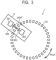
- the photometric mechanism 9 has a light source 901, a detector 902, and polarizers 903.
- the light source 901 radiates light toward the reaction liquid in the glass vessel 101 located at a photometric position in the reaction disc 1.
- the glass vessel 101 is pivoted by the reaction disc 1 at predetermined time intervals so that the glass vessel 101 crosses the light, which has been radiated from the light source 901 and passed through the polarizer 903, substantially at a right angle at the photometric position.
- the reaction liquid in the glass vessel 101 is measured by the photometric mechanism 9 every time the glass vessel 101 crosses the photometric position.
- the detector 902 is arranged at a position opposite to the light source 901 across the glass vessel 101 at the photometric position.
- the detector 902 detects light having passed through the polarizer 903 in a luminescence component from the reaction liquid in the glass vessel 101.
- the polarizer 903 on a glass vessel 101 pass side detector 902 side
- two kinds of polarizers that is, a polarizer parallel to the light polarization direction of the polarizer on an excitation light side (light source 901 side) and a polarizer perpendicular thereto are prepared.
- luminescence from the sample may be divided into a plurality of directions with a splitter.
- the light polarization direction of the polarizer 903 on the glass vessel 101 pass side may be switched to enable measurement.
- the detector 902 produces data having measurement values corresponding to the intensities of light having been detected (hereinafter referred to as "photometric data").
- the photometric data having been produced is supplied to the analysis unit 24.
- a halogen lamp, a light-emitting diode (LED), or a laser generator may be used as the light source 901.
- the light radiated from the light source 901 preferably includes light in a wavelength band in which the value for polarization anisotropy of the reaction liquid can be measured.
- the detector 902 converts the intensity of light having been detected into an electrical signal.
- a photomultiplier tube, a photodiode, or an arrayed photomultiplier tube or photodiode is used as the detector 902.
- an optical window or a concentrator may be arranged between the light source 901 and the detector 902 as required.
- the washing mechanism 10 is arranged on the outer periphery of the reaction disc 1.
- the washing mechanism 10 is operated in accordance with control by the analysis mechanism control unit 23. Specifically, a washing nozzle and a drying nozzle are attached to the washing mechanism 10.
- the washing mechanism 10 washes the glass vessel 101 located at a washing position of the reaction disc 1 with the washing nozzle, and dries the glass vessel 101 with the drying nozzle.
- the analysis mechanism control unit 23 operates the respective devices and mechanisms of the analysis mechanism 22 in accordance with control by the system control unit 28.
- the analysis unit 24 calculates the value for polarization anisotropy of the reaction liquid based on the photometric data. In addition, the analysis unit 24 quantitatively analyzes the target substance in accordance with the test item based on the value for polarization anisotropy of the reaction liquid having been calculated.
- the display unit 25 has a display device, such as a CRT display, a liquid crystal display, an organic EL display, or a plasma display.
- the display unit 25 displays analysis results obtained by the analysis unit 24.
- the operation unit 26 receives various commands or information input from an operator via input equipment.
- a pointing device such as a mouse or a trackball, a selection device such as a switch bottom, or an input device such as a keyboard may be appropriately utilized as the input equipment.
- the storage unit 27 stores, for example, an operation program of the analysis apparatus 21.
- the system control unit 28 functions as the center of the analysis apparatus 21.
- the system control unit 28 reads out the operation program from the storage unit 27, and controls the respective units 23, 24, 25, and 27 in accordance with the operation program.
- the present invention provides the following analysis kit as one embodiment.
- the analysis kit is an analysis kit to be used in an analysis method for determining at least any one of: presence or absence of a target substance; and a concentration of the target substance based on polarization anisotropy, the analysis kit including: a reagent that reacts with the target substance; a glass vessel to be used for accommodating a reaction liquid containing: a sample containing the target substance; and the reagent; and a hydrophilic polymer that reacts with a silanol group of the glass vessel, wherein the reagent includes a luminescent reagent having a hydrophilic surface, and the luminescent reagent includes a luminescent particle.
- Polyvinylpyrrolidone (PVP-K30: manufactured by Tokyo Chemical Industry Co., Ltd.) was dissolved in a 2-morpholinoethanesulfonic acid (MES) buffer solution (manufactured by Kishida Chemical Co., Ltd.) having a pH of 7 to prepare a solution A.
- MES 2-morpholinoethanesulfonic acid
- the mixed solution B was added into a four-necked flask containing the solution A, and the mixture was stirred with a mechanical stirrer set to 300 rpm. After 15 minutes of stirring under a nitrogen flow condition, the temperature of an oil bath that had been prepared was set to 70°C, and the nitrogen flow was performed for an additional 15 minutes. After the mixture had been heated and stirred, an aqueous solution having dissolved therein potassium persulfate (hereinafter abbreviated as "KPS”) (manufactured by Sigma-Aldrich) was added into the reaction solution, and emulsion polymerization was performed for 20 hours.
- KPS potassium persulfate
- the resultant suspension was subjected to ultrafiltration with about 4 L of ion-exchanged water through use of an ultrafiltration membrane having a molecular weight cutoff of 100K so that the product was washed.
- a dispersion of a luminescent reagent was obtained.
- the dispersion was washed with a MES buffer solution having a pH of 5.0, an anti-CRP antibody was added at 100 ⁇ g/mL, and the anti-CRP antibody was bonded to the particles at 25°C for 2 hours.
- the particles were washed with a Tris buffer solution having a pH of 8.
- the particles were washed with a phosphate buffer solution to provide an anti-CRP antibody-modified luminescent reagent having a concentration of 0.3 mass% (sometimes referred to as "affinity particles").
- the bonding of the antibody to the particles was recognized by measuring the amount of a reduction in antibody concentration in the buffer solution having added thereto the antibody by BCA assay.
- the resultant luminescent reagent was diluted with a phosphate (PBS) buffer solution having a pH of 7.4 so as to have a concentration of 0.1 mg/mL to prepare a luminescent reagent liquid.
- PBS phosphate
- a 4-(2-hydroxyethyl)-1-piperazineethanesulfonic acid (HEPES) buffer solution and a PBS buffer solution were mixed at a ratio of 1:1 in terms of volume ratio to prepare a diluent.
- HEPES 4-(2-hydroxyethyl)-1-piperazineethanesulfonic acid
- a liquid which was obtained by dissolving polyvinylpyrrolidone (weight-average molecular weight: about 40,000) in the luminescent reagent liquid so as to have a concentration of 0.0625 mass%, was loaded into a quartz glass cell by 2 mL, and was subjected to immersion for 72 hours. After the immersion, the luminescent reagent liquid was removed, and the glass cell was rinsed with pure water several times. After the washing, measurement was performed through use of the apparatus 1 described later.
- a liquid which was obtained by dissolving polyvinylpyrrolidone (weight-average molecular weight: about 40,000) in the luminescent reagent liquid so as to have a concentration of 0.03125 mass%, was loaded into a quartz glass cell by 2 mL, and was subjected to immersion for 72 hours. After the immersion, the luminescent reagent liquid was removed, and the glass cell was rinsed with pure water several times. After the washing, measurement was performed through use of the apparatus 1 described later.
- the luminescent reagent liquid was loaded into a quartz glass cell by 2 mL, and was subjected to immersion for 72 hours. After the immersion, the luminescent reagent liquid was removed, and the glass cell was rinsed with pure water several times. After the washing, measurement was performed through use of the apparatus 1 described later.
- the luminescent reagent liquid was loaded into a quartz glass cell by 2 mL, and was subjected to immersion for 72 hours. After the immersion, the luminescent reagent liquid was removed, and the glass cell was rinsed with pure water several times. After the washing, measurement was performed through use of the apparatus 1 described later.
- the luminescent reagent liquid was loaded into a polymethyl methacrylate cell by 2 mL, and was subjected to immersion for 72 hours. After the immersion, the luminescent reagent liquid was removed, and the glass cell was rinsed with pure water several times. After the washing, measurement was performed through use of the apparatus 1 described later.
- the "r" in the equation (1) was measured.
- the investigation was performed at a concentration of a CRP antigen of from 0 pM to 200 pM.
- the amount of change in "r” with respect to the concentration of the CRP antigen corresponds to a value obtained by dividing the amount (dr) of change, which is obtained by subtracting the average value of "r”s each obtained through measurement immediately after mixing from the average value of "r”s each obtained through measurement after performing the reaction for 10 minutes, by the time (10 minutes, dt).
- the measurement was performed through use of an apparatus 2 described later.
- the shape of the resultant luminescent reagent was measured with an electron microscope (S-5500 manufactured by Hitachi High-Technologies Corporation).
- the average particle diameter of the luminescent reagent was measured by using dynamic light scattering (Zetasizer Nano S manufactured by Malvern).
- the concentration of a suspension having the luminescent reagent dispersed therein was measured with a gravimetric analyzer (Thermo plus TG8120 manufactured by Rigaku Corporation).
- the apparatus 1 and the apparatus 2 were each used for measurement for performance evaluation.
- the apparatus 1 was an apparatus having such a configuration as described below, and measurement described below was performed.
- An LED light source of excitation light at 340 nm was prepared, and a polarizing filter (NSPFU-30C, manufactured by Sigmakoki Co., Ltd.) and a shortpass filter (84-706, manufactured by Edmund Optics) were inserted into an optical path to set an optical system capable of irradiating a 1 cm quartz square cell.
- a polarizing filter (PIVISC050, manufactured by Thorlabs, Inc.) and a bandpass filter (FB610-10, manufactured by Thorlabs, Inc.) were set in a direction of 90° with respect to incident light.
- the apparatus 2 was an apparatus having such a configuration as described below, and measurement described below was performed.
- An LED light source of excitation light at 340 nm was prepared, and a polarizing filter (NSPFU-30C, manufactured by Sigmakoki Co., Ltd.) and a shortpass filter (84-706, manufactured by Edmund Optics) were inserted into an optical path to set an optical system capable of irradiating a quartz cell having an optical path length of 5 mm.
- a polarizing filter NSPFU-30C, manufactured by Sigmakoki Co., Ltd.
- 84-706 manufactured by Edmund Optics
- the polarized light was separated into two directions by setting an excitation light cut filter (33-910, manufactured by Edmund Optics), a polarizing beamsplitter (47-127, manufactured by Edmund Optics), and a polarizer (SPF-30C-32, manufactured by Sigmakoki Co., Ltd.) in the stated order in the optical path in a straight line with the excitation light across the sample.
- the separated polarized luminescence (in each of the two directions) was detected with an avalanche photodiode (APD, C15522-3010SA, manufactured by Hamamatsu Photonics K.K.). Temperature control was set for a sample holder so as to enable measurement at 37°C.
- Measurement of signals of the polarized luminescence was performed with the LED light source being fixed at an output of 60 mW and a cumulative time being set to 8 milliseconds.
- the resultant signals of the polarized luminescence were measured with an oscilloscope, and were substituted into the equation (1) to determine "r".
- the "r” is a value (R) for polarization anisotropy. The amount of change between "r” immediately after mixing between the luminescent reagent liquid and the CRP antigen liquid and "r" after immersion for 10 minutes from the mixing was calculated.
- the synthesized luminescent reagent had a particle diameter of about 100 nm, and showed strong red luminescence with excitation light at 340 nm.
- the change in absorbance was equal to or less than the specific numerical value, and hence it was recognized that the particles were capable of suppressing nonspecific adsorption.
- Example 5 it was able to be recognized that the "r" derived from the equation (1) and the CRP concentration correlated to each other.
- Example 5 The results of the "r” in Example 5 are shown in Table 2. As shown in Table 2, it was recognized that the "r” was increased in accordance with the CRP concentration. Between 0 pM and 100 pM, it can be recognized that the CRP concentration and the change in slope (dr/dt), which is obtained by dividing the amount of change in "r” over 10 minutes by the time, particularly highly correlate to each other. It was recognized that when the CRP concentration was increased up to 200 pM, a prozone, in which a change in polarization anisotropic property was saturated, was reached, and hence the correlation was reduced.
- the measurement method according to each Example of the present invention was a method capable of repeatedly measuring the concentration of the CRP antigen serving as a target substance with high sensitivity while suppressing noise, such as the adhesion of the luminescent particles onto the glass cell.
- the presence or absence of the target substance or the concentration thereof can be stably measured with high sensitivity. It is conceived that the use of the measurement method according to each Example of the present invention can achieve an apparatus for stably performing measurement with high sensitivity in an application such as a specimen test in which mass testing is performed through repeated use of a glass cell.
- an analysis method for calculating the concentration of a target substance through use of a reagent that reacts with the target substance particularly a method, such as a method based on polarization anisotropy, capable of reducing noise by suppressing nonspecific adsorption of the reagent onto a glass vessel when high-sensitivity measurement is performed through use of a small amount of luminescent particles.
Landscapes
- Health & Medical Sciences (AREA)
- Chemical & Material Sciences (AREA)
- Immunology (AREA)
- Life Sciences & Earth Sciences (AREA)
- Physics & Mathematics (AREA)
- Analytical Chemistry (AREA)
- General Health & Medical Sciences (AREA)
- Biochemistry (AREA)
- General Physics & Mathematics (AREA)
- Pathology (AREA)
- Nuclear Medicine, Radiotherapy & Molecular Imaging (AREA)
- Hematology (AREA)
- Engineering & Computer Science (AREA)
- Biomedical Technology (AREA)
- Molecular Biology (AREA)
- Urology & Nephrology (AREA)
- Chemical Kinetics & Catalysis (AREA)
- Cell Biology (AREA)
- Biotechnology (AREA)
- Microbiology (AREA)
- Food Science & Technology (AREA)
- Medicinal Chemistry (AREA)
- Clinical Laboratory Science (AREA)
- Optics & Photonics (AREA)
- Dispersion Chemistry (AREA)
- Investigating Or Analysing Materials By The Use Of Chemical Reactions (AREA)
Applications Claiming Priority (1)
| Application Number | Priority Date | Filing Date | Title |
|---|---|---|---|
| JP2023147242A JP2025040358A (ja) | 2023-09-11 | 2023-09-11 | 標的物質の濃度を算出する解析方法、解析装置および解析キット |
Publications (1)
| Publication Number | Publication Date |
|---|---|
| EP4521099A1 true EP4521099A1 (fr) | 2025-03-12 |
Family
ID=92708426
Family Applications (1)
| Application Number | Title | Priority Date | Filing Date |
|---|---|---|---|
| EP24198598.5A Pending EP4521099A1 (fr) | 2023-09-11 | 2024-09-05 | Procédé d'analyse, appareil d'analyse et kit d'analyse pour calculer la concentration d'une substance cible |
Country Status (4)
| Country | Link |
|---|---|
| US (1) | US20250085223A1 (fr) |
| EP (1) | EP4521099A1 (fr) |
| JP (1) | JP2025040358A (fr) |
| CN (1) | CN119595599A (fr) |
Citations (8)
| Publication number | Priority date | Publication date | Assignee | Title |
|---|---|---|---|---|
| EP0197425A2 (fr) * | 1985-04-11 | 1986-10-15 | Abbott Laboratories | Analyseur néphelométrique |
| EP0355738A2 (fr) * | 1988-08-26 | 1990-02-28 | Hitachi, Ltd. | Flurophotométre employé dans un équipment automatique pour analyse chimique pour mesurer l'intensité de fluorescence dans l'équipement automatique |
| JPH0352575B2 (fr) | 1981-01-09 | 1991-08-12 | Abbott Lab | |
| US5627522A (en) * | 1992-03-27 | 1997-05-06 | Abbott Laboratories | Automated liquid level sensing system |
| JP2893772B2 (ja) | 1989-12-19 | 1999-05-24 | 三菱化学株式会社 | 免疫測定法 |
| US20140256595A1 (en) * | 2006-01-11 | 2014-09-11 | Raindance Technologies, Inc. | Microfluidic devices and methods of use in the formation and control of nanoreactors |
| US20140271369A1 (en) * | 2013-03-15 | 2014-09-18 | Abbott Laboratories | System and Method for Processing Both Clinical Chemistry and Immunoassay Tests |
| WO2022259946A1 (fr) * | 2021-06-08 | 2022-12-15 | キヤノン株式会社 | Procédé de détection et de mesure d'une substance cible sur la base de la mesure d'anisotropie de polarisation, et particules utilisées à cet effet |
-
2023
- 2023-09-11 JP JP2023147242A patent/JP2025040358A/ja active Pending
-
2024
- 2024-08-23 US US18/813,299 patent/US20250085223A1/en active Pending
- 2024-09-05 EP EP24198598.5A patent/EP4521099A1/fr active Pending
- 2024-09-10 CN CN202411263062.1A patent/CN119595599A/zh active Pending
Patent Citations (8)
| Publication number | Priority date | Publication date | Assignee | Title |
|---|---|---|---|---|
| JPH0352575B2 (fr) | 1981-01-09 | 1991-08-12 | Abbott Lab | |
| EP0197425A2 (fr) * | 1985-04-11 | 1986-10-15 | Abbott Laboratories | Analyseur néphelométrique |
| EP0355738A2 (fr) * | 1988-08-26 | 1990-02-28 | Hitachi, Ltd. | Flurophotométre employé dans un équipment automatique pour analyse chimique pour mesurer l'intensité de fluorescence dans l'équipement automatique |
| JP2893772B2 (ja) | 1989-12-19 | 1999-05-24 | 三菱化学株式会社 | 免疫測定法 |
| US5627522A (en) * | 1992-03-27 | 1997-05-06 | Abbott Laboratories | Automated liquid level sensing system |
| US20140256595A1 (en) * | 2006-01-11 | 2014-09-11 | Raindance Technologies, Inc. | Microfluidic devices and methods of use in the formation and control of nanoreactors |
| US20140271369A1 (en) * | 2013-03-15 | 2014-09-18 | Abbott Laboratories | System and Method for Processing Both Clinical Chemistry and Immunoassay Tests |
| WO2022259946A1 (fr) * | 2021-06-08 | 2022-12-15 | キヤノン株式会社 | Procédé de détection et de mesure d'une substance cible sur la base de la mesure d'anisotropie de polarisation, et particules utilisées à cet effet |
Non-Patent Citations (2)
| Title |
|---|
| CIACO STEFANO ET AL: "Inhibitors of UHRF1 base flipping activity showing cytotoxicity against cancer cells", BIOORGANIC CHEMISTRY, ACADEMIC PRESS INC., NEW YORK, NY, US, vol. 137, 22 May 2023 (2023-05-22), XP087335733, ISSN: 0045-2068, [retrieved on 20230522], DOI: 10.1016/J.BIOORG.2023.106616 * |
| KIM ET AL: "Fabrication and characterization of a PDMS-glass hybrid continuous-flow PCR chip", BIOCHEMICAL ENGINEERING JOURNAL, ELSEVIER, AMSTERDAM, NL, vol. 29, no. 1-2, 1 April 2006 (2006-04-01), pages 91 - 97, XP005335973, ISSN: 1369-703X, DOI: 10.1016/J.BEJ.2005.02.032 * |
Also Published As
| Publication number | Publication date |
|---|---|
| CN119595599A (zh) | 2025-03-11 |
| US20250085223A1 (en) | 2025-03-13 |
| JP2025040358A (ja) | 2025-03-24 |
Similar Documents
| Publication | Publication Date | Title |
|---|---|---|
| JP5652393B2 (ja) | Spfs−lpfs系による測定方法に供するプラズモン励起センサおよびアッセイ法 | |
| US20240118207A1 (en) | Method for detecting and measuring target substance on basis of measurement of polarization anisotropy, and particles used therefor | |
| EP4032938A1 (fr) | Particules et procédé de production de particules | |
| JP4853666B2 (ja) | 標的物質の検出方法、混合粒子、および標的物質の検出試薬 | |
| EP4521099A1 (fr) | Procédé d'analyse, appareil d'analyse et kit d'analyse pour calculer la concentration d'une substance cible | |
| JP5088471B2 (ja) | 標的物質の検出方法およびラテックス凝集反応用試薬 | |
| JP2023168266A (ja) | 偏光異方に基づく測定による解析方法及び解析装置 | |
| JP2023168243A (ja) | 偏光異方に基づく測定による解析方法、検査キット及び検査試薬 | |
| JP5288349B2 (ja) | 免疫学的分析試薬及び免疫学的分析方法 | |
| JP5288348B2 (ja) | 高分子微粒子の製造方法 | |
| EP4509820A1 (fr) | Procédé d'analyse et dispositif d'analyse utilisant une mesure basée sur l'anisotropie de polarisation | |
| US12566139B2 (en) | Method analysis employing measurement based on polarization anisotropy | |
| EP4435048A1 (fr) | Particules pour examens d'échantillon | |
| EP4349887A1 (fr) | Particules électroluminescentes polarisées pour inspection d'échantillon | |
| EP4276447A1 (fr) | Procédé d'analyse impliquant une mesure basée sur l'anisotropie de polarisation, kit de test et réactif de test | |
| JP2023168250A (ja) | 偏光異方に基づく測定による解析方法及び解析装置 | |
| US20250180554A1 (en) | Resin particle and affinity particle including the same | |
| CN117054350A (zh) | 包括基于偏振各向异性的测量的分析方法、测试试剂盒和测试试剂 | |
| JP2023079190A (ja) | 検体検査用粒子 | |
| CN118318006A (zh) | 试样检查用颗粒 | |
| JP7486978B2 (ja) | 検査薬、検査キットおよび検査方法 | |
| JP2025090532A (ja) | 樹脂粒子、及びそれを有するアフィニティー粒子 | |
| WO2026058935A1 (fr) | Méthode de détection de substance cible et kit de test de substance cible | |
| JP2026053299A (ja) | 標的物質の検出方法及び標的物質の検査キット | |
| JP2008215816A (ja) | 免疫診断用中空ポリマー粒子およびその製造方法、ならびに免疫診断用試薬 |
Legal Events
| Date | Code | Title | Description |
|---|---|---|---|
| PUAI | Public reference made under article 153(3) epc to a published international application that has entered the european phase |
Free format text: ORIGINAL CODE: 0009012 |
|
| STAA | Information on the status of an ep patent application or granted ep patent |
Free format text: STATUS: THE APPLICATION HAS BEEN PUBLISHED |
|
| AK | Designated contracting states |
Kind code of ref document: A1 Designated state(s): AL AT BE BG CH CY CZ DE DK EE ES FI FR GB GR HR HU IE IS IT LI LT LU LV MC ME MK MT NL NO PL PT RO RS SE SI SK SM TR |
|
| STAA | Information on the status of an ep patent application or granted ep patent |
Free format text: STATUS: REQUEST FOR EXAMINATION WAS MADE |
|
| 17P | Request for examination filed |
Effective date: 20250912 |