EP4521379A1 - Akustischer warnsignalgenerator für ein fahrzeug - Google Patents
Akustischer warnsignalgenerator für ein fahrzeug Download PDFInfo
- Publication number
- EP4521379A1 EP4521379A1 EP23195530.3A EP23195530A EP4521379A1 EP 4521379 A1 EP4521379 A1 EP 4521379A1 EP 23195530 A EP23195530 A EP 23195530A EP 4521379 A1 EP4521379 A1 EP 4521379A1
- Authority
- EP
- European Patent Office
- Prior art keywords
- vru
- vehicle
- acoustic
- alert signal
- characteristic
- Prior art date
- Legal status (The legal status is an assumption and is not a legal conclusion. Google has not performed a legal analysis and makes no representation as to the accuracy of the status listed.)
- Pending
Links
Images



Classifications
-
- G—PHYSICS
- G08—SIGNALLING
- G08G—TRAFFIC CONTROL SYSTEMS
- G08G1/00—Traffic control systems for road vehicles
- G08G1/16—Anti-collision systems
- G08G1/161—Decentralised systems, e.g. inter-vehicle communication
- G08G1/162—Decentralised systems, e.g. inter-vehicle communication event-triggered
-
- G—PHYSICS
- G08—SIGNALLING
- G08G—TRAFFIC CONTROL SYSTEMS
- G08G1/00—Traffic control systems for road vehicles
- G08G1/16—Anti-collision systems
- G08G1/161—Decentralised systems, e.g. inter-vehicle communication
-
- G—PHYSICS
- G08—SIGNALLING
- G08G—TRAFFIC CONTROL SYSTEMS
- G08G1/00—Traffic control systems for road vehicles
- G08G1/01—Detecting movement of traffic to be counted or controlled
- G08G1/0104—Measuring and analyzing of parameters relative to traffic conditions
-
- B—PERFORMING OPERATIONS; TRANSPORTING
- B60—VEHICLES IN GENERAL
- B60Q—ARRANGEMENT OF SIGNALLING OR LIGHTING DEVICES, THE MOUNTING OR SUPPORTING THEREOF OR CIRCUITS THEREFOR, FOR VEHICLES IN GENERAL
- B60Q5/00—Arrangement or adaptation of acoustic signal devices
- B60Q5/005—Arrangement or adaptation of acoustic signal devices automatically actuated
- B60Q5/006—Arrangement or adaptation of acoustic signal devices automatically actuated indicating risk of collision between vehicles or with pedestrians
-
- B—PERFORMING OPERATIONS; TRANSPORTING
- B60—VEHICLES IN GENERAL
- B60Q—ARRANGEMENT OF SIGNALLING OR LIGHTING DEVICES, THE MOUNTING OR SUPPORTING THEREOF OR CIRCUITS THEREFOR, FOR VEHICLES IN GENERAL
- B60Q9/00—Arrangement or adaptation of signal devices not provided for in one of main groups B60Q1/00 - B60Q7/00, e.g. haptic signalling
- B60Q9/008—Arrangement or adaptation of signal devices not provided for in one of main groups B60Q1/00 - B60Q7/00, e.g. haptic signalling for anti-collision purposes
-
- G—PHYSICS
- G06—COMPUTING OR CALCULATING; COUNTING
- G06V—IMAGE OR VIDEO RECOGNITION OR UNDERSTANDING
- G06V20/00—Scenes; Scene-specific elements
- G06V20/50—Context or environment of the image
- G06V20/56—Context or environment of the image exterior to a vehicle by using sensors mounted on the vehicle
- G06V20/58—Recognition of moving objects or obstacles, e.g. vehicles or pedestrians; Recognition of traffic objects, e.g. traffic signs, traffic lights or roads
-
- G—PHYSICS
- G08—SIGNALLING
- G08G—TRAFFIC CONTROL SYSTEMS
- G08G1/00—Traffic control systems for road vehicles
- G08G1/01—Detecting movement of traffic to be counted or controlled
- G08G1/04—Detecting movement of traffic to be counted or controlled using optical or ultrasonic detectors
-
- G—PHYSICS
- G08—SIGNALLING
- G08G—TRAFFIC CONTROL SYSTEMS
- G08G1/00—Traffic control systems for road vehicles
- G08G1/16—Anti-collision systems
- G08G1/166—Anti-collision systems for active traffic, e.g. moving vehicles, pedestrians, bikes
Definitions
- the present disclosure relates to a method and apparatus for generating a vehicle acoustic alert signal.
- An Acoustic Vehicle Alerting System is designed to emit vehicle warning sounds and alert vulnerable road users (VRUs) of the presence of vehicles.
- An AVAS is especially deemed important in electric drive vehicles that are much less noisy than current vehicles.
- An AVAS can be seen as an audio-centric external human machine interface (eHMI) needed for a vehicle to communicate with VRUs.
- eHMI audio-centric external human machine interface
- Some AVAS systems use sound on a continuous basis to alert pedestrians of the presence of the vehicle when it is being driven at a low speed. Such systems have the adverse effect of increased sound pollution which may be addressed for example using automotive camera/radar to detect the presence of a VRU in the path of the vehicle and then actuating the AVAS.
- a method of generating a vehicle acoustic alert signal for a vehicle comprising an acoustic vehicle alerting system and a RF transceiver the method comprising: detecting an object; classifying the object; and in response to classifying the object as a vulnerable road user: determining at least one VRU characteristic; generating an acoustic alert signal dependent on the at least one VRU characteristic; wirelessly transmitting via the RF transceiver the at least one VRU characteristic to a further vehicle; and transmitting the acoustic alert signal via the AVAS.
- the method comprises: wirelessly receiving at least one further VRU characteristic from the further vehicle; and generating the acoustic alert signal to be audibly distinct from a further acoustic alert signal generated by the further vehicle dependent on the at least one VRU characteristic and at least one further VRU characteristic.
- the acoustic alert signal is generated dependent on a distance between the vehicle and the VRU and a further distance between the further vehicle and the VRU.
- the at least one VRU characteristic comprises a range of the vehicle from the VRU and the at least one further VRU characteristic comprises the range of the further vehicle from the VRU.
- generating the acoustic alert signal to be audibly distinct from the further acoustic alert signal further comprises time domain interleaving the acoustic alert signal with respect to the further acoustic alert signal.
- generating the acoustic signal adapted to be audibly distinct from the further acoustic alert signal further comprises frequency domain interleaving the acoustic signal with respect to the further acoustic alert signal.
- generating the acoustic signal adapted to be audibly distinct from the further acoustic alert signal further comprises adapting a sound power level of the acoustic signal dependent on the distance between the vehicle and the VRU.
- the at least one VRU characteristic comprises a speed value.
- the at least one VRU characteristic comprises a direction of motion value.
- generating the acoustic alert signal further comprises beamforming the acoustic alert signal dependent on the at least one VRU characteristic.
- detecting an object and classifying the object further comprises providing a detection system configured to detect and classify objects external to the vehicle.
- the detection system is located in the vehicle.
- the detection system is located at a fixed point external to the vehicle.
- the detection system comprises one of a radar, lidar and camera.
- an apparatus comprising: an acoustic vehicle alerting system located in a vehicle, the AVAS comprising; a processor; an acoustic emitter array coupled to the processor; an RF transceiver coupled to the processor; an object detection system coupled to the AVAS, the object detection system comprising: a detector; and an object classifier having an object classifier input coupled to the detector and an object classifier output coupled to the processor; wherein the object detection system is configured to detect an object; classify the object; and in response to classifying the object as a vulnerable road user, VRU, determine at least one VRU characteristic; and wherein the processor is configured to generate an acoustic alert signal dependent on the at least one VRU characteristic; wirelessly transmit via the RF transceiver the at least one VRU characteristic to a further vehicle; and transmit the acoustic alert signal via the AVAS.
- the processor is configured to : wirelessly receive at least one further VRU characteristic from the further vehicle; and generate the acoustic alert signal to be audibly distinct from a further acoustic alert signal generated by the further vehicle dependent on the at least one VRU characteristic and at least one further VRU characteristic.
- the processor is configured to generate the acoustic alert signal dependent on a distance between the vehicle and the VRU and a further distance between the further vehicle and the VRU.
- FIG. 1 shows a vehicle 100 including a detection system 110 and an acoustic vehicle alerting system 130 according to an embodiment.
- the detection system 110 includes a detector 104 having a detection input 102 and a detection output 106 connected to an object classifier input of object classifier 108.
- the object classifier 108 has an object classifier output connected to the detection system output 112.
- the AVAS 130 includes a processor 120 having an input connected to the detection system output 112 and a processor output 116 connected to an acoustic emitter array 124.
- the acoustic emitter array 124 may include one or more loudspeakers or other acoustic transducers which may be arranged as a co-located array or distributed around the vehicle 100.
- the processor 120 may also be connected via connection 114 to an RF transceiver 118 and associated antenna 122. Examples of a vehicle in this context include but are not limited to an automobile, van, truck, and motorcycle.
- the detector 104 may be implemented for example using radar, lidar or camera.
- the object classifier 108 may be implemented for example using a machine learning model.
- the processor 120 may be implemented in hardware, software or a combination of hardware and software.
- FIG. 2 shows an apparatus 150 including an acoustic vehicle alerting system 180 for a vehicle according to an embodiment.
- Apparatus 150 includes a detection system 160 which may be at a fixed location, for example included in a mobile cellular network base station.
- the detection system 160 includes a detector 154 having a detection input 152 and detection output 156 connected to an object classifier input of an object classifier 158.
- the object classifier 158 has an object classifier output 162 connected to the input of a transceiver 176 and associated antenna 178.
- the AVAS 180 is located in a vehicle and includes a processor 170 having an input connected to the detection system output 112 and a processor output 166 connected to an acoustic emitter array 174.
- the acoustic emitter array 174 may include one or more loudspeakers or other acoustic transducers.
- the processor 170 may also be connected via connection 164 to an RF transceiver 168 and associated antenna 172.
- the detection system 160 may be wirelessly connected by wireless connection 182 to the AVAS system 180 via respective transceivers 176, 168 and antennas 178,172.
- FIG. 3 shows a method of generating an acoustic vehicle alert 200 for a vehicle comprising an acoustic vehicle alerting system according to an embodiment.
- the method 200 may be implemented for example by vehicle 100 or apparatus 150.
- an object may be detected for example by detector 104, 154 and classified in step 204 for example by object classifier 108, 158 which may be implemented as a machine learning model.
- the method 200 may check whether the detected object is classified as a vulnerable road user (VRU) such as for example a pedestrian or a cyclist. If the object is not classed as a VRU, the method returns to step 202, otherwise the method proceeds to step 208 which generates an acoustic alert signal dependent on at least one VRU characteristic.
- VRU vulnerable road user
- the VRU characteristics may include for example the distance or range of the VRU from the vehicle, the speed of the VRU and the direction of motion of the VRU.
- the acoustic alert signal may be generated with a sound pressure level dependent on the range of the VRU or a frequency spectrum dependent on the speed and/or direction of motion of the VRU.
- the acoustic alert signal may be generated to be audible only in predetermined time slots dependent on the distance of the VRU from the vehicle.
- the acoustic alert signal may be generated within a particular audible frequency range dependent on the distance of the VRU from the vehicle.
- one or more VRU characteristics may be transmitted to a further vehicle for generating an AVAS by the further vehicle.
- the generated acoustic alert signal may be transmitted by the AVAS via for example via the acoustic emitter array 124,174.
- the acoustic alert signal may be further adapted by beamforming dependent on the VRU direction and motion so that the acoustic alert signal is preferentially emitted in a direction towards the VRU.
- the acoustic emitter array may consist of a number of loudspeakers distributed around the vehicle. In these examples, only a subset of the loudspeakers may be actuated depending on the dependent on the VRU direction and motion so that the acoustic alert signal is preferentially emitted in a direction towards the VRU.
- Figure 4 shows a method of generating an acoustic vehicle alert 250 for a vehicle comprising an acoustic vehicle alerting system according to an embodiment.
- the method 250 may be implemented for example by vehicle 100 or apparatus 150.
- an object may be detected for example by detector 104, 154 and classified in step 254 for example by object classifier 108, 158 which may be implemented as a machine learning model.
- the method 250 may check whether the detected object is classified as a VRU and may determine one or more associated VRU characteristics. If the object is not classed as a VRU, the method returns to step 252, otherwise the method proceeds to step 258 where one or more further VRU characteristics of the same VRU detected by a further vehicle may be received from the further vehicle.
- an acoustic alert signal may be generated dependent on one or more VRU characteristics determined by the vehicle and one or more further VRU characteristics determined by the further vehicle.
- the acoustic alert signal may be generated with a sound pressure level dependent on whether or not the vehicle is closer to the VRU than the further vehicle determined from the respective VRU characteristics.
- the acoustic alert signal may be generated with a frequency spectrum dependent on the speed and/or direction of motion of the VRU.
- the acoustic alert signal may be generated to be audible only in predetermined time slots dependent on the relative distance of the VRU from the vehicle and the further vehicle.
- the acoustic alert signal may be generated within a particular audible frequency range dependent on the relative distance of the VRU from the vehicle and the further vehicle.
- the generated acoustic alert signal may be transmitted by the AVAS via for example the acoustic emitter array 124.
- the acoustic alert signal may be further adapted by beamforming dependent on the VRU direction and motion so that the acoustic alert signal is preferentially emitted in a direction towards the VRU.
- FIGS 5A and 5B show an example AVAS system 300 comprising two vehicles 100-1, 100-2 which may be instances of vehicle 100.
- the respective detection system 110 of each of the vehicles 100-1, 100-2 detects objects in the immediate driving environment and perform object classification to determine that a VRU 306 for example a cyclist, pedestrian is present in the vicinity as previously described.
- the second vehicle 100-2 may be in a RF blind spot and so may not detect the presence of the VRU 306.
- the first vehicle 100-1 may detect the VRU and determine VRU characteristics including one or more of a range, speed, direction of motion with respect to the first vehicle 100-1 based on sensing measurements.
- the VRU characteristics determined by the first vehicle 100-1 may be transmitted by wireless connection 302 to the second vehicle 100-2 together with the location of the first vehicle 100-1 for example by transmitting GPS coordinates determined by a GPS receiver located in the first car and coupled to the AVAS (not shown).
- the second vehicle 100-2 may determine the position of the VRU 306 from the received VRU characteristics.
- the first and second vehicles 100-1, 100-2 may transmit respective acoustic alert signals 304, 308 via respective acoustic emitter arrays 124.
- the said actuation by a vehicle alerting system of the vehicles 100-1, 100-2 is in a specified region by beamforming the acoustic signal such that it is directed towards the VRU 306 to alert the VRU of approaching vehicles 100-1, 100-2.
- the AVAS may be generated so that the acoustic emitter arrays 124 are directed to indicate at least one characteristic of motion of the vehicle, for example speed, direction of motion and/or at least one characteristic of vehicle control, for example braking, acceleration, cruise control. This may be achieved for example by varying the pitch and/or sound pressure level of the acoustic alert.
- the sounds transmitted by the acoustic emitter arrays are processed to be perceived by the VRU 306 as spatially distinct acoustical events. This may be achieved by one or more of time domain interleaving, frequency domain interleaving and sound power level (SPL) adaptation as a function of the distance between the acoustic emitters and the VRU 306.
- SPL sound power level
- FIGS 6A and 6B show an example AVAS system 320 comprising two vehicles 100-1, 100-2.
- the AVAS system 320 may include a controller 324 which may be implemented for example by software running on processor 120, 170.
- the controller 324 may have communication links 322, 326 between the vehicles 100-1, 100-2 and allows co-operative signaling between the vehicles 100-1, 100-2 to exchange information on VRU characteristics and determines which acoustic actuations occur in each vehicle 100-1, 100-2 such as for example actuation time and duration and/or and what frequency range to use.
- the respective detection system 110 of each of the vehicles 100-1, 100-2 which may be implemented as a radar system, detects objects in the immediate driving environment and performs object classification to determine that a VRU 332 for example a cyclist, pedestrian is present in the vicinity as previously described.
- the first vehicle 100-1 may detect the VRU and determine VRU characteristics including one or more of a range, speed, direction of motion with respect to the first vehicle 100-1 based on sensing measurements.
- the VRU characteristics determined by the first vehicle 100-1 may be transmitted 334 to the second vehicle 100-2 together with the location of the first vehicle 100-1 for example by transmitting GPS coordinates determined by a GPS receiver located in the first car and coupled to the AVAS (not shown).
- the VRU characteristics determined by the second vehicle 100-2 may be transmitted 336 to the first vehicle 100-1 together with the location of the second vehicle 100-2 for example by transmitting GPS coordinates determined by a GPS receiver located in the second car and coupled to the AVAS (not shown).
- the first and second vehicles 100-1, 100-2 may transmit respective acoustic alert signals 328, 330 via an acoustic emitter array 124.
- the actuation by a vehicle alerting system of the vehicles 100-1, 100-2 in a specified region by beamforming the acoustic signal may be directed towards the VRU 332 to alert the VRU of approaching vehicles 100-1, 100-2 for example by beamforming.
- the sounds transmitted by the acoustic emitter arrays are processed to be perceived by the VRU 332 as spatially distinct acoustical events. This may be achieved by one or more of time domain interleaving, frequency domain interleaving and sound power level (SPL) adaptation as a function of the distance between the acoustic emitters and the VRU 332.
- the controller 324 may determine for example which of the vehicles 100-1, 100-2 transmit in a specific time slot or allocate different frequency bands to the different vehicles 100-1, 100-2.
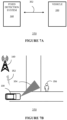
- FIGS 7A and 7B shows an example AVAS system 350 with a single vehicle 100 and a fixed detection system 160.
- the detection system 160 which may for example be implemented as a radar system may detect objects in the immediate driving environment and perform object classification to determine that a VRU 356 is present in the vicinity as previously described.
- the detection system may be omitted from the vehicle and a vehicle may include an AVAS system 180.
- the detection system 160 may detect the VRU and determine VRU characteristics including one or more of a range, speed, direction of motion with respect to the detection system 160 based on sensing measurements.
- the VRU characteristics determined by the detection system 160 may be transmitted 352 to the vehicle 100 together with the location of the detection system 160 for example by transmitting GPS coordinates.
- the vehicle 100 may determine the position of the VRU 356 from the received VRU characteristics.
- the vehicle 100 may transmit an acoustic alert signals 354 via respective acoustic emitter array 124.
- the AVAS of the vehicle 100 may beamform the acoustic signal such that it is directed towards the VRU 356 to alert the VRU of approaching vehicle 100.
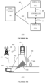
- FIGS 8A and 8B shows an example AVAS system 400 comprising two vehicles 100-1, 100-2 and a fixed detection system 160.
- the detection system may be omitted from vehicles 100-1, 100-2 so for example a vehicle may just include an AVAS system 180.
- the AVAS system 400 may include a controller 412 which may be implemented for example by software running on processor 120, 170 i.e. included as part of the function of the processor 120, 170.
- the controller 412 may have communication links 404, 414 between the vehicles 100-1, 100-2 and allows co-operative signaling between the vehicles 100-1, 100-2 to exchange information on VRU characteristics and determines which acoustic actuations occur in each vehicle 100-1, 100-2 such as for example actuation time and duration and/or and what frequency range to use.
- the detection system 160 may detect the VRU 406 and determine VRU characteristics including one or more of a range, speed, direction of motion with respect to the detection system 160 based on sensing measurements.
- the VRU characteristics determined by the detection system 160 may be transmitted 402 to the vehicles 100-1, 100-2 together with the location of the detection system 160 by for example transmitting GPS coordinates.
- the first and second vehicles 100-1, 100-2 may exchange VRU characteristics and respective location information via link 416.
- the first and second vehicles 100-1, 100-2 may transmit respective acoustic alert signals 408, 410 via respective acoustic emitter arrays 124.
- the transmit respective acoustic alert signals 408, 410 may be confined to a specified region, for example by beamforming the acoustic signal such that it is directed towards the VRU 406.
- the sounds transmitted by the acoustic emitter arrays are processed to be perceived by the VRU 406 as spatially distinct acoustical events. This may be achieved by one or more of time domain interleaving, frequency domain interleaving and sound power level (SPL) adaptation as a function of the distance between the acoustic emitters and the VRU 406.
- the controller 412 may determine for example which of the vehicles 100-1, 100-2 transmit in a specific time slot or allocate different frequency bands to the different vehicles 100-1, 100-2.
- Figure 9 illustrates an example of time-interleaving 450 for two acoustic emitters which can be used for example so that a VRU perceives an alert signal from each acoustic emitter as a spatially distinct acoustical event.
- Graph 452 shows the sound pressure level (SPL) versus time in a normal state for a first acoustic emitter.
- Graph 454 shows the sound pressure level versus time when a VRU is detected for the first acoustic emitter.
- Graph 456 shows the sound pressure level versus time in a normal state for a second acoustic emitter.
- Graph 458 shows the sound pressure level versus time for the second acoustic emitter when a VRU is detected.
- the SPL may be a constant value for both acoustic emitters.
- the first acoustic emitter may transmit in first time slots t1 and the second acoustic emitter may transmit in second non-overlapping time slots t2.
- the time slot to use may be determined for example by the relative distance of the vehicle or vehicles to the VRU. For example, the closest vehicle to the VRU may use the first time slots t1 and the other vehicle may use the second time slots t2. For more than two vehicles, multiple predefined time slots may be defined.
- Figure 10 illustrates an example of frequency-interleaving 470 for two acoustic emitters which can be used for example so a VRU perceives an alert signal from each acoustic emitter as a spatially distinct acoustical event.
- Graph 472 shows the sound pressure level (SPL) versus frequency in a normal state for a first acoustic emitter.
- Graph 474 shows the sound pressure level versus frequency when a VRU is detected for the first acoustic emitter.
- Graph 476 shows the sound pressure level versus frequency in a normal state for a second acoustic emitter indicated by line 480 versus first acoustic emitter shown by line 482.
- a collaborative acoustic vehicle alerting system actuated by a distributed automotive sensing system for alerting vulnerable road users is described.
- the VRU is detected by one or more automotive sensors or an external fixed sensor and information on parameters such as range (distance), velocity and angular information of VRU detected by vehicles or an external detector is exchanged to determine which one or more AVAS to actuate.
- the one or more AVAS may then be actuated for example using time and/or frequency multiplexing in a manner such that the acoustic alert does not enhance acoustic noise and alerts the VRU of distinct approaching vehicles.
- the method and apparatus described may provide a closed-loop distributed AVAS system that uses cooperative perception from multiple vehicles.
- the illustrated embodiments described herein refer to two vehicles. However, in other examples, three or more vehicles including an AVAS may exchange VRU characteristics and generate an AVAS signal in a similar way to that as described in the illustrated embodiments.
- the set of instructions/method steps described above are implemented as functional and software instructions embodied as a set of executable instructions which are effected on a computer or machine which is programmed with and controlled by said executable instructions. Such instructions are loaded for execution on a processor (such as one or more CPUs).
- processor includes microprocessors, microcontrollers, processor modules or subsystems (including one or more microprocessors or microcontrollers), or other control or computing devices.
- a processor can refer to a single component or to plural components.
Landscapes
- Physics & Mathematics (AREA)
- General Physics & Mathematics (AREA)
- Engineering & Computer Science (AREA)
- Mechanical Engineering (AREA)
- Human Computer Interaction (AREA)
- Chemical & Material Sciences (AREA)
- Analytical Chemistry (AREA)
- Multimedia (AREA)
- Theoretical Computer Science (AREA)
- Acoustics & Sound (AREA)
- Traffic Control Systems (AREA)
Priority Applications (3)
| Application Number | Priority Date | Filing Date | Title |
|---|---|---|---|
| EP23195530.3A EP4521379A1 (de) | 2023-09-05 | 2023-09-05 | Akustischer warnsignalgenerator für ein fahrzeug |
| US18/816,127 US12518629B2 (en) | 2023-09-05 | 2024-08-27 | Vehicle acoustic alert signal generator |
| CN202411199616.6A CN119580479A (zh) | 2023-09-05 | 2024-08-29 | 车辆声音警告信号产生器 |
Applications Claiming Priority (1)
| Application Number | Priority Date | Filing Date | Title |
|---|---|---|---|
| EP23195530.3A EP4521379A1 (de) | 2023-09-05 | 2023-09-05 | Akustischer warnsignalgenerator für ein fahrzeug |
Publications (1)
| Publication Number | Publication Date |
|---|---|
| EP4521379A1 true EP4521379A1 (de) | 2025-03-12 |
Family
ID=87933541
Family Applications (1)
| Application Number | Title | Priority Date | Filing Date |
|---|---|---|---|
| EP23195530.3A Pending EP4521379A1 (de) | 2023-09-05 | 2023-09-05 | Akustischer warnsignalgenerator für ein fahrzeug |
Country Status (3)
| Country | Link |
|---|---|
| US (1) | US12518629B2 (de) |
| EP (1) | EP4521379A1 (de) |
| CN (1) | CN119580479A (de) |
Citations (4)
| Publication number | Priority date | Publication date | Assignee | Title |
|---|---|---|---|---|
| DE102013017626A1 (de) * | 2013-10-23 | 2015-04-23 | Audi Ag | Verfahren zur Warnung weiterer Verkehrsteilnehmer vor Fußgängern durch ein Kraftfahrzeug und Kraftfahrzeug |
| DE102016209552A1 (de) * | 2016-06-01 | 2017-12-07 | Robert Bosch Gmbh | Verfahren zum Warnen vor einem Fußgänger in einem Umfeld eines Fahrzeugs im geparkten Zustand und Verfahren zum Steuern eines Fahrzeugs |
| US10315563B1 (en) * | 2018-05-22 | 2019-06-11 | Zoox, Inc. | Acoustic notifications |
| US20210114514A1 (en) * | 2019-10-17 | 2021-04-22 | Zoox, Inc. | Dynamic vehicle warning signal emission |
Family Cites Families (12)
| Publication number | Priority date | Publication date | Assignee | Title |
|---|---|---|---|---|
| US9507346B1 (en) * | 2015-11-04 | 2016-11-29 | Zoox, Inc. | Teleoperation system and method for trajectory modification of autonomous vehicles |
| KR101996415B1 (ko) * | 2016-12-30 | 2019-07-04 | 현대자동차주식회사 | 자세 정보 기반 보행자 탐지 및 보행자 충돌 방지 장치 및 방법 |
| KR102422137B1 (ko) | 2017-06-30 | 2022-07-18 | 현대자동차주식회사 | 친환경 자동차용 보행자 경보 시스템 및 경보 방법 |
| JP7028131B2 (ja) * | 2018-10-10 | 2022-03-02 | トヨタ自動車株式会社 | 報知装置 |
| CN109649266A (zh) * | 2019-01-21 | 2019-04-19 | 北京百度网讯科技有限公司 | 车辆控制方法、装置、计算机设备和存储介质 |
| CN109878513A (zh) * | 2019-03-13 | 2019-06-14 | 百度在线网络技术(北京)有限公司 | 防御性驾驶策略生成方法、装置、设备及存储介质 |
| US11796654B2 (en) * | 2019-09-04 | 2023-10-24 | Qualcomm Incorporated | Distributed sensor calibration and sensor sharing using cellular vehicle-to-everything (CV2X) communication |
| US11577722B1 (en) * | 2019-09-30 | 2023-02-14 | Zoox, Inc. | Hyper planning based on object and/or region |
| WO2021118675A1 (en) * | 2019-12-12 | 2021-06-17 | Intel Corporation | Vulnerable road user safety technologies based on responsibility sensitive safety |
| DE102021101260A1 (de) | 2021-01-21 | 2022-07-21 | Bayerische Motoren Werke Aktiengesellschaft | Kraftfahrzeug mit einem Acoustic Vehicle Alerting System (AVAS) |
| US20210383695A1 (en) * | 2021-06-25 | 2021-12-09 | Intel Corporation | Methods and devices for a road user |
| CN116266431A (zh) * | 2021-12-16 | 2023-06-20 | 通用汽车环球科技运作有限责任公司 | 机动车辆的交叉路口交通告警系统 |
-
2023
- 2023-09-05 EP EP23195530.3A patent/EP4521379A1/de active Pending
-
2024
- 2024-08-27 US US18/816,127 patent/US12518629B2/en active Active
- 2024-08-29 CN CN202411199616.6A patent/CN119580479A/zh active Pending
Patent Citations (4)
| Publication number | Priority date | Publication date | Assignee | Title |
|---|---|---|---|---|
| DE102013017626A1 (de) * | 2013-10-23 | 2015-04-23 | Audi Ag | Verfahren zur Warnung weiterer Verkehrsteilnehmer vor Fußgängern durch ein Kraftfahrzeug und Kraftfahrzeug |
| DE102016209552A1 (de) * | 2016-06-01 | 2017-12-07 | Robert Bosch Gmbh | Verfahren zum Warnen vor einem Fußgänger in einem Umfeld eines Fahrzeugs im geparkten Zustand und Verfahren zum Steuern eines Fahrzeugs |
| US10315563B1 (en) * | 2018-05-22 | 2019-06-11 | Zoox, Inc. | Acoustic notifications |
| US20210114514A1 (en) * | 2019-10-17 | 2021-04-22 | Zoox, Inc. | Dynamic vehicle warning signal emission |
Also Published As
| Publication number | Publication date |
|---|---|
| CN119580479A (zh) | 2025-03-07 |
| US20250078660A1 (en) | 2025-03-06 |
| US12518629B2 (en) | 2026-01-06 |
Similar Documents
| Publication | Publication Date | Title |
|---|---|---|
| US9734699B2 (en) | System for providing alerts to vehicle occupants | |
| US6731204B2 (en) | Object detection system providing driver information through sound | |
| US9911335B2 (en) | Systems and methods for automatically documenting an accident | |
| US8217766B2 (en) | Vehicle presence notification apparatus | |
| JP6540689B2 (ja) | レーダーモジュール、輸送機器、及び物体識別方法 | |
| US11745652B2 (en) | Device and method for controlling sound signal of vehicle, and device of outputting sound signal | |
| CN102294984B (zh) | 基于方向盘震动的车辆障碍物监测方法及装置 | |
| US20160178739A1 (en) | Radar system for vehicle and operating method thereof | |
| JP2008298544A (ja) | 物体検出装置、及び車両用制御装置 | |
| CN108352119A (zh) | 具有车辆到车辆通信能力的用于安静车辆的增强声音生成 | |
| US9640076B2 (en) | Communication device and communication method for a vehicle | |
| US20220236368A1 (en) | Transmission Control Method and Related Device | |
| US12518629B2 (en) | Vehicle acoustic alert signal generator | |
| GB2508734B (en) | Method and device for determining the relative distance and the relative movement of a plurality of traffic participants | |
| JP6131752B2 (ja) | 車両周囲環境報知システム | |
| CN103487799B (zh) | 测速方法及其相关电子装置 | |
| KR20230111619A (ko) | 운전자 보조 장치, 그 제어 방법 및 차량 | |
| JP2001236599A (ja) | 移動体接近状況判別装置、携帯電話端末、移動体動作制御装置、電波発信装置及び移動体接近状況判別方法 | |
| US20100109855A1 (en) | Sounder control circuit, sounder system and method for vehicle | |
| JPH1090406A (ja) | 警報装置 | |
| JP2016001774A (ja) | 音声報知装置 | |
| US20140159885A1 (en) | Blind Spot Detection System | |
| JP5471785B2 (ja) | 走行制御装置 | |
| US20250076499A1 (en) | Ultrasonic object detection | |
| US20250274703A1 (en) | Systems, methods, and devices for automobile environment monitoring and signal steering |
Legal Events
| Date | Code | Title | Description |
|---|---|---|---|
| PUAI | Public reference made under article 153(3) epc to a published international application that has entered the european phase |
Free format text: ORIGINAL CODE: 0009012 |
|
| STAA | Information on the status of an ep patent application or granted ep patent |
Free format text: STATUS: THE APPLICATION HAS BEEN PUBLISHED |
|
| AK | Designated contracting states |
Kind code of ref document: A1 Designated state(s): AL AT BE BG CH CY CZ DE DK EE ES FI FR GB GR HR HU IE IS IT LI LT LU LV MC ME MK MT NL NO PL PT RO RS SE SI SK SM TR |
|
| STAA | Information on the status of an ep patent application or granted ep patent |
Free format text: STATUS: REQUEST FOR EXAMINATION WAS MADE |
|
| 17P | Request for examination filed |
Effective date: 20250912 |