EP4521510A2 - Accessoire de mesure pour batteries - Google Patents
Accessoire de mesure pour batteries Download PDFInfo
- Publication number
- EP4521510A2 EP4521510A2 EP24198723.9A EP24198723A EP4521510A2 EP 4521510 A2 EP4521510 A2 EP 4521510A2 EP 24198723 A EP24198723 A EP 24198723A EP 4521510 A2 EP4521510 A2 EP 4521510A2
- Authority
- EP
- European Patent Office
- Prior art keywords
- strap
- container
- battery
- assembly
- strain gauge
- Prior art date
- Legal status (The legal status is an assumption and is not a legal conclusion. Google has not performed a legal analysis and makes no representation as to the accuracy of the status listed.)
- Pending
Links
Images




Classifications
-
- H—ELECTRICITY
- H01—ELECTRIC ELEMENTS
- H01M—PROCESSES OR MEANS, e.g. BATTERIES, FOR THE DIRECT CONVERSION OF CHEMICAL ENERGY INTO ELECTRICAL ENERGY
- H01M10/00—Secondary cells; Manufacture thereof
- H01M10/42—Methods or arrangements for servicing or maintenance of secondary cells or secondary half-cells
- H01M10/48—Accumulators combined with arrangements for measuring, testing or indicating the condition of cells, e.g. the level or density of the electrolyte
-
- G—PHYSICS
- G01—MEASURING; TESTING
- G01B—MEASURING LENGTH, THICKNESS OR SIMILAR LINEAR DIMENSIONS; MEASURING ANGLES; MEASURING AREAS; MEASURING IRREGULARITIES OF SURFACES OR CONTOURS
- G01B21/00—Measuring arrangements or details thereof, where the measuring technique is not covered by the other groups of this subclass, unspecified or not relevant
- G01B21/02—Measuring arrangements or details thereof, where the measuring technique is not covered by the other groups of this subclass, unspecified or not relevant for measuring length, width, or thickness
-
- G—PHYSICS
- G01—MEASURING; TESTING
- G01L—MEASURING FORCE, STRESS, TORQUE, WORK, MECHANICAL POWER, MECHANICAL EFFICIENCY, OR FLUID PRESSURE
- G01L1/00—Measuring force or stress, in general
- G01L1/20—Measuring force or stress, in general by measuring variations in ohmic resistance of solid materials or of electrically-conductive fluids; by making use of electrokinetic cells, i.e. liquid-containing cells wherein an electrical potential is produced or varied upon the application of stress
- G01L1/22—Measuring force or stress, in general by measuring variations in ohmic resistance of solid materials or of electrically-conductive fluids; by making use of electrokinetic cells, i.e. liquid-containing cells wherein an electrical potential is produced or varied upon the application of stress using resistance strain gauges
- G01L1/2206—Special supports with preselected places to mount the resistance strain gauges; Mounting of supports
-
- G—PHYSICS
- G01—MEASURING; TESTING
- G01L—MEASURING FORCE, STRESS, TORQUE, WORK, MECHANICAL POWER, MECHANICAL EFFICIENCY, OR FLUID PRESSURE
- G01L1/00—Measuring force or stress, in general
- G01L1/20—Measuring force or stress, in general by measuring variations in ohmic resistance of solid materials or of electrically-conductive fluids; by making use of electrokinetic cells, i.e. liquid-containing cells wherein an electrical potential is produced or varied upon the application of stress
- G01L1/22—Measuring force or stress, in general by measuring variations in ohmic resistance of solid materials or of electrically-conductive fluids; by making use of electrokinetic cells, i.e. liquid-containing cells wherein an electrical potential is produced or varied upon the application of stress using resistance strain gauges
- G01L1/2287—Measuring force or stress, in general by measuring variations in ohmic resistance of solid materials or of electrically-conductive fluids; by making use of electrokinetic cells, i.e. liquid-containing cells wherein an electrical potential is produced or varied upon the application of stress using resistance strain gauges constructional details of the strain gauges
-
- G—PHYSICS
- G01—MEASURING; TESTING
- G01L—MEASURING FORCE, STRESS, TORQUE, WORK, MECHANICAL POWER, MECHANICAL EFFICIENCY, OR FLUID PRESSURE
- G01L5/00—Apparatus for, or methods of, measuring force, work, mechanical power, or torque, specially adapted for specific purposes
-
- H—ELECTRICITY
- H01—ELECTRIC ELEMENTS
- H01M—PROCESSES OR MEANS, e.g. BATTERIES, FOR THE DIRECT CONVERSION OF CHEMICAL ENERGY INTO ELECTRICAL ENERGY
- H01M10/00—Secondary cells; Manufacture thereof
- H01M10/42—Methods or arrangements for servicing or maintenance of secondary cells or secondary half-cells
- H01M10/4207—Methods or arrangements for servicing or maintenance of secondary cells or secondary half-cells for several batteries or cells simultaneously or sequentially
-
- H—ELECTRICITY
- H01—ELECTRIC ELEMENTS
- H01M—PROCESSES OR MEANS, e.g. BATTERIES, FOR THE DIRECT CONVERSION OF CHEMICAL ENERGY INTO ELECTRICAL ENERGY
- H01M10/00—Secondary cells; Manufacture thereof
- H01M10/42—Methods or arrangements for servicing or maintenance of secondary cells or secondary half-cells
- H01M10/425—Structural combination with electronic components, e.g. electronic circuits integrated to the outside of the casing
-
- H—ELECTRICITY
- H01—ELECTRIC ELEMENTS
- H01M—PROCESSES OR MEANS, e.g. BATTERIES, FOR THE DIRECT CONVERSION OF CHEMICAL ENERGY INTO ELECTRICAL ENERGY
- H01M10/00—Secondary cells; Manufacture thereof
- H01M10/42—Methods or arrangements for servicing or maintenance of secondary cells or secondary half-cells
- H01M10/4285—Testing apparatus
-
- H—ELECTRICITY
- H01—ELECTRIC ELEMENTS
- H01M—PROCESSES OR MEANS, e.g. BATTERIES, FOR THE DIRECT CONVERSION OF CHEMICAL ENERGY INTO ELECTRICAL ENERGY
- H01M10/00—Secondary cells; Manufacture thereof
- H01M10/42—Methods or arrangements for servicing or maintenance of secondary cells or secondary half-cells
- H01M10/48—Accumulators combined with arrangements for measuring, testing or indicating the condition of cells, e.g. the level or density of the electrolyte
- H01M10/482—Accumulators combined with arrangements for measuring, testing or indicating the condition of cells, e.g. the level or density of the electrolyte for several batteries or cells simultaneously or sequentially
-
- H—ELECTRICITY
- H01—ELECTRIC ELEMENTS
- H01M—PROCESSES OR MEANS, e.g. BATTERIES, FOR THE DIRECT CONVERSION OF CHEMICAL ENERGY INTO ELECTRICAL ENERGY
- H01M10/00—Secondary cells; Manufacture thereof
- H01M10/42—Methods or arrangements for servicing or maintenance of secondary cells or secondary half-cells
- H01M10/48—Accumulators combined with arrangements for measuring, testing or indicating the condition of cells, e.g. the level or density of the electrolyte
- H01M10/486—Accumulators combined with arrangements for measuring, testing or indicating the condition of cells, e.g. the level or density of the electrolyte for measuring temperature
-
- H—ELECTRICITY
- H01—ELECTRIC ELEMENTS
- H01M—PROCESSES OR MEANS, e.g. BATTERIES, FOR THE DIRECT CONVERSION OF CHEMICAL ENERGY INTO ELECTRICAL ENERGY
- H01M50/00—Constructional details or processes of manufacture of the non-active parts of electrochemical cells other than fuel cells, e.g. hybrid cells
- H01M50/10—Primary casings; Jackets or wrappings
- H01M50/102—Primary casings; Jackets or wrappings characterised by their shape or physical structure
- H01M50/107—Primary casings; Jackets or wrappings characterised by their shape or physical structure having curved cross-section, e.g. round or elliptic
-
- H—ELECTRICITY
- H01—ELECTRIC ELEMENTS
- H01M—PROCESSES OR MEANS, e.g. BATTERIES, FOR THE DIRECT CONVERSION OF CHEMICAL ENERGY INTO ELECTRICAL ENERGY
- H01M10/00—Secondary cells; Manufacture thereof
- H01M10/05—Accumulators with non-aqueous electrolyte
- H01M10/052—Li-accumulators
- H01M10/0525—Rocking-chair batteries, i.e. batteries with lithium insertion or intercalation in both electrodes; Lithium-ion batteries
-
- H—ELECTRICITY
- H01—ELECTRIC ELEMENTS
- H01M—PROCESSES OR MEANS, e.g. BATTERIES, FOR THE DIRECT CONVERSION OF CHEMICAL ENERGY INTO ELECTRICAL ENERGY
- H01M10/00—Secondary cells; Manufacture thereof
- H01M10/34—Gastight accumulators
- H01M10/345—Gastight metal hydride accumulators
-
- H—ELECTRICITY
- H01—ELECTRIC ELEMENTS
- H01M—PROCESSES OR MEANS, e.g. BATTERIES, FOR THE DIRECT CONVERSION OF CHEMICAL ENERGY INTO ELECTRICAL ENERGY
- H01M10/00—Secondary cells; Manufacture thereof
- H01M10/42—Methods or arrangements for servicing or maintenance of secondary cells or secondary half-cells
- H01M10/44—Methods for charging or discharging
- H01M10/445—Methods for charging or discharging in response to gas pressure
-
- H—ELECTRICITY
- H01—ELECTRIC ELEMENTS
- H01M—PROCESSES OR MEANS, e.g. BATTERIES, FOR THE DIRECT CONVERSION OF CHEMICAL ENERGY INTO ELECTRICAL ENERGY
- H01M10/00—Secondary cells; Manufacture thereof
- H01M10/42—Methods or arrangements for servicing or maintenance of secondary cells or secondary half-cells
- H01M10/425—Structural combination with electronic components, e.g. electronic circuits integrated to the outside of the casing
- H01M2010/4271—Battery management systems including electronic circuits, e.g. control of current or voltage to keep battery in healthy state, cell balancing
-
- H—ELECTRICITY
- H01—ELECTRIC ELEMENTS
- H01M—PROCESSES OR MEANS, e.g. BATTERIES, FOR THE DIRECT CONVERSION OF CHEMICAL ENERGY INTO ELECTRICAL ENERGY
- H01M10/00—Secondary cells; Manufacture thereof
- H01M10/42—Methods or arrangements for servicing or maintenance of secondary cells or secondary half-cells
- H01M10/425—Structural combination with electronic components, e.g. electronic circuits integrated to the outside of the casing
- H01M2010/4278—Systems for data transfer from batteries, e.g. transfer of battery parameters to a controller, data transferred between battery controller and main controller
-
- H—ELECTRICITY
- H01—ELECTRIC ELEMENTS
- H01M—PROCESSES OR MEANS, e.g. BATTERIES, FOR THE DIRECT CONVERSION OF CHEMICAL ENERGY INTO ELECTRICAL ENERGY
- H01M2220/00—Batteries for particular applications
- H01M2220/10—Batteries in stationary systems, e.g. emergency power source in plant
-
- H—ELECTRICITY
- H01—ELECTRIC ELEMENTS
- H01M—PROCESSES OR MEANS, e.g. BATTERIES, FOR THE DIRECT CONVERSION OF CHEMICAL ENERGY INTO ELECTRICAL ENERGY
- H01M50/00—Constructional details or processes of manufacture of the non-active parts of electrochemical cells other than fuel cells, e.g. hybrid cells
- H01M50/10—Primary casings; Jackets or wrappings
- H01M50/116—Primary casings; Jackets or wrappings characterised by the material
- H01M50/117—Inorganic material
- H01M50/119—Metals
-
- Y—GENERAL TAGGING OF NEW TECHNOLOGICAL DEVELOPMENTS; GENERAL TAGGING OF CROSS-SECTIONAL TECHNOLOGIES SPANNING OVER SEVERAL SECTIONS OF THE IPC; TECHNICAL SUBJECTS COVERED BY FORMER USPC CROSS-REFERENCE ART COLLECTIONS [XRACs] AND DIGESTS
- Y02—TECHNOLOGIES OR APPLICATIONS FOR MITIGATION OR ADAPTATION AGAINST CLIMATE CHANGE
- Y02E—REDUCTION OF GREENHOUSE GAS [GHG] EMISSIONS, RELATED TO ENERGY GENERATION, TRANSMISSION OR DISTRIBUTION
- Y02E60/00—Enabling technologies; Technologies with a potential or indirect contribution to GHG emissions mitigation
- Y02E60/10—Energy storage using batteries
Definitions
- This disclosure relates to a device and method for attaching a strain gauge to the exterior of a rigid battery for storing electrical energy.
- One area of application is in monitoring states of charge and/or states of health within a large battery installation.
- Battery storage of electrical energy which has been generated for supply to an electricity grid may involve an installation with hundreds or even thousands of individual electrochemical cells, which may be wired in series. For knowing the state of health and state of charge of the installation, it would be useful to understand the performance of each cell under both charge and discharge conditions. This is data that could be used by a battery management system to optimize performance of the energy storage system. However, to monitor every cell becomes difficult and expensive due to the number of sensors and wiring that is required. Instead, a compromise may be made in which a small subset of cells is instrumented.
- a battery system where internal pressure can be created during charging is a metal hydrogen battery.
- This type of battery liberates hydrogen gas at the cathode during charging. In some forms of metal hydrogen battery, this released hydrogen gas is retained within the cell and the pressure within the cell indicates the state of charge.
- a sealed battery of this type is shown by US patent 3669744 entitled "Hermetically sealed cell”. Subsequent patents relating to batteries of this type are US3867199 , US4117206 and US4517264 . These documents are incorporated herein by reference.
- a different example of a battery system where there can be internal force on the outer container is a lithium ion battery.
- a lithium ion battery These are now widely used, and there are a number of types with different materials used for electrodes.
- lithium ions move between the electrodes during charging and discharge.
- Lithium ions arriving at the negative electrode during charging become intercalated within the electrode or in some battery chemistries form an alloy.
- the absorption of lithium within an electrode can cause considerable expansion of the electrode and hence force on the cell container.
- a similar issue of swelling may arise and possibly be even greater with other battery types.
- One possibility is a lithium ion battery using silicon or a material containing silicon as an electrode.
- Another is a lithium sulphur battery. In this type of battery, lithium ions move between the electrodes but the cathodic material is sulphur.
- Yet further instances where swelling may arise are batteries in which ions of an alkali metal other than lithium, i.e. sodium or potassium ions, move between the electrodes as the battery is charged or discharged. The swelling may even be greater with these ions because they are larger than lithium ions.
- strain gauge it is known to use a strain gauge to observe the expansion of a battery's container as a way to observe the state of charge of the battery.
- One or more strain gauges may be applied to the outer container of the battery with adhesive.
- the present disclosure provides an assembly comprising: an electrochemical energy storage cell, i.e. a battery, comprising at least one electrode and electrolyte within a rigid container, and a sensor device comprising a strap at the exterior of the container and a strain gauge fastened to the strap, wherein the strap includes a tightening mechanism for reducing a length of the strap, the strap and its tightening mechanism being configured so that reducing the overall length pulls the strap taut with at least a length of the strap pressing against the exterior of the container.
- the strain gauge which is fastened to the strap is stretched as the strap is stretched by expansion of the container.
- this disclosure provides a method of equipping an electrochemical storage cell, i.e. a battery, for monitoring swelling of an outer container of the cell.
- the method comprises fitting at the exterior of the container a sensor device comprising: a strap with a strain gauge secured to the strap in an orientation to observe strain on stretching the strap and an electronic package to collect measurement data from the strain gauge, wherein the strap comprises a tightening mechanism for reducing a length of the strap; operating the tightening mechanism to reduce the overall length of the strap until the strap is taut with at least a length of the strap pressing against the exterior of the container; and connecting the electronic package to a battery management system configured for the electronic package to transmit measurement data from the strain gauge to the battery management system.
- the battery may be such that passage of electric current through the cell while it is being charged leads to outward force on the interior of the battery's container, urging it to expand, in which case the expansion of the container further tightens and so stretches the strap.
- This can be measured by means of the strain gauge attached to the strap and may provide a measurement of the state of charge of the battery.
- the strap may be tightened against the exterior of the container while the battery is in an uncharged state. The strain gauge will then be able to observe expansion of the container as soon as that expansion begins and so indicate the state of charge of the battery. This minimizes or avoids the possibility that some initial expansion of the container is not observed because it takes place before there is any stretching of the strap and strain gauge.
- the battery may be such that overcharge, or aging over many charge and discharge cycles, will lead to outward force on the interior of the battery's container and expansion of that container. In these circumstances, expansion of the container further tightens the strap. Observation of the expansion by means of the strain gauge may provide a warning of overcharging or may provide an indication of changes to the condition of the battery, often referred to as its state of health.
- the strap will be placed under tension as the battery's container expands.
- Metal may be chosen as the material for the strap. It may be made from metal strip.
- the strap may be in one piece, which may be wrapped around the battery's container and then tightened into contact with it. It is also possible that the strap extends around the battery and an adjacent structure, thus fastening the battery to that structure. In this case a length of the strap is pulled against part of the surface of the battery container as it is tightened.
- the strap may have more than one piece, for instance being formed as two pieces which are attached to a structure near the battery, and joined together by the tightening mechanism.
- the tightening mechanism may be such that it can be operated with a hand tool such as a screwdriver or with a hand-held power tool. Tightening may be brought about by rotation of an element of the mechanism with a helical screw thread. This helical thread could be the thread of a bolt extending between two parts of the strap or could be a worm gear engaging grooves in the strap to move one portion of the strap past another. With such mechanisms, tightening of the strap is reversible and the mechanisms can be operated to slacken the strap for removal, should that be required, using the same tools as were used to tighten the strap. However, in some embodiments the tightening mechanism might not be reversible, for instance if it included a ratchet.
- Providing a strain gauge on a separate strap rather than using adhesive to attach it to the outer container of a battery may be simpler and more cost-effective, because it will avoid keeping a new battery (which may be much larger than a sensor device as disclosed herein) in a waiting state while adhesive sets. It may also be convenient in that batteries can be manufactured and transported to a place of intended use without requiring packing which is capable of protecting adhered strain gauges from accidental damage during transport and handling.
- This aspect of the disclosure can also be stated as a method of equipping an electrochemical storage cell, i.e. a battery, for monitoring swelling of an outer container of the cell.
- the method comprises fitting at the exterior of the container a sensor device comprising a strap with a strain gauge secured to the strap in an orientation to observe strain on stretching the strap and an electronics package attached to the strap and connected to the strain gauge to obtain measurement data therefrom, and operating the electronics package to transmit measurement data from the strain gauge to a battery management system, the transmission being either wireless or using a wired data bus shared by a plurality of sensor devices.
- the battery has electrolyte and electrodes inside a sealed metal vessel 3 which is able to contain substantial internal pressure.
- the vessel 3 has domed ends and a cylindrical section between them.
- a metal rod 4 on the longitudinal axis of the pressure vessel 3 projects through an electrically insulating fitting 5 at one end of the vessel 3.
- Inside the vessel 3 are a first set of electrodes 6 which are connected together so that they are at the same electrical potential. These electrodes are electrically connected to the rod 4.
- a second set of electrodes 7, shown in Fig 1 with darker shading than the electrodes 6, are connected electrically to each other so as to be at the same electrical potential and are connected to the metal pressure vessel 3. The connections of electrodes 6 and 7 to the rod 4 and pressure vessel 3 are not shown.
- a porous separator material is sandwiched between the electrodes 6 and 7 and gas permeable membranes to facilitate movement of hydrogen gas may also be included between the electrodes.
- the porous separator material is saturated or partially saturated with liquid electrolyte which may be an aqueous solution of an alkali metal hydroxide.
- liquid electrolyte which may be an aqueous solution of an alkali metal hydroxide.
- a positive voltage is applied to the rod 4 and so to the electrodes 6 while the pressure vessel 3 is connected to electrical ground of the electricity supply, so that the electrodes 6 and 7 are respectively the positive and negative electrodes of the battery.
- the positive electrodes incorporate nickel hydroxide which is converted to an oxyhydroxide during charging.
- the negative electrode catalyzes the conversion of water to hydrogen.
- platinum or palladium black on a carrier structure. Methods for manufacture of the positive and negative electrodes are known and some are mentioned in the patents quoted earlier.
- the positive electrode containing nickel hydroxide may be of similar composition to those used in nickel cadmium batteries and the negative electrodes may be similar to electrodes used in fuel cells for converting hydrogen to electricity.
- the electrochemical reactions during charging can be written as Ni(OH) 2 + OH - ⁇ NiOOH + H 2 O + e - H 2 O + e - ⁇ 1 ⁇ 2H 2 + OH - These reactions are reversible and proceed in the opposite direction during discharge.
- Figs 2 to 5 show a sensor device 10 in which a strap 11 is the band of a worm drive clip, sometimes referred to as a Jubilee clip.
- a strap 11 is the band of a worm drive clip, sometimes referred to as a Jubilee clip.
- Such clips are commercially available and are often used for holding a flexible hose onto a rigid pipe. Manufacturers of such clips include Jubilee Clips Limited, Gillingham, Kent, UK. "Jubilee” is a Registered Trademark.
- the strap 11 is a stainless steel strip. A first end is enclosed within and secured to a housing 12 which is part of a tightening mechanism. A portion of the strip at the opposite second end passes through the housing 12, thus making the strip into a circular band.
- a succession of regularly spaced transverse grooves 14 are engaged by a worm gear which is located inside the housing 12 and is another part of the tightening mechanism.
- An exposed head 16 of the worm gear has flat surfaces and a slot so that it can be turned with either a spanner or a screwdriver to pull the second end portion of the strip through the housing 12, thereby shortening the circumference of the band.
- the second end of the strip is indicated at 17.
- the grooves 14 may be indentations into the strip or may be slots extending through it. These grooves 14 are shown in Fig 3 but for clarity have not been shown in Fig 2 .
- the strap is longer than it is wide. More specifically its length extending around the circumference of the battery is more than four times its axial width.
- a strain gauge 20 is fastened onto the strip 11 with epoxy resin adhesive. As can be seen from the drawings, it is on the exterior of the circular band formed by the strip.
- the strain gauge may be of conventional type, consisting of an electrical resistance on a flexible backing. When the backing and the resistance are stretched by stretching of the strap 11 under tension, the electrical resistance changes.
- the strain gauge may be chosen to have an electrical resistance of around 3K ⁇ so that its electrical power requirement is low.
- a Wheatstone bridge is commonly used. Some strain gauges consist only of one electrical resistance on a flexible backing. Others include additional resistors so that a whole Wheatstone bridge is present on the flexible backing. Both of these types may be used for the strain gauge 20.
- the strain gauge 20 is connected by short wires 22 to this electronics package inside housing 24.
- Fig 3 shows part of the exterior of a cylindrical pressure vessel 3 which is the outer container of a nickel hydrogen battery.
- This vessel 3 is strong enough to contain substantial internal pressure, and is rigid, so that its shape does not change significantly when it is under pressure from within.
- a sensor device 10 as shown in Fig 2 is fitted around the cylindrical part of the vessel 3.
- Figs 4 and 5 are cross sections on the line X-X of Fig 3 , but internal structure and electrodes within the vessel 3, as for example shown in Fig 1 have been omitted. These Figs 4 and 5 show this sensor device 10 before and after it is tightened onto the pressure vessel 3.
- FIG 4 when the strip 11 is a loose fit around the vessel 3, there are gaps 34 between the vessel 3 and the strip 11.
- a short length of the strip 11 extends from the housing 12 to the end 17.
- the head 16 of the worm gear is turned to pull some of the strip 11 through the housing 12 until most of the strip 11 is firmly against the exterior of the vessel 3 as shown in Fig 5 where it can be seen that the length 19 of strip 11 between the housing 12 and the end 17 is longer than in Fig 4 .
- Turning the head 16 to tighten the strip 11 may be done using a torque wrench so as to achieve a predetermined tightness of the strip 11 against the pressure vessel 3. Because the strip 11 is now in direct contact with the vessel 3 over almost all of its circumference, any expansion of the vessel 3 will further tension and so stretch the strip 11 and the strain gauge 20.
- Temperature sensors 26 and 28 are also attached to the strip 11 . These temperature sensors may be thermocouples, thermistors or small integrated circuits for measuring temperature and these are also connected to the electronics package 100 inside housing 24. These temperature sensors are provided because temperature changes of the pressure vessel 3 will also change the pressure within it, and hence affect the measured strain. Also, a strain gauge has a temperature dependence since resistance decreases with an increase in temperature. It is therefore useful to measure the temperature of the pressure vessel 3 and also ambient temperature to which the strain gauge 20 is exposed. Temperature sensor 26 is covered by heat insulating material 27, so that it measures the temperature of a part of the strip 11 in thermal contact with the vessel 3. Sensor 28 is not covered and measures the ambient temperature.
- attaching a strain gauge to the outer container of a battery in this way does not require any modification of the battery itself and can be carried out as an assembly operation using simple tools.
- the tightening means is part of the sensor device. It remains in place after it has been used to tighten the strap and can be used to release the strap at a later time, should this be required.
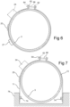
- Fig 6 shows a sensor device where the strap is again a strip 11, but with a different mechanism for tightening the strip.
- the strip has a portion 62 which extends outwards. To tighten the strip, these portions are pulled together by tightening nut 64 on bolt 66. It will be appreciated that between the portions 62 there is a part of the circumference of the vessel 3 which is not in contact with the strip 11. Nevertheless, expansion of the vessel tightens and stretches the strip 11 so that the expansion can be measured by the strain gauge 20.
- Fig 7 shows an arrangement in which the strap of a sensor device has two parts, 71 and 72. Each of these is made from a metal strip and has one end portion bolted at 74 to a rigid supporting structure 76 against which the vessel 3 is lying. The other ends of the two parts 71, 72 have outwardly extending portions 62 which are bolted together with bolt 66 and nut 64 as shown in Fig 6 . Although this two-part strap is not in contact with the whole circumference of the vessel 3, expansion of the vessel 3 will stretch and increase tension in both parts 71, 72 of the strap and thereby stretch the strain gauge 20 adhered to part 71 of the strap.
- Fig 8 shows a further possibility.
- the pressure vessel 3 is lying on and supported by two horizontal rods 82 which are part of a fixed supporting structure.
- the strip 11 is in one piece with end portions 62 pulled together by a nut 64 and bolt 66 as in Fig 6 .
- the strip 11 has sufficient length to pass around the rods 82, and thus secure the vessel 3 to these rods.
- the strain gauge 20 is attached to a part of the strip 11 which is not in direct contact with the vessel 3, but other parts of the strip 11 are in firm contact with the vessel 3 when the bolt and nut 66, 64 are tightened, and so the whole of the strip 11 is subjected to tension if the vessel 3 expands.
- Fig 9 is somewhat similar to Fig 3 but also shows some differences from it. It shows a sensor device similar to that shown in Fig 2 fitted around a lithium ion cell which has a cylindrical outer container 87. Connections to the electrodes within the cell are shown at 88 and 89.
- the temperature sensor 26 shown in Fig 2 is not present.
- a temperature sensor 90 which may be a thermistor, a thermocouple or a temperature measuring integrated circuit, is connected to the electronics package 100 in housing 24 by a flexible lead 91. After the strap has been put in place around the container 87 and tightened into contact with that container, the temperature sensor 90 is fastened to the exterior of the container 87 with adhesive tape 92 (shown broken away in Fig 9 so that the temperature sensor 90 can be seen).
- the electronics package inside housing 24 is also connected to a power supply cable 94. After the strap 11 has been put in place around the container 87, this cable 94 is connected to low voltage DC power supply wiring provided on the structure which holds the batteries.
- the electronics package 100 within the housing 24 communicates wirelessly with a battery management system, such as the system 110 described further below.
- FIG 10 A yet further possibility which is shown by Fig 10 is that the electronics package 100 within housing 24 is connected to a data cable 96. After the strip 11 has been put in place around the container 87, this data cable 96 is connected by a plug and socket connection 97 to a data bus 98 provided on the structure which holds the batteries. Other batteries on the structure are similarly equipped with sensor devices as shown in Fig 10 and are connected in the same way to the data bus 98 which is also connected to the battery management system.
- the data bus is shown schematically as an eight wire data bus 98 and the data cable 96 also has eight wires which connect the electronics package 100 to the data bus 98.
- the microcontroller 106 may communicate with the battery management system 110 over a wired connection. However, if the number of batteries fitted with sensor assemblies as described above is very large, as for a grid scale installation of batteries, individual wired connections would be complex. In some embodiments of sensor apparatus, the electronics package 100 is able to communicate wirelessly with the battery management system 110. The Bluetooth system for short range wireless communication would be suitable for such communication with the battery management system 110 because it has a low power requirement. So, if the electronics package does not have a wired data connection to the battery management system 110, the microcontroller 106 may include a Bluetooth interface or may be connected to a Bluetooth transmitting and receiving module 107 as shown in Fig 11 . Other wireless transmission systems could be used as an alternative to Bluetooth. One such is LoRa and LoRaWAN which define a low power wireless communications system.
- the wireless communication may be arranged to transmit from one electronics package 100 to another which relays the transmission onwards to the battery management system 110.
- the strain gauge 20 and temperature sensors 26, 28 will require some electrical power as will the electronics package 100 in housing 24. In some circumstances this may be provided by a wired connection to a low voltage dc supply. This may be supplied through circuitry 108 which gives a stable dc voltage. However, there may be a preference to avoid adding low voltage wiring to a battery installation, for example, if sensor assemblies embodying the present disclosure are fitted to batteries in an existing installation, or where batteries are to be installed in accordance with an existing installation design. Moreover, for a grid scale installation a number of batteries may be connected in series and in consequence the outer containers of some batteries may be at a significant electrical potential relative to ground, which might make it desirable to avoid any wired connection to a sensor device.
- the electronics package may include or be connected to a small rechargeable battery or a supercapacitor. Providing power wirelessly to charge this may be done using energy harvesting in which a remote transmitter emits radio frequency energy which is then received and harvested by the electronics package 100. This possibility is illustrated by Fig 8 .
- An electrically insulating bracket is fastened to the strip 11. This bracket supports a small aerial 88 which is electrically connected to a rectifier circuit 109 within the electronics package 100.
- the bracket supports a photocell which derives power from ambient light, which may be the artificial lighting of the building in which the battery is installed.
- the electronics package may harvest power using a thermoelectric (Peltier) module which can produce electricity when opposing faces of the module are subject to a temperature differential. Wireless supply of power may also be performed using inductive coupling.
- Fig 12 shows schematically that the battery management system 110 is computer based, having a processor 112, memory 114 and a Bluetooth or other wireless transmitter and receiver 116 for communicating with the electronics packages 100 of the sensor assemblies.
- Fig 13 schematically illustrates a portion of a grid scale installation in which vertically spaced racks 122 support a large number of batteries 123. Portions of three racks 102 are shown in Fig 13 .
- Each battery 123 is fitted with a sensor device 10 of the kind shown in Fig 2 .
- the straps 11 of these assemblies are not visible in Fig 10 but the housings 24 for the electronics packages are seen.
- the sensor assemblies have been fitted so that these electronics packages are close to RFID tags 125 on the racks 122.
- the electronics package 100 of each sensor device includes an RFID reader which is able to read the code held by the closest RFID tag 125 and incorporate this code into communications with the battery management system 110, so that this management system is able to identify the position of the battery for which data is being reported and will be able to continue doing so even if a battery and/or sensor device has to be replaced during maintenance of the installation.
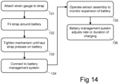
- Fig 14 is a flowchart summarizing the steps of a method or procedure comprising equipping a battery with a sensor device.
- the first stage 131 is to construct a sensor device 10 by attaching a strain gauge 20, an electronics package 100 in housing 24 and temperature sensors 26, 28 to a strip 11 as described above.
- the next stage 132 is to fit the sensor device 10 onto a battery, followed at 133 by using the tightening mechanism to shorten the strap 11 until the strap is taut with at least a length of the strap pressing against the exterior of the battery's outer container.
- Step 134 is to make wired or wireless connection to a battery management system 110.
- the battery management system 110 may adjust the rate or duration of charging of the battery in response to data received from the sensor device.
- Sensor devices embodying this disclosure may be used with any of the various battery types mentioned herein, specifically including nickel hydrogen and alkali metal ion batteries, but may also be used with any battery which undergoes swelling of its outer container during operation or progressively during its working life.
- the various embodiments of this disclosure which have been set out above are intended to assist understanding of this disclosure, but not to limit in any way the scope of this disclosure defined by the following claims.
Landscapes
- Engineering & Computer Science (AREA)
- Chemical & Material Sciences (AREA)
- Chemical Kinetics & Catalysis (AREA)
- Electrochemistry (AREA)
- General Chemical & Material Sciences (AREA)
- Manufacturing & Machinery (AREA)
- Physics & Mathematics (AREA)
- General Physics & Mathematics (AREA)
- Microelectronics & Electronic Packaging (AREA)
- Secondary Cells (AREA)
Applications Claiming Priority (1)
| Application Number | Priority Date | Filing Date | Title |
|---|---|---|---|
| GB2313602.1A GB2633348A (en) | 2023-09-06 | 2023-09-06 | Measuring attachment for batteries |
Publications (2)
| Publication Number | Publication Date |
|---|---|
| EP4521510A2 true EP4521510A2 (fr) | 2025-03-12 |
| EP4521510A3 EP4521510A3 (fr) | 2025-10-15 |
Family
ID=88296854
Family Applications (1)
| Application Number | Title | Priority Date | Filing Date |
|---|---|---|---|
| EP24198723.9A Pending EP4521510A3 (fr) | 2023-09-06 | 2024-09-05 | Accessoire de mesure pour batteries |
Country Status (3)
| Country | Link |
|---|---|
| US (1) | US20250076133A1 (fr) |
| EP (1) | EP4521510A3 (fr) |
| GB (1) | GB2633348A (fr) |
Citations (4)
| Publication number | Priority date | Publication date | Assignee | Title |
|---|---|---|---|---|
| US3669744A (en) | 1971-02-25 | 1972-06-13 | Tsenter Boris I | Hermetically sealed nickel-hydrogen storage cell |
| US3867199A (en) | 1972-06-05 | 1975-02-18 | Communications Satellite Corp | Nickel hydrogen cell |
| US4117206A (en) | 1976-08-17 | 1978-09-26 | Deutsche Automobilgesellschaft Gmbh | Nickel oxide-hydrogen cell |
| US4517264A (en) | 1983-08-24 | 1985-05-14 | Eagle-Picher Industries, Inc. | Lightweight metal-hydrogen cell with improved plate stack supporting means |
Family Cites Families (12)
| Publication number | Priority date | Publication date | Assignee | Title |
|---|---|---|---|---|
| DE602006012940D1 (de) * | 2005-01-20 | 2010-04-29 | Philips Intellectual Property | Anordnung und verfahren zur drucküberwachung in einer batteriezelle |
| CN101107504A (zh) * | 2005-02-18 | 2008-01-16 | 住友重机械工业株式会社 | 应变测量装置及应变测量元件的固定方法 |
| WO2011072295A2 (fr) * | 2009-12-11 | 2011-06-16 | A123 Systems, Inc. | Système et procédé pour estimer un état d'un ensemble batterie |
| CN105339771A (zh) * | 2013-06-06 | 2016-02-17 | 高级传感设计工艺有限责任公司 | 用于压力测量的装置和方法 |
| HUE063455T2 (hu) * | 2018-08-22 | 2024-01-28 | Samsung Sdi Co Ltd | Akkumulátorcellák hõmérsékletének mérése RFID-címkékkel |
| EP3994894B1 (fr) * | 2019-07-02 | 2024-11-13 | Wärtsilä Finland Oy | Détermination d'une configuration d'un bloc-batterie |
| CN110953980B (zh) * | 2019-11-27 | 2022-04-19 | 武汉船用电力推进装置研究所(中国船舶重工集团公司第七一二研究所) | 一种检测深海耐压电池单体鼓胀的方法 |
| US11383616B2 (en) * | 2020-05-01 | 2022-07-12 | Nissan North America, Inc. | Vehicle battery life tracking system |
| CN216246926U (zh) * | 2021-11-26 | 2022-04-08 | 郑州大学 | 一种固定索力计的箍紧装置 |
| CN218781926U (zh) * | 2022-12-12 | 2023-03-31 | 阳光储能技术有限公司 | 一种电芯间的压应力检测装置及检测系统 |
| CN116154380A (zh) * | 2022-12-30 | 2023-05-23 | 埃斯倍风电科技(青岛)有限公司 | 一种电池模组 |
| CN116198768A (zh) * | 2023-02-24 | 2023-06-02 | 合肥国轩高科动力能源有限公司 | 一种自适应调节的动力电池模组打包组件及其动力电池模组 |
-
2023
- 2023-09-06 GB GB2313602.1A patent/GB2633348A/en active Pending
-
2024
- 2024-09-05 EP EP24198723.9A patent/EP4521510A3/fr active Pending
- 2024-09-05 US US18/824,944 patent/US20250076133A1/en active Pending
Patent Citations (4)
| Publication number | Priority date | Publication date | Assignee | Title |
|---|---|---|---|---|
| US3669744A (en) | 1971-02-25 | 1972-06-13 | Tsenter Boris I | Hermetically sealed nickel-hydrogen storage cell |
| US3867199A (en) | 1972-06-05 | 1975-02-18 | Communications Satellite Corp | Nickel hydrogen cell |
| US4117206A (en) | 1976-08-17 | 1978-09-26 | Deutsche Automobilgesellschaft Gmbh | Nickel oxide-hydrogen cell |
| US4517264A (en) | 1983-08-24 | 1985-05-14 | Eagle-Picher Industries, Inc. | Lightweight metal-hydrogen cell with improved plate stack supporting means |
Non-Patent Citations (2)
| Title |
|---|
| CHEN ET AL.: "Nickel-hydrogen batteries for large-scale energy storage", PNAS, vol. 15, 2018, pages 11694 - 11699, XP055969678, DOI: 10.1073/pnas.1809344115 |
| MICHELINI ET AL.: "Experimental Investigation on Reversible Swelling Mechanisms of Lithium-Ion Batteries under a Varying Preload Force", BATTERIES, vol. 9, 2023, pages 218 |
Also Published As
| Publication number | Publication date |
|---|---|
| EP4521510A3 (fr) | 2025-10-15 |
| US20250076133A1 (en) | 2025-03-06 |
| GB202313602D0 (en) | 2023-10-18 |
| GB2633348A (en) | 2025-03-12 |
Similar Documents
| Publication | Publication Date | Title |
|---|---|---|
| EP1856760B1 (fr) | Dispositif et méthode pour surveiller la pression dans une batterie | |
| CN113471555B (zh) | 智能电芯、电池系统以及电动汽车 | |
| US4689544A (en) | Control of the charging of pressurized gas-metal electrical storage cells | |
| CN217719732U (zh) | 一种电池安全监测装置及电池 | |
| CA2483404C (fr) | Surveillant un parametre a faible consommation d'electricite pour enregistreur chronologique des donnees du train d'atterrissage d'un aeronef | |
| US7244527B2 (en) | Multi-cell battery charge control | |
| CN216903092U (zh) | 电池包结构 | |
| EP2524412A1 (fr) | Procédés et systèmes de mesure d'un état de charge | |
| CN217934009U (zh) | 顶盖组件、电池单体、电池及用电装置 | |
| CN114914516A (zh) | 电芯内部集成柔性压力监测传感器的锂电池 | |
| US20250076133A1 (en) | Measuring attachment for batteries | |
| CN201812902U (zh) | 一种内压自检电池 | |
| CN212721859U (zh) | 无线拉力传感器和具有其的无线传感器监测系统 | |
| CN115911620A (zh) | 电池监测装置及电池装置 | |
| CN206235424U (zh) | 用于监测电池充放电鼓胀压力的测试装置 | |
| EP4521060A1 (fr) | Ensemble de détection de déformation, batterie et dispositif électrique | |
| CN209802563U (zh) | 埋入式压力传感器 | |
| EP0649520B1 (fr) | Appareil de mesure de la pression a l'interieur d'une cellule electrochimique rechargeable | |
| JP7517215B2 (ja) | 温度測定方法、温度測定装置、及び電池システム | |
| CN219497887U (zh) | 电池包 | |
| CN220652096U (zh) | 一种温度采集模组及电池 | |
| KR20210081611A (ko) | 배터리 셀의 스웰링 특성 분석용 파우치 및 이를 이용한 배터리 셀의 스웰링 특성 분석 방법 | |
| CN206038870U (zh) | 一种配合至生产线的自动化锂电池检测装置 | |
| CN223612470U (zh) | 电池装置以及用电设备 | |
| CN217306592U (zh) | 电池结构 |
Legal Events
| Date | Code | Title | Description |
|---|---|---|---|
| PUAI | Public reference made under article 153(3) epc to a published international application that has entered the european phase |
Free format text: ORIGINAL CODE: 0009012 |
|
| STAA | Information on the status of an ep patent application or granted ep patent |
Free format text: STATUS: THE APPLICATION HAS BEEN PUBLISHED |
|
| AK | Designated contracting states |
Kind code of ref document: A2 Designated state(s): AL AT BE BG CH CY CZ DE DK EE ES FI FR GB GR HR HU IE IS IT LI LT LU LV MC ME MK MT NL NO PL PT RO RS SE SI SK SM TR |
|
| RIC1 | Information provided on ipc code assigned before grant |
Ipc: H01M 50/569 20210101ALI20250514BHEP Ipc: H01M 50/256 20210101ALI20250514BHEP Ipc: H01M 50/119 20210101ALI20250514BHEP Ipc: H01M 10/44 20060101ALI20250514BHEP Ipc: G01L 5/00 20060101ALI20250514BHEP Ipc: G01B 21/02 20060101ALI20250514BHEP Ipc: H01M 10/48 20060101ALI20250514BHEP Ipc: H01M 10/42 20060101AFI20250514BHEP |
|
| PUAL | Search report despatched |
Free format text: ORIGINAL CODE: 0009013 |
|
| AK | Designated contracting states |
Kind code of ref document: A3 Designated state(s): AL AT BE BG CH CY CZ DE DK EE ES FI FR GB GR HR HU IE IS IT LI LT LU LV MC ME MK MT NL NO PL PT RO RS SE SI SK SM TR |
|
| RIC1 | Information provided on ipc code assigned before grant |
Ipc: H01M 10/42 20060101AFI20250905BHEP Ipc: H01M 10/48 20060101ALI20250905BHEP Ipc: G01B 21/02 20060101ALI20250905BHEP Ipc: G01L 5/00 20060101ALI20250905BHEP Ipc: H01M 10/44 20060101ALI20250905BHEP Ipc: H01M 50/119 20210101ALI20250905BHEP Ipc: H01M 50/256 20210101ALI20250905BHEP Ipc: H01M 50/569 20210101ALI20250905BHEP Ipc: H01M 50/107 20210101ALI20250905BHEP |