EP4521596A1 - Verfahren zur steuerung der stromversorgung und elektronische vorrichtung damit - Google Patents
Verfahren zur steuerung der stromversorgung und elektronische vorrichtung damit Download PDFInfo
- Publication number
- EP4521596A1 EP4521596A1 EP23827336.1A EP23827336A EP4521596A1 EP 4521596 A1 EP4521596 A1 EP 4521596A1 EP 23827336 A EP23827336 A EP 23827336A EP 4521596 A1 EP4521596 A1 EP 4521596A1
- Authority
- EP
- European Patent Office
- Prior art keywords
- power
- magnitude
- electronic device
- power source
- charging circuit
- Prior art date
- Legal status (The legal status is an assumption and is not a legal conclusion. Google has not performed a legal analysis and makes no representation as to the accuracy of the status listed.)
- Pending
Links
Images



Classifications
-
- H—ELECTRICITY
- H02—GENERATION; CONVERSION OR DISTRIBUTION OF ELECTRIC POWER
- H02J—ELECTRIC POWER NETWORKS; CIRCUIT ARRANGEMENTS OR SYSTEMS FOR SUPPLYING OR DISTRIBUTING ELECTRIC POWER; SYSTEMS FOR STORING ELECTRIC ENERGY
- H02J7/00—Circuit arrangements for charging or discharging batteries or for supplying loads from batteries
- H02J7/865—Battery or charger load switching, e.g. concurrent charging and load supply
-
- G—PHYSICS
- G06—COMPUTING OR CALCULATING; COUNTING
- G06F—ELECTRIC DIGITAL DATA PROCESSING
- G06F1/00—Details not covered by groups G06F3/00 - G06F13/00 and G06F21/00
- G06F1/26—Power supply means, e.g. regulation thereof
-
- G—PHYSICS
- G06—COMPUTING OR CALCULATING; COUNTING
- G06F—ELECTRIC DIGITAL DATA PROCESSING
- G06F1/00—Details not covered by groups G06F3/00 - G06F13/00 and G06F21/00
- G06F1/26—Power supply means, e.g. regulation thereof
- G06F1/263—Arrangements for using multiple switchable power supplies, e.g. battery and AC
-
- H—ELECTRICITY
- H02—GENERATION; CONVERSION OR DISTRIBUTION OF ELECTRIC POWER
- H02J—ELECTRIC POWER NETWORKS; CIRCUIT ARRANGEMENTS OR SYSTEMS FOR SUPPLYING OR DISTRIBUTING ELECTRIC POWER; SYSTEMS FOR STORING ELECTRIC ENERGY
- H02J2207/00—Details of circuit arrangements for charging or discharging batteries or supplying loads from batteries
- H02J2207/30—Charge provided using DC bus or data bus of a computer
-
- H—ELECTRICITY
- H02—GENERATION; CONVERSION OR DISTRIBUTION OF ELECTRIC POWER
- H02J—ELECTRIC POWER NETWORKS; CIRCUIT ARRANGEMENTS OR SYSTEMS FOR SUPPLYING OR DISTRIBUTING ELECTRIC POWER; SYSTEMS FOR STORING ELECTRIC ENERGY
- H02J2207/00—Details of circuit arrangements for charging or discharging batteries or supplying loads from batteries
- H02J2207/40—Details of circuit arrangements for charging or discharging batteries or supplying loads from batteries adapted for charging from various sources, e.g. AC, DC or multivoltage
-
- H—ELECTRICITY
- H02—GENERATION; CONVERSION OR DISTRIBUTION OF ELECTRIC POWER
- H02J—ELECTRIC POWER NETWORKS; CIRCUIT ARRANGEMENTS OR SYSTEMS FOR SUPPLYING OR DISTRIBUTING ELECTRIC POWER; SYSTEMS FOR STORING ELECTRIC ENERGY
- H02J7/00—Circuit arrangements for charging or discharging batteries or for supplying loads from batteries
- H02J7/40—Circuit arrangements for charging or discharging batteries or for supplying loads from batteries characterised by the exchange of charge or discharge related data
- H02J7/42—Circuit arrangements for charging or discharging batteries or for supplying loads from batteries characterised by the exchange of charge or discharge related data with electronic devices having internal batteries, e.g. mobile phones
-
- H—ELECTRICITY
- H02—GENERATION; CONVERSION OR DISTRIBUTION OF ELECTRIC POWER
- H02J—ELECTRIC POWER NETWORKS; CIRCUIT ARRANGEMENTS OR SYSTEMS FOR SUPPLYING OR DISTRIBUTING ELECTRIC POWER; SYSTEMS FOR STORING ELECTRIC ENERGY
- H02J7/00—Circuit arrangements for charging or discharging batteries or for supplying loads from batteries
- H02J7/60—Circuit arrangements for charging or discharging batteries or for supplying loads from batteries including safety or protection arrangements
- H02J7/68—Circuit arrangements for charging or discharging batteries or for supplying loads from batteries including safety or protection arrangements using circuits for correcting or protecting against reverse-polarity
-
- H—ELECTRICITY
- H02—GENERATION; CONVERSION OR DISTRIBUTION OF ELECTRIC POWER
- H02J—ELECTRIC POWER NETWORKS; CIRCUIT ARRANGEMENTS OR SYSTEMS FOR SUPPLYING OR DISTRIBUTING ELECTRIC POWER; SYSTEMS FOR STORING ELECTRIC ENERGY
- H02J7/00—Circuit arrangements for charging or discharging batteries or for supplying loads from batteries
- H02J7/855—Circuit arrangements for charging or discharging batteries or for supplying loads from batteries with circuits adapted for supplying loads from the battery
Definitions
- Various embodiments of the present disclosure relate to an electronic device that supports connection to an external electronic device and an operation method thereof, specifically, regarding an electronic device that is supplied with power through a universal serial bus (USB) port and an operation method thereof, to a method of configuring an electronic device that is capable of simultaneously being supplied with one or more power in the electronic device that is supplied with power through one or more USB ports.
- USB universal serial bus
- USB universal serial bus
- USB The universal serial bus
- PD power delivery
- PD power delivery
- the external power supply device may supply power required to drive the electronic device through a USB connector.
- a power supply device that is connected to an electronic device using the USB Type-C specification may transmit or receive control signals to or from the electronic device through a configuration channel (CC) defined in the USB Type-C specification.
- the electronic device connected to the power supply device may transmit or receive control signals to or from the external power supply device through the configuration channel (CC) defined in the USB Type-C specification.
- An electronic device that includes multiple USB-C ports may be supplied with power from any USB-C port. However, the electronic device may be supplied with power by selecting only one port (selecting higher power among multiple power sources) even if multiple power sources are simultaneously connected.
- the electronic device may select only one port to be supplied with power when two power sources of 45W and 65W are connected to two ports, respectively. Therefore, even if the electronic device is designed to use 110W, which is the sum of two power sources, there may be a limitation that only one power source is available to be used due to the structure of the port.
- the electronic device when the electronic device selects multiple ports to be supplied with power, the electronic device may have the limitation of including multiple charging circuits.
- An electronic device that includes multiple charging circuits may have limitations in practical implementation due to controlling different values of power.
- the electronic device may include a first port connected to a first power source capable of supplying power to the electronic device, a second port connected to a second power source capable of supplying power to the electronic device, a charging circuit electrically connected to the first and second ports and configured to receive power supplied through the first port and/or the second port, a first switch configured to control an electric connection between the charging circuit and the first port, a second switch configured to control an electric connection between the charging circuit and the second port, and a processor electrically connected to the charging circuit.
- the processor may acquire information indicating the magnitude of first power supplied from the first power source and information indicating the magnitude of second power supplied from the second power source, compare the magnitude of first power supplied from the first power source and the magnitude of second power supplied from the second power source, compare the magnitude of the second power and the magnitude of the sum of multiple power values when the magnitude of power supplied from the second power source is changed to be equal to the magnitude of the first power on the basis of determining that the magnitude of the first power is relatively smaller than the magnitude of the second power, control the magnitude of power supplied from the second power source to be equal to the magnitude of the first power in response to identifying that the magnitude of the second power is relatively smaller compared with the magnitude of the sum of multiple power values, and control the first and second switches so as to supply power to the charging circuit using both the first and second power sources.
- the method may include acquiring information indicating magnitude of first power supplied from a first power source and information indicating magnitude of second power supplied from a second power source, comparing the magnitude of the first power supplied from the first power source and the magnitude of the second power supplied from the second power source, comparing the magnitude of the second power and the magnitude of a sum of multiple power values when the magnitude of power supplied from the second power source is changed to be equal to the magnitude of the first power on the basis of determining that the magnitude of the first power is relatively smaller than the magnitude of the second power, controlling the magnitude of power supplied from the second power source to be equal to the magnitude of the first power in response to identifying that the magnitude of the second power is relatively smaller compared with the magnitude of the sum of multiple power values, and controlling the first and second switches so as to supply power to a charging circuit using both the first and second power sources.
- the electronic device can reduce charging time by using the power of multiple power sources simultaneously in a situation where multiple power sources are connected to multiple ports.
- the electronic device can include only one charging circuit, reducing costs and reducing installation space.
- the electronic device can reduce configuration complexity compared to cases using multiple charging circuits, as the electronic device uses only one charging circuit.
- Fig. 1 is a block diagram illustrating an electronic device 101 in a network environment 100 according to various embodiments.
- the electronic device 101 in the network environment 100 may communicate with an electronic device 102 via a first network 198 (e.g., a short-range wireless communication network), or at least one of an electronic device 104 or a server 108 via a second network 199 (e.g., a long-range wireless communication network).
- the electronic device 101 may communicate with the electronic device 104 via the server 108.
- the electronic device 101 may include a processor 120, memory 130, an input module 150, a sound output module 155, a display module 160, an audio module 170, a sensor module 176, an interface 177, a connecting terminal 178, a haptic module 179, a camera module 180, a power management module 188, a battery 189, a communication module 190, a subscriber identification module(SIM) 196, or an antenna module 197.
- at least one of the components e.g., the connecting terminal 178) may be omitted from the electronic device 101, or one or more other components may be added in the electronic device 101.
- some of the components e.g., the sensor module 176, the camera module 180, or the antenna module 197) may be implemented as a single component (e.g., the display module 160).
- the processor 120 may execute, for example, software (e.g., a program 140) to control at least one other component (e.g., a hardware or software component) of the electronic device 101 coupled with the processor 120, and may perform various data processing or computation. According to one embodiment, as at least part of the data processing or computation, the processor 120 may store a command or data received from another component (e.g., the sensor module 176 or the communication module 190) in volatile memory 132, process the command or the data stored in the volatile memory 132, and store resulting data in non-volatile memory 134.
- software e.g., a program 140
- the processor 120 may store a command or data received from another component (e.g., the sensor module 176 or the communication module 190) in volatile memory 132, process the command or the data stored in the volatile memory 132, and store resulting data in non-volatile memory 134.
- the processor 120 may include a main processor 121 (e.g., a central processing unit (CPU) or an application processor (AP)), or an auxiliary processor 123 (e.g., a graphics processing unit (GPU), a neural processing unit (NPU), an image signal processor (ISP), a sensor hub processor, or a communication processor (CP)) that is operable independently from, or in conjunction with, the main processor 121.
- a main processor 121 e.g., a central processing unit (CPU) or an application processor (AP)
- auxiliary processor 123 e.g., a graphics processing unit (GPU), a neural processing unit (NPU), an image signal processor (ISP), a sensor hub processor, or a communication processor (CP)
- the main processor 121 may be adapted to consume less power than the main processor 121, or to be specific to a specified function.
- the auxiliary processor 123 may be implemented as separate from, or as part of the main processor 121.
- the auxiliary processor 123 may control at least some of functions or states related to at least one component (e.g., the display module 160, the sensor module 176, or the communication module 190) among the components of the electronic device 101, instead of the main processor 121 while the main processor 121 is in an inactive (e.g., sleep) state, or together with the main processor 121 while the main processor 121 is in an active state (e.g., executing an application).
- the auxiliary processor 123 e.g., an image signal processor or a communication processor
- the auxiliary processor 123 may include a hardware structure specified for artificial intelligence model processing.
- An artificial intelligence model may be generated by machine learning. Such learning may be performed, e.g., by the electronic device 101 where the artificial intelligence is performed or via a separate server (e.g., the server 108). Learning algorithms may include, but are not limited to, e.g., supervised learning, unsupervised learning, semi-supervised learning, or reinforcement learning.
- the artificial intelligence model may include a plurality of artificial neural network layers.
- the artificial neural network may be a deep neural network (DNN), a convolutional neural network (CNN), a recurrent neural network (RNN), a restricted boltzmann machine (RBM), a deep belief network (DBN), a bidirectional recurrent deep neural network (BRDNN), deep Q-network or a combination of two or more thereof but is not limited thereto.
- the artificial intelligence model may, additionally or alternatively, include a software structure other than the hardware structure.
- the memory 130 may store various data used by at least one component (e.g., the processor 120 or the sensor module 176) of the electronic device 101.
- the various data may include, for example, software (e.g., the program 140) and input data or output data for a command related thererto.
- the memory 130 may include the volatile memory 132 or the non-volatile memory 134.
- the program 140 may be stored in the memory 130 as software, and may include, for example, an operating system (OS) 142, middleware 144, or an application 146.
- OS operating system
- middleware middleware
- application application
- the input module 150 may receive a command or data to be used by another component (e.g., the processor 120) of the electronic device 101, from the outside (e.g., a user) of the electronic device 101.
- the input module 150 may include, for example, a microphone, a mouse, a keyboard, a key (e.g., a button), or a digital pen (e.g., a stylus pen).
- the sound output module 155 may output sound signals to the outside of the electronic device 101.
- the sound output module 155 may include, for example, a speaker or a receiver.
- the speaker may be used for general purposes, such as playing multimedia or playing record.
- the receiver may be used for receiving incoming calls. According to an embodiment, the receiver may be implemented as separate from, or as part of the speaker.
- the display module 160 may visually provide information to the outside (e.g., a user) of the electronic device 101.
- the display module 160 may include, for example, a display, a hologram device, or a projector and control circuitry to control a corresponding one of the display, hologram device, and projector.
- the display module 160 may include a touch sensor adapted to detect a touch, or a pressure sensor adapted to measure the intensity of force incurred by the touch.
- the audio module 170 may convert a sound into an electrical signal and vice versa. According to an embodiment, the audio module 170 may obtain the sound via the input module 150, or output the sound via the sound output module 155 or a headphone of an external electronic device (e.g., an electronic device 102) directly (e.g., wiredly) or wirelessly coupled with the electronic device 101.
- an external electronic device e.g., an electronic device 102
- directly e.g., wiredly
- wirelessly e.g., wirelessly
- the sensor module 176 may detect an operational state (e.g., power or temperature) of the electronic device 101 or an environmental state (e.g., a state of a user) external to the electronic device 101, and then generate an electrical signal or data value corresponding to the detected state.
- the sensor module 176 may include, for example, a gesture sensor, a gyro sensor, an atmospheric pressure sensor, a magnetic sensor, an acceleration sensor, a grip sensor, a proximity sensor, a color sensor, an infrared (IR) sensor, a biometric sensor, a temperature sensor, a humidity sensor, or an illuminance sensor.
- the interface 177 may support one or more specified protocols to be used for the electronic device 101 to be coupled with the external electronic device (e.g., the electronic device 102) directly (e.g., wiredly) or wirelessly.
- the interface 177 may include, for example, a high definition multimedia interface (HDMI), a universal serial bus (USB) interface, a secure digital (SD) card interface, or an audio interface.
- HDMI high definition multimedia interface
- USB universal serial bus
- SD secure digital
- a connecting terminal 178 may include a connector via which the electronic device 101 may be physically connected with the external electronic device (e.g., the electronic device 102).
- the connecting terminal 178 may include, for example, a HDMI connector, a USB connector, a SD card connector, or an audio connector (e.g., a headphone connector).
- the haptic module 179 may convert an electrical signal into a mechanical stimulus (e.g., a vibration or a movement) or electrical stimulus which may be recognized by a user via his tactile sensation or kinesthetic sensation.
- the haptic module 179 may include, for example, a motor, a piezoelectric element, or an electric stimulator.
- the camera module 180 may capture a still image or moving images.
- the camera module 180 may include one or more lenses, image sensors, image signal processors, or flashes.
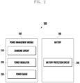
- the power management module 188 may manage power supplied to the electronic device 101.
- the power management module 188 may be implemented as at least part of, for example, a power management integrated circuit (PMIC).
- PMIC power management integrated circuit
- the battery 189 may supply power to at least one component of the electronic device 101.
- the battery 189 may include, for example, a primary cell which is not rechargeable, a secondary cell which is rechargeable, or a fuel cell.
- the communication module 190 may support establishing a direct (e.g., wired) communication channel or a wireless communication channel between the electronic device 101 and the external electronic device (e.g., the electronic device 102, the electronic device 104, or the server 108) and performing communication via the established communication channel.
- the communication module 190 may include one or more communication processors that are operable independently from the processor 120 (e.g., the application processor (AP)) and supports a direct (e.g., wired) communication or a wireless communication.
- AP application processor
- the communication module 190 may include a wireless communication module 192 (e.g., a cellular communication module, a short-range wireless communication module, or a global navigation satellite system (GNSS) communication module) or a wired communication module 194 (e.g., a local area network (LAN) communication module or a power line communication (PLC) module).
- a wireless communication module 192 e.g., a cellular communication module, a short-range wireless communication module, or a global navigation satellite system (GNSS) communication module
- GNSS global navigation satellite system
- wired communication module 194 e.g., a local area network (LAN) communication module or a power line communication (PLC) module.
- LAN local area network
- PLC power line communication
- a corresponding one of these communication modules may communicate with the external electronic device via the first network 198 (e.g., a short-range communication network, such as BluetoothTM, wireless-fidelity (Wi-Fi) direct, or infrared data association (IrDA)) or the second network 199 (e.g., a long-range communication network, such as a legacy cellular network, a 5G network, a next-generation communication network, the Internet, or a computer network (e.g., LAN or wide area network (WAN)).
- first network 198 e.g., a short-range communication network, such as BluetoothTM, wireless-fidelity (Wi-Fi) direct, or infrared data association (IrDA)
- the second network 199 e.g., a long-range communication network, such as a legacy cellular network, a 5G network, a next-generation communication network, the Internet, or a computer network (e.g., LAN or wide area network (WAN)).
- the wireless communication module 192 may identify and authenticate the electronic device 101 in a communication network, such as the first network 198 or the second network 199, using subscriber information (e.g., international mobile subscriber identity (IMSI)) stored in the subscriber identification module 196.
- subscriber information e.g., international mobile subscriber identity (IMSI)
- the wireless communication module 192 may support a 5G network, after a 4G network, and next-generation communication technology, e.g., new radio (NR) access technology.
- the NR access technology may support enhanced mobile broadband (eMBB), massive machine type communications (mMTC), or ultra-reliable and low-latency communications (URLLC).
- eMBB enhanced mobile broadband
- mMTC massive machine type communications
- URLLC ultra-reliable and low-latency communications
- the wireless communication module 192 may support a high-frequency band (e.g., the mmWave band) to achieve, e.g., a high data transmission rate.
- the wireless communication module 192 may support various technologies for securing performance on a high-frequency band, such as, e.g., beamforming, massive multiple-input and multiple-output (massive MIMO), full dimensional MIMO (FD-MIMO), array antenna, analog beam-forming, or large scale antenna.
- the wireless communication module 192 may support various requirements specified in the electronic device 101, an external electronic device (e.g., the electronic device 104), or a network system (e.g., the second network 199).
- the wireless communication module 192 may support a peak data rate (e.g., 20Gbps or more) for implementing eMBB, loss coverage (e.g., 164dB or less) for implementing mMTC, or U-plane latency (e.g., 0.5ms or less for each of downlink (DL) and uplink (UL), or a round trip of 1ms or less) for implementing URLLC.
- a peak data rate e.g., 20Gbps or more
- loss coverage e.g., 164dB or less
- U-plane latency e.g., 0.5ms or less for each of downlink (DL) and uplink (UL), or a round trip of 1ms or less
- the antenna module 197 may transmit or receive a signal or power to or from the outside (e.g., the external electronic device) of the electronic device 101.
- the antenna module 197 may include an antenna including a radiating element composed of a conductive material or a conductive pattern formed in or on a substrate (e.g., a printed circuit board (PCB)).
- the antenna module 197 may include a plurality of antennas (e.g., array antennas). In such a case, at least one antenna appropriate for a communication scheme used in the communication network, such as the first network 198 or the second network 199, may be selected, for example, by the communication module 190 (e.g., the wireless communication module 192) from the plurality of antennas.
- the signal or the power may then be transmitted or received between the communication module 190 and the external electronic device via the selected at least one antenna.
- another component e.g., a radio frequency integrated circuit (RFIC)
- RFIC radio frequency integrated circuit
- the antenna module 197 may form a mmWave antenna module.
- the mmWave antenna module may include a printed circuit board, a RFIC disposed on a first surface (e.g., the bottom surface) of the printed circuit board, or adjacent to the first surface and capable of supporting a designated high-frequency band (e.g., the mmWave band), and a plurality of antennas (e.g., array antennas) disposed on a second surface (e.g., the top or a side surface) of the printed circuit board, or adjacent to the second surface and capable of transmitting or receiving signals of the designated high-frequency band.
- a RFIC disposed on a first surface (e.g., the bottom surface) of the printed circuit board, or adjacent to the first surface and capable of supporting a designated high-frequency band (e.g., the mmWave band)
- a plurality of antennas e.g., array antennas
- At least some of the above-described components may be coupled mutually and communicate signals (e.g., commands or data) therebetween via an inter-peripheral communication scheme (e.g., a bus, general purpose input and output (GPIO), serial peripheral interface (SPI), or mobile industry processor interface (MIPI)).
- an inter-peripheral communication scheme e.g., a bus, general purpose input and output (GPIO), serial peripheral interface (SPI), or mobile industry processor interface (MIPI)
- commands or data may be transmitted or received between the electronic device 101 and the external electronic device 104 via the server 108 coupled with the second network 199.
- Each of the electronic devices 102 or 104 may be a device of a same type as, or a different type, from the electronic device 101.
- all or some of operations to be executed at the electronic device 101 may be executed at one or more of the external electronic devices 102, 104, or 108. For example, if the electronic device 101 should perform a function or a service automatically, or in response to a request from a user or another device, the electronic device 101, instead of, or in addition to, executing the function or the service, may request the one or more external electronic devices to perform at least part of the function or the service.
- a method may be included and provided in a computer program product.
- the computer program product may be traded as a product between a seller and a buyer.
- the computer program product may be distributed in the form of a machine-readable storage medium (e.g., compact disc read only memory (CD-ROM)), or be distributed (e.g., downloaded or uploaded) online via an application store (e.g., PlayStoreTM), or between two user devices (e.g., smart phones) directly. If distributed online, at least part of the computer program product may be temporarily generated or at least temporarily stored in the machine-readable storage medium, such as memory of the manufacturer's server, a server of the application store, or a relay server.
- CD-ROM compact disc read only memory
- an application store e.g., PlayStoreTM
- two user devices e.g., smart phones
- FIG. 3 briefly illustrates configurations required in the electronic device in FIGS. 1 and 2 for describing the present invention, although other configurations may be included in addition to those illustrated, and some configurations may be omitted.
- the electronic device e.g., electronic device 101 in FIG. 1
- the electronic device may include a system 330 that includes a first port 310 (e.g., connection terminal 178 in FIG. 1 ), a second port 312, an interface power management IC (IF PMIC) 320 (e.g., power management module 188 in FIG. 1 ), a battery 350 (e.g., battery 189 in FIG. 1 ), and a processor 340.
- IF PMIC interface power management IC
- the electronic device 400 may perform a function of protecting a circuit from reverse current (reverse current protection function) using at least one switch.
- the processor 430 may acquire information indicating at least one voltage and current that may be output by the power source connected using the PD controller 420.
- the processor 430 may determine whether at least one switch operates on the basis of the acquired information.
- the operation of at least one switch may refer to generating an electrical connection between the power source and the electronic device 400 so that the connected power source supplies power to the electronic device 400.
- the non-operation of at least one switch may refer to cutting off an electrical connection between the power source and the electronic device 400 so that the connected power source does not supply power to the electronic device 400.
- the electronic device 400 may further include a power delivery integrated circuit (PDIC).
- PDIC power delivery integrated circuit
- the electronic device 400 may establish a communication connection with at least one of the first power source or the second power source connected to the electronic device using the PDIC and may receive information including the type or charging capacity of the first power source or the second power source.
- the electronic device 400 may distribute power to the processor 430 and the charging circuit 440 using a power management integrated circuit (PMIC).
- PMIC power management integrated circuit
- the electronic device 400 may acquire information indicating the power of connected power sources using the processor 430 in a situation where multiple power sources with different power are connected.
- case 1 in Table 1 may refer to a situation where the electronic device 400 has a power source of 45 W (15 V/3 A) connected to the first port 410 and a power source of 65 W (20 V/3.25 A) connected to the second port 412.
- the electronic device 400 may acquire information indicating power of a connected power source using the processor 430.
- the electronic device 400 may cut off the connection of at least one of the connected multiple power sources on the basis of the internal temperature rising above a predetermined level. For example, in case 1, the electronic device 400 may cut off the connection with the power source indicating 45 W on the basis of the temperature of the processor 430 rising above a predetermined level. The electronic device 400 may supply power to the charging circuit 440 using only the power source indicating 65 W.
- the electronic device 400 may cut off the connection with the power source indicating 65 W on the basis of the temperature of the processor 430 rising above a predetermined level.
- the electronic device 400 may supply power to the charging circuit 440 using only the power source indicating 45 W.
- the electronic device 400 may limit the current input to the charging circuit 440 using the processor 430 when the sum of the power of input power sources exceeds maximum allowable capacity of the system.
- the PD controller 420 may maintain the voltage supplied to the charging circuit 440 constant and control the current supplied to the charging circuit 440 so that the current does not exceed a predetermined level.
- the electronic device in a situation where a 45 W (15 V/3 A) power source is connected to the first port 410 and a 65 W (20 V/3.25 A) power source is connected to the second port 412, the electronic device has a limitation in that only one power source may be used due to a difference in voltage between the power sources connected to both ports.
- the electronic device according to the comparative embodiment may have difficulty fully utilizing the power, even in a situation where the connected multiple power sources have a total power of 110 W and the battery is capable of being supplied with a power of 110W, due to the connection structure of the multiple power sources connected to the ports.
- the electronic device may need to include multiple charging circuits to use multiple power sources with different voltages in a situation where a 45W (15V/3A) power source is connected to the first port 410 and a 65W (20V/3.25A) power source is connected to the second port 412.
- the electronic device may include multiple charging circuits, which may increase the installation space and lead to increased costs.
- the electronic device by including multiple charging circuits, may consume relatively more system resources to control multiple charging circuits compared to one charging circuit.
- the electronic device 400 may supply relatively greater power to charge the battery 450 using multiple power sources with different voltages, while using only one charging circuit 440.
- the electronic device 400 may prevent current from flowing in the reverse direction by using multiple switches while using multiple power sources.
- FIG. 5 illustrates a flowchart of a method of controlling power supply of an electronic device, according to various embodiments.
- FIG. 5 may be implemented on the basis of instructions that may be stored in a computer recording medium or memory (e.g., memory 130 in FIG. 1 ).
- An illustrated method 500 may be executed by the electronic device (e.g., electronic device 400 in FIG. 4 ) described above through FIGS. 1 to 4 , the technical features of which have been described above will be omitted hereinafter.
- the electronic device 400 may acquire information indicating the power, voltage, and current of the power sources connected to each port under the control of the processor (e.g., processor 340 in FIG. 3 ). For example, the electronic device 400 may acquire information indicating that the power source connected to the first port (e.g., first port 410 in FIG. 4 ) has 45 W (15 V, 3 A) and that the power source connected to the second port (e.g., second port 412 in FIG. 4 ) has 65 W (20 V, 3.5 A).
- the number of ports and power sources included in the electronic device 400 is not limited to the embodiment of operation 510.
- the electronic device 400 may identify whether the power supplied from multiple power sources is equal on the basis of acquiring information indicating the power of power source.
- the electronic device 400 may supply power to the charging circuit (e.g., charging circuit 440 in FIG. 4 ) using all power sources connected to each port, on the basis of the power supplied from multiple power sources being equal.
- the electronic device 400 may convert the magnitudes of both power sources to have the same current and voltage when the power of both power sources is equal, but the current and voltage differ.
- the electronic device 400 may compare the sum of the power of the converted power sources with the value of the power before conversion to determine whether to use all multiple power sources or one power source.
- the electronic device 400 may determine whether to supply power using all multiple power sources or to supply power using only one power source with the maximum power, on the basis of the power supplied from the multiple power sources not being equal.
- the electronic device 400 may acquire information indicating the power of the power sources connected to each port using the processor 430 in a situation where two power sources are connected to the electronic device 400 through each port.
- the electronic device 400 may compare the magnitude of first power supplied from the first power source with the magnitude of second power supplied from the second power source.
- the electronic device 400 may adjust multiple power sources (e.g., first power source or second power source) to have the same power magnitude as the first power (current and voltage) on the basis of determining that the magnitude of the first power is relatively smaller than the magnitude of the second power.
- the electronic device 400 may be supplied with power to the charging circuit 440 using all multiple power sources when the sum of the adjusted multiple power values is greater than the power of the second power source, which has the greatest value.
- the electronic device 400 may change the power of power sources connected to each port to be the same as the value (current and voltage) indicating the power of the first power source and supply power to the charging circuit 440 using multiple power sources.
- the electronic device 400 may operate both the first switch (e.g., first switch 410-1 in FIG. 4 ) and the second switch (e.g., second switch 412-1 in FIG. 4 ) to supply power to the charging circuit 440 using both the first power source and the second power source.
- the first switch 410-1 may be positioned between the charging circuit 440 and the first port (e.g., first port 410 in FIG. 4 ) to control an electrical connection
- the second switch 412-1 may be positioned between the charging circuit 440 and the second port (e.g., second port 412 in FIG. 4 ) to control an electrical connection.
- the power source connected to the first port 410 may supply power with a magnitude of 45 W (15 V/3 A), and the power source connected to the second port 412 may supply power with a magnitude of 65W (20 V/3.25 A).
- the electronic device 400 may change the power to 45 W (15 V/3 A) so that the current and voltage of the connected power sources are equal, and supply power to the charging circuit 440 using multiple power sources.
- the total power supplied may have a magnitude of 90 W (15 V/6 A).
- the electronic device 400 may determine that a relatively greater amount of power may be supplied when supplying power to the charging circuit 440 using multiple power sources, compared with supplying power to the charging circuit 440 using one power source.
- the electronic device 400 may change the magnitude of the power supplied from the connected power sources to 45 W (15 V/3 A) in order to use multiple power sources.
- the electronic device 400 may supply 90 W (15 V/6 A) of power to the charging circuit 440 using multiple power sources, which is relatively greater than the existing 65 W (20 V/3.25 A).
- the electronic device 400 may adjust multiple power sources (e.g., first power source or second power source) to have the same power magnitude as the first power (current and voltage) on the basis of determining that the magnitude of the first power is relatively smaller than the magnitude of the second power.
- the electronic device 400 may supply power to the charging circuit 440 using only the second power source without changing the power of the multiple power sources when the sum of the adjusted multiple power values is less than the magnitude of the power of the second power source, which has the greatest value.
- the electronic device 400 may stop the operation of the first switch 410-1 and operate the second switch 412-1 to supply power to the charging circuit 440 using only the second power source.
- the power source connected to the first port 410 may supply power with a magnitude of 45 W (15 V/3 A), and the power source connected to the second port 412 may supply power with a magnitude of 100W (20 V/5 A).
- the electronic device 400 may determine that, when changing the supplied power magnitude to 45 W (15 V/3 A) so that the current and voltage of the connected power sources are equal, and supplying power using multiple power source, a magnitude of 90 W (15 V/6 A) power may be supplied.
- the electronic device 400 may not change the power magnitude supplied from the connected power sources to 45 W (15 V/3 A) on the basis of the power sources connected to the second port 412 being capable of supplying power with a relatively greater magnitude of 100 W (20 V/5 A).
- the electronic device 400 may supply power to the charging circuit 440 using only the power source connected to the second port 412.
- the electronic device 400 may provide information to the user indicating which port is being used for charging when an external power source is connected to multiple ports.
- the electronic device 400 may display information indicating that power is being supplied through the first port 410, on the display (e.g., display module 160 in FIG. 1 ) on the basis of identifying that power is supplied to the charging circuit 440 from the first port 410.
- the electronic device 400 may display at least one of a user interface (UI), light, icon, text, or image within a predetermined distance from the first port 410, on the basis of identifying that power is supplied to the charging circuit 440 from the first port 410.
- UI user interface
- the electronic device 400 may provide guidance to the user indicating which port is being used for charging when an external power source is connected to multiple ports.
- the electronic device 400 may display guidance on the display (e.g., display module 160 in FIG. 1 ) indicating that a cable connected to the second port 412 may be removed, on the basis of identifying that power is being supplied from the first port 410 to the charging circuit 440 and that the second port 412 is not in use.
- the electronic device 400 may display on the display 160 at least one of whether charging is currently in progress, the current charging mode (e.g., normal mode, fast mode, ultra-fast mode), the time required for a full charge, or the current battery charge percentage.
- the current charging mode e.g., normal mode, fast mode, ultra-fast mode
- the processor may compare the magnitude of the sum of multiple power values with the magnitude of the second power when the magnitude of power supplied from the second power source is changed to be equal to the magnitude of the first power, and control the first switch and the second switch to supply power to the charging circuit using only the second power source in response to identifying that the magnitude of the second power is relatively larger compared with the magnitude of the sum of multiple power values.
- the processor may control the first switch and the second switch to supply power to the charging circuit using both the first power source and the second power source on the basis of the magnitude of the first power being equal to the magnitude of the second power.
- a switch of the first switch and the second switch that corresponds to a power source determined to supply power to the charging circuit may be controlled to be in a connected state, a remaining switch that does not correspond to the determined power source may be controlled to be in a non-connected state.
- the electronic device may further include a power management integrated circuit (PMIC), and the PMIC may distribute power to the processor and the charging circuit.
- PMIC power management integrated circuit
- the electronic device may further include a power delivery integrated circuit (PDIC), and the PDIC may establish a communication connection with at least one of the first power source or the second power source connected to the electronic device, and receive information including a type or charging capacity of the first power source or the second power source.
- PDIC power delivery integrated circuit
- a method of controlling power supply of an electronic device may include acquiring information indicating magnitude of first power supplied from a first power source and information indicating magnitude of second power supplied from a second power source, comparing the magnitude of the first power supplied from the first power source and the magnitude of the second power supplied from the second power source, comparing the magnitude of the second power and the magnitude of a sum of multiple power values when the magnitude of power supplied from the second power source is changed to be equal to the magnitude of the first power on the basis of determining that the magnitude of the first power is relatively smaller than the magnitude of the second power, controlling the magnitude of power supplied from the second power source to be equal to the magnitude of the first power in response to identifying that the magnitude of the second power is relatively smaller compared with the magnitude of the sum of multiple power values, and controlling the first and second switches so as to supply power to a charging circuit using both the first and second power sources.
- the method may further include comparing, on the basis of the number of external power supply devices connected to the electronic device, the magnitude of the sum of multiple power values with the magnitude of the second power when the magnitude of power supplied from the second power source is changed to be equal to the magnitude of the first power, and controlling the first switch and the second switch to supply power to the charging circuit using only the second power source in response to identifying that the magnitude of the second power is relatively larger compared with the magnitude of the sum of multiple power values.
- the method may include controlling the first switch and the second switch to supply power to the charging circuit using both the first power source and the second power source on the basis of the magnitude of the first power being equal to the magnitude of the second power.
Landscapes
- Engineering & Computer Science (AREA)
- Theoretical Computer Science (AREA)
- Power Engineering (AREA)
- Physics & Mathematics (AREA)
- General Engineering & Computer Science (AREA)
- General Physics & Mathematics (AREA)
- Charge And Discharge Circuits For Batteries Or The Like (AREA)
Applications Claiming Priority (3)
| Application Number | Priority Date | Filing Date | Title |
|---|---|---|---|
| KR20220076949 | 2022-06-23 | ||
| KR1020220086916A KR20240000320A (ko) | 2022-06-23 | 2022-07-14 | 전원 공급을 제어하는 방법 및 이를 이용한 전자 장치 |
| PCT/KR2023/004582 WO2023249216A1 (ko) | 2022-06-23 | 2023-04-05 | 전원 공급을 제어하는 방법 및 이를 이용한 전자 장치 |
Publications (2)
| Publication Number | Publication Date |
|---|---|
| EP4521596A1 true EP4521596A1 (de) | 2025-03-12 |
| EP4521596A4 EP4521596A4 (de) | 2025-09-10 |
Family
ID=89380072
Family Applications (1)
| Application Number | Title | Priority Date | Filing Date |
|---|---|---|---|
| EP23827336.1A Pending EP4521596A4 (de) | 2022-06-23 | 2023-04-05 | Verfahren zur steuerung der stromversorgung und elektronische vorrichtung damit |
Country Status (4)
| Country | Link |
|---|---|
| US (1) | US20250246926A1 (de) |
| EP (1) | EP4521596A4 (de) |
| CN (1) | CN119487724A (de) |
| WO (1) | WO2023249216A1 (de) |
Family Cites Families (6)
| Publication number | Priority date | Publication date | Assignee | Title |
|---|---|---|---|---|
| US7952231B1 (en) * | 2008-10-31 | 2011-05-31 | Netapp, Inc. | Method and system for providing supplemental power |
| CN105247755A (zh) * | 2013-12-26 | 2016-01-13 | 联发科技股份有限公司 | 多路径充电器及其充电方法 |
| US9755449B2 (en) * | 2014-09-25 | 2017-09-05 | Intel Corporation | Controlling power in a multi-port USB power delivery system |
| KR102707374B1 (ko) * | 2016-08-31 | 2024-09-13 | 삼성전자주식회사 | 반도체 장치 및 그 동작 방법 |
| KR102710750B1 (ko) * | 2017-01-18 | 2024-09-27 | 삼성전자주식회사 | 충전 제어 방법 및 이를 지원하는 전자 장치 |
| KR102401989B1 (ko) * | 2019-12-13 | 2022-06-02 | 주식회사 지오라인 | 내장 배터리를 기반하는 교류 단상 및 3상을 혼용하여 빠른 충전속도와 충전접근성을 동시에 만족하는 이동형 충전시스템 |
-
2023
- 2023-04-05 WO PCT/KR2023/004582 patent/WO2023249216A1/ko not_active Ceased
- 2023-04-05 EP EP23827336.1A patent/EP4521596A4/de active Pending
- 2023-04-05 CN CN202380048903.4A patent/CN119487724A/zh active Pending
-
2024
- 2024-12-18 US US18/986,357 patent/US20250246926A1/en active Pending
Also Published As
| Publication number | Publication date |
|---|---|
| US20250246926A1 (en) | 2025-07-31 |
| EP4521596A4 (de) | 2025-09-10 |
| CN119487724A (zh) | 2025-02-18 |
| WO2023249216A1 (ko) | 2023-12-28 |
Similar Documents
| Publication | Publication Date | Title |
|---|---|---|
| US12113381B2 (en) | Electronic device for charging multiple batteries | |
| US12068613B2 (en) | Electronic device and method for increasing power supply efficiency of wireless charging circuit | |
| US20220181889A1 (en) | Method of charging a plurality of batteries and electronic device applying the method | |
| KR20210043351A (ko) | 배터리 충전 장치 및 방법 | |
| US20240313568A1 (en) | Electronic device for suppressing heating | |
| US20240213794A1 (en) | Power control method, and electronic device for performing same | |
| KR102761936B1 (ko) | 전자 장치 및 전자 장치에서 배터리의 전압 측정 방법 | |
| KR20220124883A (ko) | 배터리를 고속 충전하는 전자 장치 | |
| KR20230033874A (ko) | 배터리 충전 및 방전 시 전력 손실을 최소화하기 위한 구조를 갖는 전자 장치 | |
| KR20240000320A (ko) | 전원 공급을 제어하는 방법 및 이를 이용한 전자 장치 | |
| US20250246926A1 (en) | Method for controlling power supply and electronic device using same | |
| KR20240018995A (ko) | 전력 공급 방법 및 상기 방법을 수행하는 전자 장치 | |
| US12476473B2 (en) | Electronic device having structure to minimize power loss during battery charging and discharging | |
| EP4641874A2 (de) | Elektronische vorrichtung zur leistungsgewinnung auf basis des leistungsbereichs einer externen elektronischen vorrichtung und verfahren dafür | |
| US20230142984A1 (en) | Battery charging method and electronic apparatus supporting same | |
| EP4372959A1 (de) | Elektronische vorrichtung mit mehreren batterien und betriebsverfahren dafür | |
| EP4693812A1 (de) | Elektronische vorrichtung zur stromversorgung nach aussen | |
| EP4391281A1 (de) | Elektronische vorrichtung mit erhöhter kompatibilität zum direkten laden | |
| EP4340167A1 (de) | Elektronische vorrichtung und ladeverfahren damit | |
| EP4654428A1 (de) | Verfahren zur bereitstellung von strom und elektronische vorrichtung zur durchführung des verfahrens | |
| US20250390125A1 (en) | Electronic device for adjusting voltages of regulating circuits on basis of state of component corresponding to regulating circuits and method thereof | |
| US20250070569A1 (en) | Electronic device and charging device connected to same | |
| EP4184289A1 (de) | Elektronische vorrichtung und verfahren zur steuerung der leistung in einer elektronischen vorrichtung | |
| KR20260023420A (ko) | 배터리의 과충전을 방지하는 전자 장치 및 그 동작 방법과 기록 매체 | |
| KR20250032745A (ko) | 전력 제어를 위한 전자 장치, 그 동작 방법 및 저장 매체 |
Legal Events
| Date | Code | Title | Description |
|---|---|---|---|
| STAA | Information on the status of an ep patent application or granted ep patent |
Free format text: STATUS: THE INTERNATIONAL PUBLICATION HAS BEEN MADE |
|
| PUAI | Public reference made under article 153(3) epc to a published international application that has entered the european phase |
Free format text: ORIGINAL CODE: 0009012 |
|
| STAA | Information on the status of an ep patent application or granted ep patent |
Free format text: STATUS: REQUEST FOR EXAMINATION WAS MADE |
|
| 17P | Request for examination filed |
Effective date: 20241206 |
|
| AK | Designated contracting states |
Kind code of ref document: A1 Designated state(s): AL AT BE BG CH CY CZ DE DK EE ES FI FR GB GR HR HU IE IS IT LI LT LU LV MC ME MK MT NL NO PL PT RO RS SE SI SK SM TR |
|
| A4 | Supplementary search report drawn up and despatched |
Effective date: 20250812 |
|
| RIC1 | Information provided on ipc code assigned before grant |
Ipc: H02J 7/02 20160101AFI20250806BHEP Ipc: H02J 7/00 20060101ALI20250806BHEP Ipc: G06F 1/26 20060101ALI20250806BHEP |
|
| DAV | Request for validation of the european patent (deleted) | ||
| DAX | Request for extension of the european patent (deleted) |