EP4521734A1 - Kameraüberwachungssystem für ein fahrzeug, verfahren zur steuerung des kameraüberwachungssystems und fahrzeug - Google Patents
Kameraüberwachungssystem für ein fahrzeug, verfahren zur steuerung des kameraüberwachungssystems und fahrzeug Download PDFInfo
- Publication number
- EP4521734A1 EP4521734A1 EP24193385.2A EP24193385A EP4521734A1 EP 4521734 A1 EP4521734 A1 EP 4521734A1 EP 24193385 A EP24193385 A EP 24193385A EP 4521734 A1 EP4521734 A1 EP 4521734A1
- Authority
- EP
- European Patent Office
- Prior art keywords
- camera
- infrared
- cms
- lighting device
- vehicle
- Prior art date
- Legal status (The legal status is an assumption and is not a legal conclusion. Google has not performed a legal analysis and makes no representation as to the accuracy of the status listed.)
- Pending
Links
Images



Classifications
-
- H—ELECTRICITY
- H04—ELECTRIC COMMUNICATION TECHNIQUE
- H04N—PICTORIAL COMMUNICATION, e.g. TELEVISION
- H04N7/00—Television systems
- H04N7/18—Closed-circuit television [CCTV] systems, i.e. systems in which the video signal is not broadcast
- H04N7/188—Capturing isolated or intermittent images triggered by the occurrence of a predetermined event, e.g. an object reaching a predetermined position
-
- G—PHYSICS
- G06—COMPUTING OR CALCULATING; COUNTING
- G06V—IMAGE OR VIDEO RECOGNITION OR UNDERSTANDING
- G06V20/00—Scenes; Scene-specific elements
- G06V20/50—Context or environment of the image
- G06V20/56—Context or environment of the image exterior to a vehicle by using sensors mounted on the vehicle
-
- F—MECHANICAL ENGINEERING; LIGHTING; HEATING; WEAPONS; BLASTING
- F21—LIGHTING
- F21S—NON-PORTABLE LIGHTING DEVICES; SYSTEMS THEREOF; VEHICLE LIGHTING DEVICES SPECIALLY ADAPTED FOR VEHICLE EXTERIORS
- F21S41/00—Illuminating devices specially adapted for vehicle exteriors, e.g. headlamps
- F21S41/10—Illuminating devices specially adapted for vehicle exteriors, e.g. headlamps characterised by the light source
- F21S41/12—Illuminating devices specially adapted for vehicle exteriors, e.g. headlamps characterised by the light source characterised by the type of emitted light
- F21S41/13—Ultraviolet light; Infrared light
-
- G—PHYSICS
- G06—COMPUTING OR CALCULATING; COUNTING
- G06V—IMAGE OR VIDEO RECOGNITION OR UNDERSTANDING
- G06V10/00—Arrangements for image or video recognition or understanding
- G06V10/10—Image acquisition
- G06V10/12—Details of acquisition arrangements; Constructional details thereof
- G06V10/14—Optical characteristics of the device performing the acquisition or on the illumination arrangements
- G06V10/141—Control of illumination
-
- G—PHYSICS
- G06—COMPUTING OR CALCULATING; COUNTING
- G06V—IMAGE OR VIDEO RECOGNITION OR UNDERSTANDING
- G06V10/00—Arrangements for image or video recognition or understanding
- G06V10/10—Image acquisition
- G06V10/12—Details of acquisition arrangements; Constructional details thereof
- G06V10/14—Optical characteristics of the device performing the acquisition or on the illumination arrangements
- G06V10/143—Sensing or illuminating at different wavelengths
-
- G—PHYSICS
- G06—COMPUTING OR CALCULATING; COUNTING
- G06V—IMAGE OR VIDEO RECOGNITION OR UNDERSTANDING
- G06V40/00—Recognition of biometric, human-related or animal-related patterns in image or video data
- G06V40/10—Human or animal bodies, e.g. vehicle occupants or pedestrians; Body parts, e.g. hands
- G06V40/16—Human faces, e.g. facial parts, sketches or expressions
- G06V40/161—Detection; Localisation; Normalisation
- G06V40/166—Detection; Localisation; Normalisation using acquisition arrangements
-
- H—ELECTRICITY
- H04—ELECTRIC COMMUNICATION TECHNIQUE
- H04N—PICTORIAL COMMUNICATION, e.g. TELEVISION
- H04N5/00—Details of television systems
- H04N5/30—Transforming light or analogous information into electric information
- H04N5/33—Transforming infrared radiation
Definitions
- the invention relates to a camera monitoring (CMS) system for a vehicle, in particular a truck, car, bus or van. Further, the invention relates to a vehicle having such a camera monitoring (CMS) system and a method for controlling such a camera monitoring (CMS) system.
- CMS camera monitoring
- a camera mirror system for a vehicle is known from WO 2020/126396 A1 .
- the camera mirror system comprises a camera having a field of view.
- the camera has a lens configured to focus light onto an image capture unit, and a filter switch.
- the filter switch has an infrared (IR) filter that is movable into and out of the optical path in response to an IR filter command.
- a display is in communication with the camera and is configured to display the field of view.
- An IR light emitting diode (LED) is configured to illuminate the field of view in response to an IR LED command.
- a controller is in communication with the image capture unit, the filter switch, and the IR LED. The controller is configured to provide the IR filter command and the IR LED command in response to a limited-use night vision condition based on a factor other than the amount of atmospheric light.
- the object of the present invention is to provide an improved camera monitoring (CMS) system, which allows higher emission levels when illuminating a field of view of an infrared sensitive camera by a respective infrared (IR) lamp, while preventing eye damage to a person from the infrared light when the person looks into the light cone of the infrared (IR) lamp.
- CMS camera monitoring
- CMS camera monitoring
- a scene in a field of view is recorded and in case an object, in particular a living being or a person in the scene recorded is identified, an infrared light to light up the scene in the field of view (FOV) is controlled such the at least one predetermined permissible emission power is reduced and/or is deflected away from the object.
- the emission power of the infrared light e.g.
- a respective IR lamp, of the infrared lighting device may also be higher than an allowable emission power, e.g., when a person as identified object looks into the light cone of the respective IR lamp, since the camera monitoring (CMS) system may detect and localize such a person as an object and reduce the emission power thereupon to an allowable emission power and/or deflect it away from the object.
- CMS camera monitoring
- a vehicle in particular a truck, passenger car, van or bus, is provided with such a CMS system.
- the CMS system and the infrared lighting device are arranged on the vehicle in such a way that the field of view of an infrared sensitive camera , which can be illuminated by the infrared lighting device, comprises at least one longitudinal side of the vehicle, wherein the CMS system and the infrared lighting device are arranged independently of one another at different vehicle positions or are accommodated in a common housing, in particular a wing housing, and are arranged on the vehicle.
- the CMS system can thereby function on the vehicle together with the infrared lighting device, for example, as a digital rearview mirror.
- the camera monitoring system further comprises a coupling device configured to be coupled to at least one further, in particular external, camera which is configured to record a further scene in a further field of view (FOV-2).
- the at least one camera and the at least one further camera are arranged such that their fields of view (FOV, FOV-2) are aligned on a common point or area of interest.
- the image processing device is configured to identify an object in the further scene, in particular for verification of an identification of an object.
- the image processing device may be configured to determine whether the identified object is present only in the first scene recorded by the first camera or only in the second scene recorded by the second camera, or in both scenes, and the camera monitoring system may be configured to control the infrared lighting device depending on whether the identified object is present only in one or both of the first and second scenes recorded by the first and second cameras, respectively.
- the image processing device may be configured to determine a select region of the identified object, and the camera monitoring system may be configured to control the infrared lighting device in such a way that the intensity of infrared light emitted by the infrared lighting device illuminating the select region is reduced.
- the at least one further camera is configured to provide additional distance information for the identified object.
- the image processing device is configured to determine a distance of the identified object from the infrared lighting device based on the distance information.
- the control device is configured to provide information to an infrared lighting device in such a way that the intensity of infrared light emitted by the infrared lighting device illuminating the identified object is reduced if the determined distance is equal to or smaller than a predetermined distance.
- the image processing device is configured to determine a select region of the identified object, in particular whether the identified object comprises a face and/or whether a direction of view of the object necessitates reduction or deflection of infrared light illuminating the object to avoid blinding of the object.
- the camera monitoring system further comprising an infrared lighting device coupled to the control device and comprising at least one infrared, IR, lamp.
- the control device is configured to control the infrared lighting device in such a way that the intensity of infrared light is reduced to the predetermined intensity by the at least one IR lamp being switched off and/or, especially partly, dimmed down.
- the infrared lighting device comprises at least one optical system associated with the at least one infrared lamp.
- the control device is configured to control the infrared lighting device in such a way that the intensity of infrared light emitted by the infrared lighting device illuminating the identified object is reduced by adjusting the at least one optical system.
- the optical system is configured to deflect infrared light away from an identified object and the control device is configured to control the infrared lighting device in such a way that the intensity is reduced by deflecting infrared light emitted by the at least one infrared lamp away from the identified object by means of the optical system.
- the at least one camera comprises an image sensor having a plurality of pixel and the image processing device is configured to distinguish and process information provided by different pixel.
- the infrared lighting device comprises a plurality of IR lamps arranged in a matrix. Each IR lamp is associated with a pixel or a cluster of pixels of the image sensor.
- the image processing device is configured to determine in which pixel or cluster of pixel the identified object is located.
- the control device is configured to switch off and/or dim down the respective IR lamp associated with the pixel or the cluster of pixels in which the identified object is located.
- the at least one camera is configured to provide distance information for each pixel of the image sensor.
- the image processing device is configured to determine a distance of the identified object from the infrared lighting device based on the distance information supplied for each pixel of the image sensor.
- the control device is configured to provide information to control the infrared lighting device in such a way that the intensity of infrared light illuminating the identified object is reduced if the determined distance is equal to or smaller than a predetermined distance.
- a camera monitoring (CMS) system 29 which comprises at least one camera 28 configured to record a scene in a field of view (FOV) of the at least one camera 28. Further embodiments of the camera monitoring (CMS) system 29 and its at least one camera 28 will be described in the following with respect to Figs. 1 to 15 .
- the camera monitoring (CMS) system 29 further comprises an image processing device configured to identify an object, in particular a living being or a person, in the scene recorded by the at least one camera. Further the camera monitoring (CMS) system 29 comprises a control device configured to provide information to be used for control of an infrared lighting device configured to emit infrared light to light up the scene in the field of view (FOV) of the at least one camera 28 in such a way that infrared light illuminating an object upon identification of the object is reduced to at least one predetermined permissible emission power and/or is deflected away from the object.
- FOV field of view
- the camera monitoring (CMS) system 29 further comprises a coupling device configured to be coupled to at least one further, in particular external, camera 28* which is configured to record a further scene in a further field of view (FOV-2).
- the at least one camera 28 and the at least one further camera 28* are arranged such that their fields of view (FOV, FOV-2) are aligned on a common point or area of interest as shown for example in the embodiment in Fig. 1 .
- At least one of the cameras 28 camera 28* can be for example an infrared sensitive camera or a daylight camera.
- the processing device is configured to identify an object in the further scene recorded by the further camera 28*, in particular for verification of an identification of an object.
- the at least one further camera 28* is for example further configured to provide additional distance information for the identified object.
- the image processing device is preferably further configured to determine a distance of the identified object from the infrared lighting device 6 based on the distance information.
- the control device is also preferably further configured to provide information to the infrared lighting device in such a way that the intensity of infrared light emitted by the infrared lighting device illuminating the identified object is reduced if the determined distance is equal to or smaller than a predetermined distance.
- the image processing device is further preferably configured to determine a select region of the identified object, in particular whether the identified object comprises a face and/or whether a direction of view of the object necessitates reduction or deflection of infrared light illuminating the object to avoid blinding of the object.
- the camera monitoring system (CMS) 29 can further comprise an infrared lighting device coupled to the control device and comprising at least one infrared,IR, lamp.
- the control device is configured to control the infrared lighting device in such a way that the intensity of infrared light is reduced to the predetermined intensity by the at least one IR lamp being switched off and/or, especially partly, dimmed down.
- An example is also described, e.g., with respect to Figs. 9-15 .
- the infrared lighting device comprises in an embodiment preferably at least one optical system associated with the at least one infrared lamp ,wherein the control device is configured to control the infrared lighting device in such a way that the intensity of infrared light emitted by the infrared lighting device illuminating the identified object is reduced by adjusting the at least one optical system.
- An optical element 35 suitable for an optical system is illustrated, e.g., in Fig. 1 .
- the optical system is configured to deflect infrared light away from an identified object and the control device is configured to control the infrared lighting device in such a way that the intensity is reduced by deflecting infrared light emitted by the at least one infrared lamp away from the identified object by means of the optical system.
- the at least one camera 28, and preferably also the camera 28* comprises an image sensor having a plurality of pixel and the image processing device is configured to distinguish and process information provided by different pixel.
- the infrared lighting device 6 comprises a plurality of IR lamps 34, 10, 11 arranged in a matrix as shown in Fig. 1 and will be described with respect to the embodiment illustrated in Fig. 1 below.
- Each IR lamp 34, 10, 11 is associated with a pixel or a cluster of pixels of the image sensor 36 of the camera 28 and/or camera 28*.
- the image processing device is configured to determine in which pixel or cluster of pixel the identified object is located.
- the control device is configured to switch off and/or dim down the respective IR lamp associated with the pixel or the cluster of pixels in which the identified object is located.
- the at least one camera 28 is configured to provide distance information for each pixel of the image sensor.
- said camera 28* can be also configured to provide distance information for each pixel of its image sensor.
- the image processing device is configured to determine a distance of the identified object from the infrared lighting device based on the distance information supplied for each pixel of the image sensor of the camera 28 and/or the image sensor of camera 28*.
- the control device is configured to provide information to control the infrared lighting device in such a way that the intensity of infrared light illuminating the identified object is reduced if the determined distance is equal to or smaller than a predetermined distance.
- FIG. 1 a schematic sketch of an embodiment of a camera monitoring system according to the invention (Camera Monitoring System, abbreviated CMS) 29, abbreviated CMS system 29, is shown.
- CMS Camera Monitoring
- the camera monitoring (CMS) system 29 comprises a control device 30, an image processing device 31 and at least one camera, e.g., an infrared sensitive camera 28, wherein the infrared sensitive camera 28 is designed to provide distance information for each pixel, more precisely for each pixel of its image sensor 36.
- CMS camera monitoring
- the camera monitoring (CMS) system 29 can further comprises a coupling device configured to be coupled to at least one further, in particular external, camera 28* which is configured to record a further scene in a further field of view (FOV-2).
- the at least one camera 28 and the at least one further camera 28* are arranged such that their fields of view (FOV, FOV-2) are aligned on a common point or area of interest as shown in the embodiment in Fig. 1 .
- At least one of the cameras 28 camera 28* can be for example an infrared sensitive camera or a daylight camera.
- the camera monitoring (CMS) system 29 comprises a memory 32 and its computing device 30 further comprises a computing and regulating device 33.
- the camera monitoring (CMS) system 29 is coupled to an infrared lighting device 6 and may be configured to be attachable thereto to a vehicle, e.g., car, truck, bus, transport, etc., as shown in the embodiment in Figs. 3-15 below.
- a vehicle e.g., car, truck, bus, transport, etc.
- the infrared lighting device 6 thereby comprises at least one infrared (IR) lamp 34 or, as shown in the example in Fig. 1 , a plurality of IR lamps 34.
- IR infrared
- the plurality of IR lamps 34 are thereby arranged, for example, in a 2D array or matrix, as indicated in the example shown in Fig. 1 .
- the number of rows R1, R2, R3 and columns S1, S2,S3 of the matrix with the IR lamps 34 arranged in each field R1,S1; R2,S1...;R3,S1...R3, S3 of the matrix is thereby merely exemplary and can be adapted as desired, in particular expanded or reduced to a single field with one IR lamp, depending on the function and intended use.
- At least one, several or all IR lamps 34 can be coupled with an additional optical system which comprises at least one optical element 35, as is indicated in a highly simplified manner with a dotted line as an example for one of the IR lamps 34 of the matrix in Fig. 1 .
- the light cones of the IR lamps 34 each comprise a beam angle ⁇ , which will be explained in more detail below with reference to Figs. 3-15 .
- the emission power and/or the beam angle of the IR LEDs 34 may be the same or different for at least two IR LEDs 34.
- the at least one optical element 35 is, for example, a lens, a filter, an adaptive optic, e.g., a deformable mirror, an active optical element, in particular an optical modulator, e.g., an acoustooptic modulator or an electro-optic modulator, and/or a mirror.
- the respective optical element 35 may optionally additionally be coupled to at least one actuator, guide and/or wheel, e.g. filter wheel, for exchanging, adjusting and/or moving the optical element.
- the infrared light of the IR lamp 34 of the infrared lighting device 6 can be redirected by the at least one optical element 35, if necessary, in such a way that the infrared light is directed, in particular, away from a person and the head region thereof, in order to prevent blinding of the person's eyes.
- the infrared light of the IR lamp can be directed specifically to the floor or any other non-critical area in which no pairs of eyes of persons can be blinded.
- the respective IR lamp 34 of the infrared lighting device 6 does not emit visible light but exclusively light in the infrared range, in particular in the near-infrared range (abbreviated NIR range).
- the near-infrared range thereby extends in a wavelength range between 780nm to 1400nm and in particular between 700nm and 1000nm.
- IR LED Light Emitting Diode abbreviated LED
- any other suitable IR lamp 34 may be used instead of the IR LED described below as an example of an IR lamp, depending on the function and intended use. This applies to all embodiments of the invention as described with reference to Figs. 1-15 .
- IR LEDs 34 are manufactured with a wavelength of, for example, 840nm, 850nm, 875nm, 880nm, 885nm, 890nm, 940nm and 950nm. Unlike normal LEDs, the emission power is not expressed in candela (Cd), since it is not visible light, but in milliwatts (mW), although there are IR LEDs with power values of several hundred milliwatts.
- At least one, several or all IR lamps 34 can optionally be additionally configured to be dimmable. In this way, the emission power of the respective IR LED can be changed as required, in particular increased or dimmed up or decreased or dimmed down.
- the CMS system 29 comprises the at least one camera 28, e.g. an infrared sensitive camera 28, with the image sensor 36, wherein the camera 28 is designed to provide distance information for each pixel, in particular for each pixel of its image sensor 36.
- the camera 28 is designed to provide distance information for each pixel, in particular for each pixel of its image sensor 36.
- the CMS system 29 comprises the image processing device 31 for processing the image data detected by the camera 28 and preferably distance information for each pixel.
- the image processing device 31 of the camera 28 comprises at least one object recognition algorithm and/or is coupled to an object recognition device 37 comprising at least one object recognition algorithm.
- the respective object recognition algorithm of the image processing device 31 is configured to locate and determine an object, for example a person and/or a head region of a person in images 38 captured by the camera 28.
- the respective at least one object recognition algorithm of the object recognition device 37 is configured such that the image processing device 31 can locate and determine, an object, for example a person and/or a head region of a person in images 38 captured by the camera 28 based on this object recognition algorithm.
- the CMS system 29 with its image processing device 31 can make use of such an object recognition algorithm of the object recognition device 37, in particular, if the image processing device 31 itself does not have such an object recognition algorithm.
- the CMS system 29 is coupled or coupable to the external object recognition device 37 so as to be able to fall back on its at least one object recognition algorithm as well as optionally additional data, in particular image data and/or distance information, etc.
- an external object recognition device 37 is, for example, a TOF camera, a LIDAR camera, or an imaging radar system.
- the camera 28, e.g., an infrared sensitive camera 28, may also be provided as a TOF camera, a LIDAR camera, or an imaging radar system, or may use the principle of the TOF camera, the LIDAR camera, or the imaging radar system, respectively, to measure distance.
- the invention is not limited to these examples of imaging depth cameras nor to their measurement principle using lasers or radio waves nor to infrared sensitive cameras as at least one camera of the CMS system 29.
- the image data processed by means of the image processing device 31 can be displayed on a display device 39, in particular a monitor or display.
- the display device 39 can be part of the CMS system 29, as indicated in Fig. 1 , or can be coupled to the CMS system 29 as an external display device, for example a display device which is mounted next to the CMS system 29 in or on the outside of the vehicle, here e.g. truck, car or bus etc..
- an nfrared sensitive camera 28 as at least one camera of the CMS-System 29, in this context, can be any camera that is capable of picking up infrared light and generating a corresponding infrared image therefrom.
- an infrared sensitive camera 28 e.g. an RGB camera, normally comprises a lens configured to focus light onto an image sensor 36 as an image capturing unit of the camera.
- an infrared (IR) filter is provided, for example. This is arranged in daylight to receive visible light in an optical path provided between the lens and the image capture unit and its image sensor 36, for example by means of a filter switch.
- the infrared (IR) filter is removed from the optical path between the lens and the image capture unit and its image sensor 36.
- RGB-IR cameras Other infrared sensitive cameras 28 that can receive both infrared light and daylight include RGB (red, green, blue, abbreviated RGB) cameras, RGB-IR cameras.
- RGB-IR camera uses a new type of color filter array (CFA) as an image sensor with dedicated pixels for both visible and IR light.
- CFA color filter array
- RGB-IR camera has an additional set of pixels that only transmit light in the IR spectrum. The presence of these pixels facilitates imaging in multiple bands.
- CFA which has a combination of R, G, B, and IR pixels.
- the CMS system 29 is configured with the lightning start point, e.g. an Infrared lighting start point, for lighting up the field of view of the camera 28, e.g. the Infrared sensitive camera 28 or is coupled with an external Infrared lighting device 6.
- the lightning start point e.g. an Infrared lighting start point
- the CMS system 29 further comprises the control device 30 configured to receive, for example, the electrical signals from the camera 28, e.g. the infrared sensitive camera 28, the infrared sensitive lighting device 6, and, if provided, the object recognition device 37, and to generate and send control commands to, for example, the camera 28, e.g., the infrared sensitive camera 28, the infrared sensitive lighting device 6 and its lighting controller for controlling the IR LED 34, and, if provided, the object recognition device 37.
- the control device 30 configured to receive, for example, the electrical signals from the camera 28, e.g. the infrared sensitive camera 28, the infrared sensitive lighting device 6, and, if provided, the object recognition device 37, and to generate and send control commands to, for example, the camera 28, e.g., the infrared sensitive camera 28, the infrared sensitive lighting device 6 and its lighting controller for controlling the IR LED 34, and, if provided, the object recognition device 37.
- the image processing device 31 of the camera 28, e.g. the infrared sensitive camera 28, comprises at least one object recognition algorithm and/or is coupled to an object recognition device 37 that comprises at least one object recognition algorithm that can be accessed by the image processing device 31.
- the image processing device 31 can localize and determine a respective object in the images detected by the camera 28, e.g., the infrared sensitive camera 28.
- the localized and determined object may be, for example, a person or an object such as a tree, a sign, an animal, etc.
- the camera 28, e.g., infrared sensitive camera 28, has captured an image 38 with an object 40 and, using the at least one object recognition algorithm, the image processing device 31 can determine that the localized object 40 is a person or living object.
- the image processing device 31 may further locate and determine the head region of the person or the living object.
- the image processing device 31 can determine the distance of the localized object 40 to the infrared lighting device 6 and preferably each of its IR LEDs 34, and in particular the distance of a localized person and preferably a localized head area to the infrared lighting device 6 and preferably each of its IR LEDs 34.
- the CMS system 29 may, for example, be coupled to at least one camera system for spatial, three-dimensional recognition, for example a TOF (time of flight, abbreviated TOF) camera, a LIDAR (Light Detection And Ranging, abbreviated LIDAR) camera, or an imaging radar system, and so forth.
- a TOF time of flight
- LIDAR Light Detection And Ranging
- the invention is not limited to the above examples of cameras and camera systems.
- Such an imaging radar system is a type of radar that can be used for imaging.
- Typical radar technology involves emitting radio waves, receiving their reflection, and using this information to generate data.
- the returning waves are used to create an image.
- the radio waves reflect off objects, this causes changes in the radio waves and can provide data about localized objects, such as how far the waves have traveled and what type of localized object they have encountered.
- an evaluation device of the imaging radar system can then create a 3D or 2D image of the localized object as a target.
- TOF cameras are camera systems that measure distances using the time-of-flight (TOF) method. They are also called PMD cameras after the PMD (Photonic Mixing Device, abbreviated PDM) sensor used as the image sensor.
- PMD Photonic Mixing Device
- the TOF camera measures the time it takes for the light to reach the object and return for each pixel. The time required is directly proportional to the distance.
- the TOF camera provides the distance of the object imaged on it. By emitting light and measuring the time of flight of the reflection, the distance of individual pixels to the camera system can be determined.
- the object recognition device 37 it is also possible to use other camera systems for the object recognition device 37 as well as for the camera, e.g. infrared sensitive camera 28, for spatial, three-dimensional recognition, such as stereo cameras, triangulation systems, light field cameras, interferometry systems or scanner systems, in particular a stripe light scanner.
- the common feature of all camera systems used here is the localizing of an object, the determination of the localized object as a person or object and the determination of the distance in particular of the person as localized object from the camera system.
- the distance of the person as localized object from the camera system can be used to determine the distance of the person to the infrared lighting device 6 and preferably each of its IR LEDs 34 subsequently and derived therefrom.
- the LIDAR camera with corresponding image sensor is based on the LIDAR (from Light Detection And Ranging) measurement principle and more precisely on the determination of the duration between the emission of a laser pulse and the reception of the reflected light. Since the speed of light is known, the distance to the reflecting object can be determined directly from this duration. In LIDAR cameras, a three-dimensional image of the environment is provided from many of these measurements. Both scanning methods, which detect the surroundings point by point or line by line, and so-called Flash LIDAR, which light up the surroundings with a single laser pulse, are possible.
- the infrared lighting device 6 is controlled by the CMS system 29 and its control device 30 in such a manner that the person is not blinded by the respective IR LED 34 of the infrared lighting device 6 if the distance between the person and in particular his head area has reached or fallen below a predetermined eye safety distance for infrared light for the respective IR LED 34, for example.
- the respective IR LED 34 whose eye safety distance has been reached or fallen below by the localized person or by his localized head area is switched off or dimmed down to an emission power that is not dangerous for eyes.
- the switching off and/or dimming down of IR LEDs 34 of the infrared lighting device 6 can thus already take place during a shortening of the distance between the localized person or his localized head area and the respective IR LEDs 34, for example when the localized person moves in the direction of the infrared lighting device 6.
- an embodiment infrared lighting device 6 is shown which is configured to be attachable to a vehicle, e.g., car, truck, bus, transport, etc., and is coupled to CMS system 29 as previously described with reference to Figs. 1 and 2 .
- the infrared lighting device 6 thereby comprises at least one infrared (IR) lamp or, as shown in the example in Fig. 1 , a plurality of IR lamps 11, 12.
- the vehicle 1 shown is, for example, a truck, and the movement of the trailer 2 of the truck is additionally illustrated during cornering.
- a single infrared (IR) lamp together with at least one camera, e.g., an infrared sensitive camera, is attached to the driver's cabin 3 of the truck in a housing 4, in this case a wing housing.
- the wing housing 4 is attached to the A-pillar of the driver's cabin.
- the vehicle 1, here the truck cannot be sufficiently uniformly illuminated up to its longitudinal end, as shown by the light cone.
- the illumination of the truck on its side along the length of the vehicle decreases more and more toward the end, so that the visual image detected by the camera, e.g. an infrared sensitive camera, becomes darker and darker in the rear area of the truck.
- the at least one camera e.g., infrared sensitive camera can detect a visible image of the vehicle that is as uniformly illuminated as possible for the driver without any dark areas.
- a correspondingly powerful IR lamp with a very high emission power would have to be used to light up the vehicle 1 up to its longitudinal end and, for example, additionally its movement area.
- the higher the emission power measured in milliwatts of the IR lamp the greater an associated eye safety distance must be to sufficiently protect the eyes of a person looking into the light cone of the IR lamp.
- an infrared lighting device In order to achieve sufficient and as uniform as possible illumination of a vehicle, in particular its longitudinal side, over a predetermined vehicle length as the area to be illuminated, an infrared lighting device according to the invention is therefore provided, as previously described with reference to Figs. 1 and 2 .
- the infrared lighting device provides, instead of a single particularly powerful IR lamp for lighting up the vehicle 1 to its longitudinal end, a plurality of IR lamps, in particular IR LEDs.
- the IR lamps of the lighting device according to the invention are thereby further subdivided into at least one first IR lamp for a first partial area, here the near area, and at least one second IR lamp for a second partial area, here the far area, as will be explained in more detail below with reference to Figs. 4 to 8 .
- the predetermined area of the vehicle 1 to be lit up, here the longitudinal side of the vehicle, is composed of the first and second partial areas. In principle, the predetermined area to be lit up can also be divided into more than two partial areas.
- the at least one first IR lamp for the first partial area is arranged in such a way that it lights up a predetermined near area of the vehicle 1, in this case the longitudinal side of the vehicle, along the length of the vehicle, for example the area from the driver's cabin to the center of the vehicle in the longitudinal direction of the vehicle, as shown in Fig. 6 below.
- the at least one second IR lamp for the far area is again arranged to light up a predetermined far area of the vehicle, in this case the longitudinal side of the vehicle, along its length, for example the area from the center of the vehicle to the end of the vehicle in the longitudinal direction of the vehicle, as shown in Fig. 7 .
- IR lamps are preferably used as the respective first and second IR lamps, as described below with reference to Figs. 4-15 .
- any other suitable IR light source can also be used for the respective first and/or second IR lamp, depending on the function and intended use.
- the predetermined length e.g. from the driver's cabin to the longitudinal end of the truck or beyond, can be sufficiently uniformly lit up over the entire predetermined length or the entire predetermined area by the at least one first and at least one second IR lamp of the infrared lighting device according to the invention, without sections with different light intensities or dark areas.
- a side view of a vehicle 1 is shown, using a truck as an example, which is provided with an infrared lighting device according to the invention.
- the invention is not limited to such a truck, but any other vehicle, in particular elongated vehicles, can be provided with the infrared lighting device, e.g. buses, vans, passenger cars, etc..
- the vehicle 1 and its infrared lighting device are shown in an X, Y, Z coordinate system.
- the X-axis runs along the length of the vehicle in the longitudinal or horizontal direction
- the Y-axis runs along the width of the vehicle or in the transverse direction
- the Z-axis runs along the height of the vehicle in the vertical direction.
- the ground or the plane on which the vehicle is standing is spanned by the X-axis and Y-axis.
- the X, Y plane forms a horizontal plane
- the X, Z plane forms a vertical plane.
- a printed circuit board with an IR LED L is shown to explain the principle of the lighting device according to the invention.
- the IR LED L is attached to the printed circuit board with its cone axis R perpendicular.
- the cone axis R runs through the tip Sand the center M of the base surface of the light cone, as explained in the following Fig. 5 .
- the cone axis R of the light cone forms a 90° angle with the printed circuit board, as shown in Fig. 4 and following Fig. 5 .
- the light cone of the IR LED comprises a beam angle ⁇ .
- the light cone is limited by its mantle with the two mantle lines HX and HY in Figs. 4 and 5 .
- the first mantle line forms a start mantle line HX where the lighting up by the light cone 5 starts
- the second mantle line HY forms the end mantle line HY of the light cone 5 where the lighting up by the light cone 5 ends.
- the area between the two mantle lines is the area lit up by the light cone 5 of the IR LED in Figs. 4 and 5 .
- the angle ⁇ i.e., the lighting start angle ⁇
- the angle ⁇ is the angle at which the illumination by the light cone 5 of the IR LED L starts up.
- the angle ⁇ is the angle between the Z-axis (vertical) and the first mantle line HX, i.e. start mantle line.
- the angle ⁇ i.e. lighting end angle ⁇
- the angle ⁇ is the angle at which the lighting of the light cone of the IR LED ends.
- the angle ⁇ is the angle between the Z-axis (vertical) and the second mantle line HY, i.e. end mantle line, of the light cone 5.
- the cone axis angle ⁇ is the angle between the Z-axis (vertical) and the cone axis R.
- the beam angle ⁇ of the IR LED is explained in more detail below with reference to Fig. 5 .
- the IR LED L and more precisely its light cone 5 can light up a certain area, in particular a near area or far area, of the truck in the longitudinal direction and thus along the X axis (longitudinal axis or horizontal axis).
- the vertical angle OXZ can be determined, for example, depending on a desired lighting start point N on the start mantle line HX or a desired lighting end point P on the end mantle line HY of the light cone 5, in order to provide a desired lighting area of the light cone 5 with its beam angle ⁇ .
- the desired illumination area of the light cone 5 with the beam angle ⁇ can be set.
- a point on the ground for example, is set as the lighting start point N.
- the corresponding vertical angle OXZ by which the printed circuit board with the IR LED must be tilted so that the lighting start point N lies on the light cone and more precisely its start mantle line HX, can be easily calculated mathematically.
- the desired lighting range of the light cone 5 with the beam angle ⁇ can also be set by selecting as the lighting start point P, for example, a point P at the end of the vehicle at vehicle height, as shown in Fig. 4 .
- the end of the vehicle can be lit up and also a person standing at the end of the vehicle at the point P can be illuminated.
- the light cone of the IR LED in Fig. 4 and the following Fig. 5 extends between the two mantle lines HX and HY on which the desired lighting start point N and the lighting end point P respectively lie.
- the printed circuit board with the IR LED L attached vertically thereto can be inclined in such a way that its light cone 5 lights up a first partial area, in particular a near area, or a second partial area, in particular a far area, of the desired area of the vehicle 1 (in particular the longitudinal side of the vehicle) to be illuminated in the longitudinal direction of the vehicle.
- a first partial area in particular a near area
- a second partial area in particular a far area
- Fig. 5 shows a purely schematic example of a light cone arrangement of a directional light source.
- LEDs and other light sources there are both directional light sources and omnidirectional light sources.
- Omnidirectional light sources emit their light relatively evenly distributed in all directions, and directional light sources, such as LEDs, emit their entire luminous flux in only one specific direction.
- the beam angle ⁇ is the angle at which the light from a luminaire is emitted. This forms a light cone.
- the light cone 5 has the vertical cone axis R through the apex S and the center M of the circular base, as well as the mantle with the mantle lines HX, HY.
- the light cone 5 has a different diameter: the smaller the value, the narrower the light beam.
- the beam angle ⁇ is given in degrees.
- the light intensity in the emitted light cone 5 varies.
- the full light power is reached only in the center M of the light cone 5.
- the further out you go the more the brightness of the light decreases.
- Everything that is lit up with 50% of the light intensity and thus lies in the so-called half-value angle counts as the beam angle ⁇ in Fig. 3 .
- the half-value angle thus corresponds to the beam angle ⁇ as shown in Fig. 3 .
- the light power is only 10%. This angular range is no longer part of the beam angle ⁇ of its light cone 5.
- the respective IR lamp in particular IR LED, may be provided with an additional lens or lens device as an optical element of an optical system previously described with reference to Figs. 1 and 2 for bundling the light and reducing the stray light.
- Figs. 6 and 7 Two examples are now shown in Figs. 6 and 7 , one for lighting up a near area and one for lighting up a far area of the vehicle of Fig. 4 in the longitudinal direction of the vehicle and in the X direction, respectively, by means of the lighting device according to the invention.
- the predetermined area to be lit up by the infrared lighting device is divided into the first and second partial areas, with the near area and the far area preferably forming the two partial areas.
- the infrared lighting device thereby comprises a first printed circuit board 8 with at least one first IR LED 10 attached thereto and a second printed circuit board 9 with at least one second IR LED 11 attached thereto.
- the printed circuit boards 8 and 9 thereby provide a matrix of a plurality of first and second I-LEDs 10, 11.
- the infrared lighting device according to the invention can thereby be arranged, for example, within a wing housing in which at least one camera, e.g., an infrared sensitive camera, for recording images, e.g., IR images is accommodated.
- the at last one camera, e.g., infrared sensitive camera, and infrared lighting device are thereby interconnected via their controls.
- the at least one camera e.g., infrared sensitive camera
- the infrared lighting device in turn has a lighting controller for controlling respective first and second IR LEDs 10, 11 on respective first and second printed circuit boards 8, 9. Both controllers are interconnected, with the control device of the CMS system controlling the at least one camera, e.g. infrared sensitive camera, and the infrared lighting device and its lighting controller.
- the infrared lighting device according to the invention need not necessarily be received in a common housing, in this case the wing housing for example, together with the at least one camera, e.g., infrared sensitive camera, of the CMS system and attached to the vehicle.
- the infrared lighting device according to the invention can also be attached to the vehicle independently of the at least one camera, e.g., infrared sensitive camera, and the CMS system and connected via its lighting start point to the controller, in this case the control device, of the CMS system and its at least one camera, e.g., infrared sensitive camera.
- a first partial area, here a near area, of the truck of Fig. 4 is illuminated in the longitudinal direction of the vehicle by the at least one first IR LED 10.
- the light cone 5 of the first IR LED 10 comprises the beam angle ⁇ 1 and an emission power I1.
- the emission power of the IR LED is not specified in candela (Cd), since it is not visible light, but in milliwatts (mW).
- the first IR LED 10 in Fig. 6 can optionally be provided with an additional lens or lens device as an example of an optical element of an optical system, for example for bundling the light and reducing the stray light.
- the first IR LED 10 is attached vertically to the first printed circuit board 8.
- the light cone 5 is thus aligned perpendicular to the first printed circuit board 8.
- Its cone axis R1 accordingly forms an angle of 90° with the first printed circuit board 8, as shown in Fig. 6 .
- the first printed circuit board 8 with the first IR LED 10 mounted thereon is thereby inclined by a vertical angle ⁇ 1XZ, i.e. vertical-close angle ⁇ 1XZ, with respect to the Z-axis and thus the vertical.
- the at least one first IR LED 10 can light up a predetermined first partial area, in this case a near area, of the truck in the longitudinal direction of the vehicle and thus along the X axis.
- the vertical angle ⁇ 1XZ can be determined for a near area to be illuminated depending, for example, on a desired lighting start point N1 on the start mantle line HX1 or a desired lighting end point P1 on the end mantle line HY1 of the light cone to provide a desired illumination area of the light cone with its beam angle ⁇ 1.
- the desired illumination area of the light cone with the beam angle ⁇ 1 can be set.
- a point on the ground for example, is set as the lighting start point N1.
- the corresponding vertical angle ⁇ 1XZ by which the first printed circuit board with the at least one first IR LED must be tilted so that the lighting start point N1 lies on the light cone and more precisely its start mantle line HX1 can be easily calculated mathematically.
- the center of the vehicle can be lit up at the height of 1m.
- the light cone of the at least one first IR LED in Fig. 6 extends at the vertical near angle ⁇ 1XZ of the first PCB between the two points N1 and P1 on the mantle lines HX1 and HY1.
- a second partial area in this case the far area of the truck from Fig. 4 , is illuminated in the longitudinal direction of the vehicle by the at least one second IR LED.
- the light cone of the second IR LED comprises the beam angle ⁇ 2 and a predetermined light intensity I2.
- the second IR LED 11 in Fig. 7 can optionally be provided with an additional lens or lens device as an optical element of the optical system, for example to bundle the light and to reduce the stray light.
- the second IR LED 11 is attached vertically to the second printed circuit board 9.
- the light cone 5 is thus aligned perpendicular to the second printed circuit board 9.
- Its cone axis R2 accordingly forms an angle of 90° with the second printed circuit board 9, as shown in Fig. 7 .
- the second printed circuit board 9 with the second IR LED 11 mounted thereon is thereby inclined by a vertical angle O2XZ, i.e. vertical far angle O2XZ, with respect to the Z axis and thus the vertical.
- the at least one second IR LED 11 can light up a predetermined far area of the truck in the longitudinal direction of the vehicle and thus along the X axis.
- the vertical angle O2XZ can be determined for a far area to be illuminated depending on, for example, a desired lighting start point N2 on the start mantle line HX2 or a desired lighting end point P2 on the end mantle line HY2 of the light cone to provide a desired illumination area of the light cone 5 with its beam angle ⁇ 2.
- the desired illumination area of the light cone 5 with the beam angle ⁇ 2 can be set.
- a point on the ground for example, can be set as the lighting start point N2.
- the associated vertical angle O2XZ by which the second printed circuit board 9 with the at least one second IR LED 11 must be inclined so that the lighting start point N2 lies on the light cone 5 and, more precisely, its start mantle line HX2 can be easily calculated mathematically.
- the longitudinal end of the vehicle can be lit up at the height of 1m.
- the coordinate values for the lighting start point N2 and the lighting end point P2 and the resulting value for the vertical angle O2XZ of the second printed circuit board 9 are purely exemplary and the invention is not limited thereto.
- the point N2 or point P2 can be selected and the required vertical angle O2XZ for the second printed circuit board can be calculated therefrom.
- the light cone 5 of the at least one second IR LED 11 in Fig. 7 extends at the vertical far angle O2XZ of the second PCB 9 between the two points N2 and P2 on the mantle lines HX2 and HY2.
- the vertical near angle ⁇ 1zx and the vertical far angle ⁇ 2zx of the first and second printed circuit boards 8, 9 may depend on, for example, the emission power I1 of the at least one first IR LED 10, the emission power I2 of the at least one second IR LED 11, the number of first IR LEDs 10, the number of second IR LEDs 11 attached to the first and second printed circuit boards 8, 9, respectively, the number of second IR LEDs 11 attached to the first and second printed circuit boards 8, 9, respectively.
- second printed circuit board 8, 9, as well as their first and second beam angles ⁇ 1 and ⁇ 2, are selected in such a way that the light cones 5, 5 of the first and second IR LED(s) 10, 11 illuminate the vehicle consistently and uniformly in the longitudinal direction of the vehicle with the same emission power as far as possible, preferably from an area of the driver's cabin to the end of the vehicle in the longitudinal direction of the vehicle.
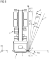
- the respective printed circuit board 8, 9 with the at least one IR LED 10, 11 attached thereto can additionally be inclined in the X,Y plane by the horizontal angle ⁇ XY with respect to the X axis or horizontal.
- the truck from Figs. 4 , 6 and 7 is shown in a top view.
- the first printed circuit board 8 By tilting the first printed circuit board 8 with its at least one first IR LED 10 with respect to the X-axis or horizontal by the horizontal near angle ⁇ 1XY, a near area on the vehicle can be lit up.
- the light cone 5 of the at least one first IR LED 10 with the beam angle ⁇ 1 as the near area thereby lights up the area directly along the longitudinal side of the vehicle.
- the light cone 5 runs with its first mantle line in the longitudinal direction of the vehicle parallel to the truck 1.
- the second printed circuit board 9 By tilting the second printed circuit board 9 with its at least one second IR LED 11 relative to the X axis or horizontal by the horizontal far angle ⁇ 2XY, a far area on the vehicle 1 can be lit up.
- the light cone 5 of the at least one second IR LED 11 with the beam angle ⁇ 2 as the far area thereby lights up the area adjacent to the near area.
- the horizontal near angle ⁇ 1XY and the horizontal far angle ⁇ 2XY can also be selected such that the two light cones 5, 5 at least partially overlap, for example.
- At least the horizontal near angle ⁇ 1XY or the horizontal far angle ⁇ 2XY can be selected in such a way that the respective light cone 5, 5 is directed or pivoted further inwards in the direction of the vehicle 1, instead of comprising a parallel path in the longitudinal direction of the vehicle, as in Fig. 8 .
- a part inside the vehicle 1, for example the loading area of the trailer 2 of the truck can also be lit up by the light cone 5.
- at least the horizontal near angle ⁇ 1XY or the horizontal far angle ⁇ 2XY are selected in such a way that the respective light cone 5, 5 is directed or pivoted outwards against the direction of the vehicle 1. In this way, a part outside the vehicle 1 can be lit up, as shown in Fig. 8 for the horizontal remote angle ⁇ 2XY.
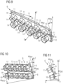
- FIGs. 9 and 10 perspective views of an embodiment of the infrared lighting device 6 according to the invention are shown in each case, with the heat sink 12, 13 of the respective printed circuit board 8, 9 being shown only in Fig. 9 for reasons of clarity.
- Fig. 11 further shows a side view of the infrared lighting device 6 according to Figs. 9 and 10 .
- the infrared lighting device 6 thereby comprises at least a first printed circuit board 8 with at least one or two first IR LEDs 10, for example five first IR LEDs 10.
- the first IR LEDs 10 are thereby provided, for example, with an additional lens or lens device 14 for focusing the light and reducing stray light.
- the lighting device 6 comprises at least one second printed circuit board 9 with at least one or two second IR LEDs 11, for example five second IR LEDs 11.
- the second IR LEDs 11 are thereby also provided, for example, with an additional lens or lens device 14 for bundling the light and reducing the stray light.
- the respective first and second IR LEDs 10, 11 are attached vertically to the first and second printed circuit boards 8, 9.
- the cone axis R1, R2 of the first or second IR LED 10, 11 is thus perpendicular to the first or second printed circuit board 8, 9, respectively.
- at least one, several or all IR LEDs 10, 11 are each provided with an additional lens device 14 as an example of an optical element for bundling the light and reducing the stray light.
- the respective first IR LED 10 thereby comprises a beam angle ⁇ 1 and the respective second IR LED 11 comprises a beam angle ⁇ 2.
- the beam angles ⁇ 1, ⁇ 2 may be identical or different in size. ⁇ 1 can be larger than ⁇ 2 or, conversely, ⁇ 2 can be larger than ⁇ 1.
- the respective first IR LED may further comprise an emission power I1 and the respective second IR LED may comprise an emission power I2.
- the emission powers I1 and I2 may be identical or different in magnitude. I1 may be greater than I2 or vice versa and I2 may be greater than I1, depending on the function and intended use.
- the respective first or second printed circuit board 8, 9 is thereby further coupled in each case to a heat sink 12, 13 for dissipating the heat generated by the respective IR LED 10, 11, as shown in Fig. 11 .
- heat sink 12, 13, for example, at least one plate-shaped heat sink and, in particular, a plate made of a thermally conductive material or material combination, for example made of a thermally conductive metal or metal alloy, in particular aluminum and/or copper, is thereby provided.
- the heat sink 12, 13 is thereby attached to the rear side of the first or second printed circuit board 8, 9, preferably directly attached thereto.
- the invention is not limited to a heat sink 12, 13 in the form of a thermally conductive plate, any other form of heat sink 12, 13 can be provided which is suitable for dissipating the heat generated by the respective IR LED 10, 11.
- the plate may be flat as well as provided with additional cooling elements, e.g. cooling fins etc., on at least one side.
- the heat sink 12, 13 preferably extends over the entire area of the printed circuit board 8, 9 or at least the area of the printed circuit board 8, 9 to which the at least one IR LED 10, 11 is attached and can, for example, lie flat against it.
- the first printed circuit board 8 with the respective first IR LED 10 attached vertically thereto is used for lighting up the first partial area, in particular the near area
- the second printed circuit board 9 with the respective second IR LED 11 attached vertically thereto is used for lighting up the second partial area, in particular the far area, of the vehicle, e.g. truck, as described previously with reference to Figs. 3-8 .
- the first printed circuit board 8 with the respective first IR lamp 10 attached vertically thereto is thereby inclined by a vertical near angle ⁇ 1zx with respect to the vertical (Z axis) and by a horizontal near angle ⁇ 1XY with respect to the horizontal (X axis), for illuminating a first partial area, in particular near area, of the vehicle 1 in the longitudinal direction of the vehicle, as previously described with reference to Figs. 3-8 .
- the second printed circuit board 9 with the second IR lamp 11 attached vertically thereto in each case is inclined by a vertical far angle O2xz with respect to the vertical (Z axis) and by a horizontal far angle ⁇ 2XY with respect to the horizontal (X axis), for illuminating a second partial area, in particular far area, of the vehicle 1 in the longitudinal direction of the vehicle, as described previously with reference to Figs. 3-8 .
- the infrared lighting device 6 is shown as part of a camera monitoring (CMS) system (CMS Camera Montoring System), as previously described by way of example with reference to Figs. 1 and 2 .
- CMS system comprises the at least one camera, e.g. an infrared sensitive camera, for recording the predetermined vehicle area and preferably the predetermined vehicle area illuminated by the infrared lighting device 6 as described previously with reference to Figs. 3-11 .
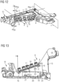
- Figs. 12-15 show a holder 15 to which the infrared lighting device 6 is attached with its first circuit board 8 having, for example, five first IR lamps 10 and its second circuit board 9 also having, for example, five second IR lamps 11.
- the two printed circuit boards 8, 9 are thereby fastened, for example, one above the other in the Z direction or in the vertical direction in the installation position on a vehicle.
- a dashed line indicates the attachment to the vehicle 1, e.g. here the longitudinal side of the vehicle.
- the bracket 15 thus stands like a wing laterally outward or in the Y-direction or transverse direction of the vehicle.
- the holder 15 comprises at least two fastening flanges 16, 17 in each case, to which the associated first or second printed circuit board 8, 9 with its heat sink 12, 13 is fastened at the rear.
- the at least two fastening flanges 16, 17 can be arranged and aligned on the holder 15 in such a way that they already specify the vertical angle OXZ and/or horizontal angle ⁇ XY of the respective PCB to be fastened thereto.
- the holder 15 comprises a recess in which the mounting flanges 16, 17 are arranged and the printed circuit boards 8, 9 are received for mounting.
- the holder 15 in the example in Figs. 12-15 also comprises a receptacle 18 for an infrared sensitive camera, in particular the infrared sensitive camera 28 of the CMS system 29.
- the CMS system 29 can comprise further cameras for recording visual images of the vehicle both during the day and at night.
- the lighting start point 19 is provided behind the printed circuit boards 8, 9 with their heat sinks 12, 13, as shown in Fig. 13 .
- the lighting controller 19 with its main board 20 comprises an output connector 21 for each of the first and second printed circuit boards 8, 9 with their first and second IR LEDs 10, 11, respectively, as well as an input connector 22 for connection to a controller of the at least one camera, e.g. infrared sensitive camera, in particular the controller of the CMS system and its at least one camera, e.g., infrared sensitive camera.
- the mount 15 further comprises a cable opening 23 for passing cable lines therethrough.
- each circuit board 8, 9 comprises its own first and second lighting start point, respectively.
- This first or second lighting controller thereby comprises an input connector for connecting the controller of the camera, e.g., infrared sensitive camera, in particular the controller of the CMS system 29 and its at least one camera 28, e.g., infrared sensitive camera 28.
- the first or second lighting controller comprises an output connector for the first or second printed circuit board with its first or second IR LEDs, respectively.
- the respective first and second printed circuit board with its first and, respectively, second lighting controller is arranged on a first and, respectively, second holder in a first and, respectively, second housing.
- the holder 15 with the lighting device 6 is accommodated in the associated housing 24, for example a wing housing that is attached to the driver's cabin, for example, and protrudes laterally from the vehicle like a wing.
- the housing 24 thereby comprises a housing shell 25 which is closed by a housing cover 26.
- the housing 24, for example its housing shell 25, comprises a camera opening 27 for the camera 28, e.g., infrared sensitive camera 28 and optionally, for example, at least one further camera of the CMS system 29.
- the housing cover 26 is transparent to the infrared radiation of the IR LEDs 10, 11 of the two printed circuit boards 8, 9, at least in the region of the IR LEDs 10, 11.
- the infrared lighting device 6 may be coupled to a camera monitoring system (CMS) 29 comprising at least one camera 28, e.g., an infrared sensitive camera 28, as previously described.
- CMS system 29 may determine, based on a detected vehicle ambient brightness, that the vehicle ambient brightness is no longer sufficient, for example at advanced dusk, at darkness, or a vehicle shadow, and therefore control the infrared lighting device 6 to light up the vehicle in the field of view of the camera 28, in particular infrared sensitive camera 28, by means of its IR LEDs 10, 122 in a predetermined area in the longitudinal direction of the vehicle.
- the CMS system 29 can thereby, for example, depending on at least one parameter such as a desired emission power of the infrared lighting device 6, a size of the predetermined area to be illuminated and/or a size of the respective at least first and second partial areas of the predetermined area to be illuminated of the vehicle, control the lighting device to at least switch on or off and/or dim a suitable number of the plurality of first and second IR lamps 10, 11.
- at least one of the five first IR LEDs 10 of the first circuit board 8 may be sufficient to light up the first partial area of a predetermined area of the vehicle to be illuminated.
- the CMS system 29 can control the infrared lighting device 6 in such a way as to, e.g., alternately always switch on or off or dim a predetermined number and/or predetermined pairing of several of the first IR LEDs 10, respectively, and/or to alternately always switch on or off or dim a predetermined number and/or predetermined pairing of several of the first IR LEDs 11, respectively, of all the second IR LEDs 11.
- the image processing device of the CMS system 29 can use at least one object recognition algorithm to determine a person in a light cone of an IR lamp, in this case the respective first IR lamp 10 and/or second IR lamp 11, and additionally a distance of the person to this respective IR lamp, here the first IR lamp 10 or second IR lamp 11.
- the CMS system 29 can switch off or dim down the respective first or second IR lamp 10, 11 of the first or second printed circuit board 8, 9, respectively, if the image processing device described above with reference to Fig.1 and 2 detects a person or living being in the light cone of this IR lamp and preferably a distance of the person or living being from this IR lamp falls below an assigned eye safety distance.
- the CMS system 29 can switch on or dim up this IR lamp again as soon as no person is detected in the light cone anymore or the person detected in the light cone comprises a distance to this IR lamp that is equal to or greater than the assigned eye safety distance.
- CMS system 29 turns off or dims down the respective IR LED to an allowable emission power and turns it back on or dims it up to an output emission power once the person or living being has stepped out of the light cone of the IR LED or resumes the eye safety distance specified for the IR LED.
- the infrared lighting device is not limited to two first and second circuit boards each having five first and second IR LEDs.
- one or more first circuit boards may be provided each comprising at least one, two, three, four, five, or a plurality of first IR LEDs, depending on the function and intended use.
- one or more second printed circuit boards may be provided each comprising at least one, two, three, four, five or a plurality of second IR LEDs, depending on the function and intended use.
Landscapes
- Engineering & Computer Science (AREA)
- Multimedia (AREA)
- Physics & Mathematics (AREA)
- General Physics & Mathematics (AREA)
- Theoretical Computer Science (AREA)
- Signal Processing (AREA)
- Health & Medical Sciences (AREA)
- General Health & Medical Sciences (AREA)
- Oral & Maxillofacial Surgery (AREA)
- Human Computer Interaction (AREA)
- General Engineering & Computer Science (AREA)
- Closed-Circuit Television Systems (AREA)
Applications Claiming Priority (1)
| Application Number | Priority Date | Filing Date | Title |
|---|---|---|---|
| DE102023121029 | 2023-08-08 |
Publications (1)
| Publication Number | Publication Date |
|---|---|
| EP4521734A1 true EP4521734A1 (de) | 2025-03-12 |
Family
ID=92264200
Family Applications (1)
| Application Number | Title | Priority Date | Filing Date |
|---|---|---|---|
| EP24193385.2A Pending EP4521734A1 (de) | 2023-08-08 | 2024-08-07 | Kameraüberwachungssystem für ein fahrzeug, verfahren zur steuerung des kameraüberwachungssystems und fahrzeug |
Country Status (2)
| Country | Link |
|---|---|
| US (1) | US20250054314A1 (de) |
| EP (1) | EP4521734A1 (de) |
Families Citing this family (1)
| Publication number | Priority date | Publication date | Assignee | Title |
|---|---|---|---|---|
| US12422301B2 (en) * | 2023-09-01 | 2025-09-23 | Harman International Industries, Incorporated | Infrared emitter checking circuit and method |
Citations (4)
| Publication number | Priority date | Publication date | Assignee | Title |
|---|---|---|---|---|
| US20160248957A1 (en) * | 2015-02-25 | 2016-08-25 | Lg Electronics Inc. | Digital device and driver monitoring method thereof |
| WO2020126396A1 (en) | 2018-12-17 | 2020-06-25 | Orlaco Products B.V. | Camera mirror system with ir led night vision system |
| US20210365702A1 (en) * | 2018-04-19 | 2021-11-25 | Seeing Machines Limited | Infrared light source protective system |
| EP4032751A1 (de) * | 2019-09-19 | 2022-07-27 | Koito Manufacturing Co., Ltd. | Infrarot-beleuchtungsanlage für fahrzeuge, infrarot-sensorsystem für fahrzeuge und beleuchtungseinheit mit eingebautem infrarotsensor und beleuchtungseinheit mit eingebautem optischen sensor für fahrzeuge |
Family Cites Families (22)
| Publication number | Priority date | Publication date | Assignee | Title |
|---|---|---|---|---|
| US6107618A (en) * | 1997-07-14 | 2000-08-22 | California Institute Of Technology | Integrated infrared and visible image sensors |
| US7057256B2 (en) * | 2001-05-25 | 2006-06-06 | President & Fellows Of Harvard College | Silicon-based visible and near-infrared optoelectric devices |
| KR100648308B1 (ko) * | 2004-08-12 | 2006-11-23 | 삼성전자주식회사 | 해상도 변환방법 및 장치 |
| WO2006060746A2 (en) * | 2004-12-03 | 2006-06-08 | Infrared Solutions, Inc. | Visible light and ir combined image camera with a laser pointer |
| KR101299074B1 (ko) * | 2006-03-03 | 2013-08-30 | 허니웰 인터내셔널 인코포레이티드 | 홍채 인코딩 시스템 |
| US7629582B2 (en) * | 2006-10-24 | 2009-12-08 | Raytheon Company | Dual band imager with visible or SWIR detectors combined with uncooled LWIR detectors |
| US8159519B2 (en) * | 2007-05-31 | 2012-04-17 | Eastman Kodak Company | Personal controls for personal video communications |
| WO2009117603A2 (en) * | 2008-03-19 | 2009-09-24 | Hypermed, Inc. | Miniaturized multi-spectral imager for real-time tissue oxygenation measurement |
| US20090273675A1 (en) * | 2008-05-05 | 2009-11-05 | Flir Systems Ab | Ir camera and method for use with ir camera |
| US7915652B2 (en) * | 2008-10-24 | 2011-03-29 | Sharp Laboratories Of America, Inc. | Integrated infrared and color CMOS imager sensor |
| US8520970B2 (en) * | 2010-04-23 | 2013-08-27 | Flir Systems Ab | Infrared resolution and contrast enhancement with fusion |
| US20140267757A1 (en) * | 2013-03-15 | 2014-09-18 | Fluke Corporation | Parallax correction in thermal imaging cameras |
| KR102050418B1 (ko) * | 2013-08-20 | 2019-12-02 | 한화테크윈 주식회사 | 영상 정합 장치 및 이를 이용한 영상 정합 방법 |
| WO2016197010A1 (en) * | 2015-06-05 | 2016-12-08 | Flir Systems, Inc. | Systems and methods for enhanced dynamic range infrared imaging |
| US10152811B2 (en) * | 2015-08-27 | 2018-12-11 | Fluke Corporation | Edge enhancement for thermal-visible combined images and cameras |
| GB2577646B (en) * | 2017-06-03 | 2022-09-14 | Teledyne FLIR LLC | Extensible architecture for surveillance and targeting imaging systems and methods |
| US10684370B2 (en) * | 2017-09-29 | 2020-06-16 | Veoneer Us, Inc. | Multifunction vehicle detection system |
| US20190141236A1 (en) * | 2017-11-06 | 2019-05-09 | Fluke Corporation | Inspection workflow using ojbect recognition and other techniques |
| US10850693B1 (en) * | 2018-04-05 | 2020-12-01 | Ambarella International Lp | Determining comfort settings in vehicles using computer vision |
| US10960838B2 (en) * | 2019-01-30 | 2021-03-30 | Cobalt Industries Inc. | Multi-sensor data fusion for automotive systems |
| US11336741B2 (en) * | 2019-11-01 | 2022-05-17 | Microsoft Technology Licensing, Llc | Image data segmentation and transmission |
| US11816905B2 (en) * | 2020-03-19 | 2023-11-14 | Magna Electronics Inc. | Multi-camera vision system integrated into interior rearview mirror |
-
2024
- 2024-08-07 EP EP24193385.2A patent/EP4521734A1/de active Pending
- 2024-08-08 US US18/798,333 patent/US20250054314A1/en active Pending
Patent Citations (4)
| Publication number | Priority date | Publication date | Assignee | Title |
|---|---|---|---|---|
| US20160248957A1 (en) * | 2015-02-25 | 2016-08-25 | Lg Electronics Inc. | Digital device and driver monitoring method thereof |
| US20210365702A1 (en) * | 2018-04-19 | 2021-11-25 | Seeing Machines Limited | Infrared light source protective system |
| WO2020126396A1 (en) | 2018-12-17 | 2020-06-25 | Orlaco Products B.V. | Camera mirror system with ir led night vision system |
| EP4032751A1 (de) * | 2019-09-19 | 2022-07-27 | Koito Manufacturing Co., Ltd. | Infrarot-beleuchtungsanlage für fahrzeuge, infrarot-sensorsystem für fahrzeuge und beleuchtungseinheit mit eingebautem infrarotsensor und beleuchtungseinheit mit eingebautem optischen sensor für fahrzeuge |
Also Published As
| Publication number | Publication date |
|---|---|
| US20250054314A1 (en) | 2025-02-13 |
Similar Documents
| Publication | Publication Date | Title |
|---|---|---|
| US6993255B2 (en) | Method and apparatus for providing adaptive illumination | |
| CN111263710B (zh) | 集成机动车自适应驱动光束前照灯和校准方法 | |
| US11104279B2 (en) | Vehicle vision system with adaptive reversing light | |
| US8830324B2 (en) | Vehicle monitoring camera and vehicle monitoring camera system | |
| US6550949B1 (en) | Systems and components for enhancing rear vision from a vehicle | |
| US7646884B2 (en) | Active night vision image intensity balancing system | |
| US7935928B2 (en) | Device and method for producing images | |
| US10356337B2 (en) | Vehicle vision system with gray level transition sensitive pixels | |
| US8581982B1 (en) | Infrared camera vehicle integration systems and methods | |
| US6967569B2 (en) | Active night vision with adaptive imaging | |
| KR100682067B1 (ko) | 차량 전조등들이나 또는 타의 차량 장비를 제어하기 위한 영상 처리 시스템 | |
| CN111526266B (zh) | 多功能摄影系统 | |
| EP3139585B1 (de) | Integrierte einheit mit kamera, umgebungslichterkennung und regensensor | |
| WO2002004247A1 (en) | Method and apparatus for providing adaptive illumination | |
| US20060018513A1 (en) | Stereo vehicle-exterior monitoring apparatus | |
| JP2006188224A (ja) | 車両用暗視システム、光源操作システム及びその制御方法 | |
| EP1168007A2 (de) | Dünne Reflexionsfolie und Nachtsichtsystem | |
| US20070069135A1 (en) | Method and device for controlling a radiation source | |
| JP5500442B2 (ja) | 低照度対応カメラ | |
| US20200200356A1 (en) | Ir illuminator with secondary function | |
| US20250054314A1 (en) | Camera monitoring (CMS) system for a vehicle, method of controlling the camera monitoring (CMS) system, and vehicle | |
| KR102481310B1 (ko) | 자동차 헤드램프용 조명 장치 | |
| CN108780230A (zh) | 用于利用红外光照射车辆的驾驶员的照明设备、驾驶员观测系统和抬头显示单元 | |
| US20230173996A1 (en) | Camera Wing System, Vehicle Therewith and Method to Operate the Same | |
| JP2025184753A (ja) | 車両用ランプシステム |
Legal Events
| Date | Code | Title | Description |
|---|---|---|---|
| PUAI | Public reference made under article 153(3) epc to a published international application that has entered the european phase |
Free format text: ORIGINAL CODE: 0009012 |
|
| STAA | Information on the status of an ep patent application or granted ep patent |
Free format text: STATUS: THE APPLICATION HAS BEEN PUBLISHED |
|
| AK | Designated contracting states |
Kind code of ref document: A1 Designated state(s): AL AT BE BG CH CY CZ DE DK EE ES FI FR GB GR HR HU IE IS IT LI LT LU LV MC ME MK MT NL NO PL PT RO RS SE SI SK SM TR |
|
| STAA | Information on the status of an ep patent application or granted ep patent |
Free format text: STATUS: REQUEST FOR EXAMINATION WAS MADE |
|
| 17P | Request for examination filed |
Effective date: 20250911 |
|
| RAP3 | Party data changed (applicant data changed or rights of an application transferred) |
Owner name: MOTHERSON INNOVATIONS COMPANY LIMITED |