EP4521740A2 - Verfahren und vorrichtung zur videodecodierung, verfahren und vorrichtung zur videocodierung, verfahren zur speicherung eines videobitstroms und computerlesbares medium - Google Patents
Verfahren und vorrichtung zur videodecodierung, verfahren und vorrichtung zur videocodierung, verfahren zur speicherung eines videobitstroms und computerlesbares medium Download PDFInfo
- Publication number
- EP4521740A2 EP4521740A2 EP25153956.5A EP25153956A EP4521740A2 EP 4521740 A2 EP4521740 A2 EP 4521740A2 EP 25153956 A EP25153956 A EP 25153956A EP 4521740 A2 EP4521740 A2 EP 4521740A2
- Authority
- EP
- European Patent Office
- Prior art keywords
- picture
- flag
- layer
- equal
- sub
- Prior art date
- Legal status (The legal status is an assumption and is not a legal conclusion. Google has not performed a legal analysis and makes no representation as to the accuracy of the status listed.)
- Pending
Links
Images











Classifications
-
- H—ELECTRICITY
- H04—ELECTRIC COMMUNICATION TECHNIQUE
- H04N—PICTORIAL COMMUNICATION, e.g. TELEVISION
- H04N19/00—Methods or arrangements for coding, decoding, compressing or decompressing digital video signals
- H04N19/10—Methods or arrangements for coding, decoding, compressing or decompressing digital video signals using adaptive coding
- H04N19/102—Methods or arrangements for coding, decoding, compressing or decompressing digital video signals using adaptive coding characterised by the element, parameter or selection affected or controlled by the adaptive coding
- H04N19/103—Selection of coding mode or of prediction mode
- H04N19/105—Selection of the reference unit for prediction within a chosen coding or prediction mode, e.g. adaptive choice of position and number of pixels used for prediction
-
- H—ELECTRICITY
- H04—ELECTRIC COMMUNICATION TECHNIQUE
- H04N—PICTORIAL COMMUNICATION, e.g. TELEVISION
- H04N19/00—Methods or arrangements for coding, decoding, compressing or decompressing digital video signals
- H04N19/10—Methods or arrangements for coding, decoding, compressing or decompressing digital video signals using adaptive coding
- H04N19/102—Methods or arrangements for coding, decoding, compressing or decompressing digital video signals using adaptive coding characterised by the element, parameter or selection affected or controlled by the adaptive coding
- H04N19/103—Selection of coding mode or of prediction mode
- H04N19/11—Selection of coding mode or of prediction mode among a plurality of spatial predictive coding modes
-
- H—ELECTRICITY
- H04—ELECTRIC COMMUNICATION TECHNIQUE
- H04N—PICTORIAL COMMUNICATION, e.g. TELEVISION
- H04N19/00—Methods or arrangements for coding, decoding, compressing or decompressing digital video signals
- H04N19/10—Methods or arrangements for coding, decoding, compressing or decompressing digital video signals using adaptive coding
- H04N19/134—Methods or arrangements for coding, decoding, compressing or decompressing digital video signals using adaptive coding characterised by the element, parameter or criterion affecting or controlling the adaptive coding
- H04N19/157—Assigned coding mode, i.e. the coding mode being predefined or preselected to be further used for selection of another element or parameter
- H04N19/159—Prediction type, e.g. intra-frame, inter-frame or bidirectional frame prediction
-
- H—ELECTRICITY
- H04—ELECTRIC COMMUNICATION TECHNIQUE
- H04N—PICTORIAL COMMUNICATION, e.g. TELEVISION
- H04N19/00—Methods or arrangements for coding, decoding, compressing or decompressing digital video signals
- H04N19/10—Methods or arrangements for coding, decoding, compressing or decompressing digital video signals using adaptive coding
- H04N19/169—Methods or arrangements for coding, decoding, compressing or decompressing digital video signals using adaptive coding characterised by the coding unit, i.e. the structural portion or semantic portion of the video signal being the object or the subject of the adaptive coding
- H04N19/17—Methods or arrangements for coding, decoding, compressing or decompressing digital video signals using adaptive coding characterised by the coding unit, i.e. the structural portion or semantic portion of the video signal being the object or the subject of the adaptive coding the unit being an image region, e.g. an object
- H04N19/172—Methods or arrangements for coding, decoding, compressing or decompressing digital video signals using adaptive coding characterised by the coding unit, i.e. the structural portion or semantic portion of the video signal being the object or the subject of the adaptive coding the unit being an image region, e.g. an object the region being a picture, frame or field
-
- H—ELECTRICITY
- H04—ELECTRIC COMMUNICATION TECHNIQUE
- H04N—PICTORIAL COMMUNICATION, e.g. TELEVISION
- H04N19/00—Methods or arrangements for coding, decoding, compressing or decompressing digital video signals
- H04N19/10—Methods or arrangements for coding, decoding, compressing or decompressing digital video signals using adaptive coding
- H04N19/169—Methods or arrangements for coding, decoding, compressing or decompressing digital video signals using adaptive coding characterised by the coding unit, i.e. the structural portion or semantic portion of the video signal being the object or the subject of the adaptive coding
- H04N19/188—Methods or arrangements for coding, decoding, compressing or decompressing digital video signals using adaptive coding characterised by the coding unit, i.e. the structural portion or semantic portion of the video signal being the object or the subject of the adaptive coding the unit being a video data packet, e.g. a network abstraction layer [NAL] unit
-
- H—ELECTRICITY
- H04—ELECTRIC COMMUNICATION TECHNIQUE
- H04N—PICTORIAL COMMUNICATION, e.g. TELEVISION
- H04N19/00—Methods or arrangements for coding, decoding, compressing or decompressing digital video signals
- H04N19/30—Methods or arrangements for coding, decoding, compressing or decompressing digital video signals using hierarchical techniques, e.g. scalability
-
- H—ELECTRICITY
- H04—ELECTRIC COMMUNICATION TECHNIQUE
- H04N—PICTORIAL COMMUNICATION, e.g. TELEVISION
- H04N19/00—Methods or arrangements for coding, decoding, compressing or decompressing digital video signals
- H04N19/46—Embedding additional information in the video signal during the compression process
-
- H—ELECTRICITY
- H04—ELECTRIC COMMUNICATION TECHNIQUE
- H04N—PICTORIAL COMMUNICATION, e.g. TELEVISION
- H04N19/00—Methods or arrangements for coding, decoding, compressing or decompressing digital video signals
- H04N19/50—Methods or arrangements for coding, decoding, compressing or decompressing digital video signals using predictive coding
- H04N19/503—Methods or arrangements for coding, decoding, compressing or decompressing digital video signals using predictive coding involving temporal prediction
- H04N19/51—Motion estimation or motion compensation
- H04N19/573—Motion compensation with multiple frame prediction using two or more reference frames in a given prediction direction
-
- H—ELECTRICITY
- H04—ELECTRIC COMMUNICATION TECHNIQUE
- H04N—PICTORIAL COMMUNICATION, e.g. TELEVISION
- H04N19/00—Methods or arrangements for coding, decoding, compressing or decompressing digital video signals
- H04N19/50—Methods or arrangements for coding, decoding, compressing or decompressing digital video signals using predictive coding
- H04N19/503—Methods or arrangements for coding, decoding, compressing or decompressing digital video signals using predictive coding involving temporal prediction
- H04N19/51—Motion estimation or motion compensation
- H04N19/58—Motion compensation with long-term prediction, i.e. the reference frame for a current frame not being the temporally closest one
-
- H—ELECTRICITY
- H04—ELECTRIC COMMUNICATION TECHNIQUE
- H04N—PICTORIAL COMMUNICATION, e.g. TELEVISION
- H04N19/00—Methods or arrangements for coding, decoding, compressing or decompressing digital video signals
- H04N19/50—Methods or arrangements for coding, decoding, compressing or decompressing digital video signals using predictive coding
- H04N19/597—Methods or arrangements for coding, decoding, compressing or decompressing digital video signals using predictive coding specially adapted for multi-view video sequence encoding
-
- H—ELECTRICITY
- H04—ELECTRIC COMMUNICATION TECHNIQUE
- H04N—PICTORIAL COMMUNICATION, e.g. TELEVISION
- H04N19/00—Methods or arrangements for coding, decoding, compressing or decompressing digital video signals
- H04N19/70—Methods or arrangements for coding, decoding, compressing or decompressing digital video signals characterised by syntax aspects related to video coding, e.g. related to compression standards
Definitions
- Embodiments of the present disclosure relate to video coding and decoding, and more specifically, to random access picture and its output process in a coded video stream with multiple layers.
- Uncompressed digital video can include a series of pictures, each picture having a spatial dimension of, for example, 1920 x 1080 luminance samples and associated chrominance samples.
- the series of pictures can have a fixed or variable picture rate (informally also known as frame rate), of, for example 60 pictures per second or 60 Hz.
- Uncompressed video has significant bitrate requirements. For example, 1080p60 4:2:0 video at 8 bit per sample (1920 ⁇ 1080 luminance sample resolution at 60 Hz frame rate) requires close to 1.5 Gbit/s bandwidth. An hour of such video requires more than 600 GByte of storage space.
- Video coding and decoding can be the reduction of redundancy in the input video signal, through compression. Compression can help reduce aforementioned bandwidth or storage space requirements, in some cases by two orders of magnitude or more. Both lossless and lossy compression, as well as a combination thereof can be employed. Lossless compression refers to techniques where an exact copy of the original signal can be reconstructed from the compressed original signal. When using lossy compression, the reconstructed signal may not be identical to the original signal, but the distortion between original and reconstructed signal may be small enough to make the reconstructed signal useful for the intended application. In the case of video, lossy compression is widely employed. The amount of distortion tolerated depends on the application; for example, users of certain consumer streaming applications may tolerate higher distortion than users of television contribution applications. The compression ratio achievable can reflect that: higher allowable/tolerable distortion can yield higher compression ratios.
- a video encoder and decoder can utilize techniques from several broad categories, including, for example, motion compensation, transform, quantization, and entropy coding, some of which will be introduced below.
- video encoders and decoders tended to operate on a given picture size that was, in most cases, defined and stayed constant for a coded video sequence (CVS), Group of Pictures (GOP), or a similar multi-picture timeframe.
- CVS coded video sequence
- GOP Group of Pictures
- MPEG-2 system designs were used to change the horizontal resolution (and, thereby, the picture size) dependent on factors such as activity of the scene, but only at I pictures, hence typically for a GOP.
- the resampling of reference pictures for use of different resolutions within a CVS has been used in, for example, ITU-T Rec. H.263 Annex P.
- H.263 Annex Q allows the resampling of an individual macroblock by a factor of two (in each dimension), upward or downward. Again, the picture size remains the same.
- the size of a macroblock is fixed in H.263, and therefore does not need to be signaled.
- NAL network abstraction layer
- an intra random access point (IRAP) picture may enable the random access to an intermedia point of the bitstream and successful decoding of the video bitstream at the random access point.
- One of possible methods is the gradual refresh of the scene with some amount of recovery time.
- the gradual decoding refresh (GDR) picture and access unit (AU) are defined to specify syntax and semantics of the random access operation with gradual decoding refresh.
- GDR gradual decoding refresh
- AU access unit
- one or more pictures may be unavailable due to random access or unintended picture loss.
- it is desired to generate unavailable pictures with defaults values of pixels and parameters. After generating unavailable pictures, it may be needed to check the validation of all reference pictures in reference picture list.
- Embodiments of the present disclosure relate to random access picture and its output process in a coded video stream with multiple layers. Embodiments of the present disclosure related to random access picture and its leading picture output indication in a coded video stream with multiple layers. Embodiments of the present disclosure relate to signaling random access pictures with gradual decoding refresh and recovery point in a coded video stream with multiple layers. Embodiments of the present disclosure relate to reference picture list construction and unavailable picture generation in a coded video stream with multiple layers. Embodiments of the present disclosure include techniques for signaling of adaptive picture size in a video bitstream.
- One or more embodiments of the present disclosure include a method performed by at least one processor.
- the method includes: receiving a coded video stream that includes an access unit, including a picture; signaling a first flag, in an access unit delimiter of the coded video stream, that indicates whether the access unit includes either or neither one from among an intra random access point (IRAP) picture and a gradual decoding refresh (GDR) picture; signaling a second flag, in a picture header of the coded video stream, that indicates whether the picture is the IRAP picture; and decoding the picture, as a current picture, based on the signaling of the first flag and the second flag, wherein a value of the first flag and a value of the second flag are aligned.
- IRAP intra random access point
- GDR gradual decoding refresh
- the method further includes: signaling a third flag, in the picture header of the coded video stream, that indicates whether the picture is the GDR picture, wherein the value of the first flag and a value of the third flag are aligned.
- the third flag is signaled based on the second flag indicating that the picture is not the IRAP picture.
- the first flag has a value that indicates that the picture is either one from among the IRAP picture and the GDR picture
- the second flag has a value that indicates that the picture is the IRAP picture
- the method further includes signaling a third flag, in a slice header of a slice of the picture of the coded video stream, that indicates whether any pictures prior to the IRAP picture are outputted.
- the method further includes: determining a network abstraction layer (NAL) unit type of the slice, wherein the third flag is signalled based on the NAL unit type that is determined.
- NAL network abstraction layer
- the third flag is signalled based on the NAL unit type being determined to be equal to IDR_W_RADL, IDR_N_LP, or CRA_NUT.
- the method further includes: signaling a fourth flag, in the picture header of the coded video stream, that indicates whether the picture is the GDR picture, wherein the value of the first flag and a value of the fourth flag are aligned.
- the third flag is signaled based on the second flag indicating that the picture is not the IRAP picture.
- the decoding includes: constructing a reference picture list; generating an unavailable reference picture in the reference picture list; and checking bitstream conformance, for references pictures in the reference picture list, that the following constraints apply: a number of entries that are indicated to be in the reference picture list is not less than a number of active entries that are indicated to be in the reference picture list, each picture referred to by an active entry in the reference picture list is present in a decoded picture buffer (DPB) and has a temporal identifier value less than or equal to a temporal identifier value of the current picture, and each picture referred to by an entry in the reference picture list is not the current picture and is indicated by a picture header flag to potentially be a reference picture.
- DPB decoded picture buffer
- the checking bistream conformance is performed based on determining the current picture is an independent decoder refresh (IDR) picture, a clean random access (CRA) picture, or a gradual decoding refresh (GDR) picture.
- IDR independent decoder refresh
- CRA clean random access
- GDR gradual decoding refresh
- a system includes: at least one processor that is configured to receive a coded video stream that includes an access unit, including a picture; and memory storing computer code, the computer code including: first signaling code configured to cause the at least one processor to signal a first flag, in an access unit delimiter of the coded video stream, that indicates whether the access unit includes either or neither one from among an intra random access point (IRAP) picture and a gradual decoding refresh (GDR) picture; second signaling code configured to cause the at least one processor to signal a second flag, in a picture header of the coded video stream, that indicates whether the picture is the IRAP picture; and decoding code configured to cause the at least one processor to decode the picture, as a current picture, based on the signaling of the first flag and the second flag, wherein a value of the first flag and a value of the second flag are aligned.
- first signaling code configured to cause the at least one processor to signal a first flag, in an access unit delimiter of the coded video stream, that indicates whether
- the computer code further includes: third signaling code configured to cause the at least one processor to signal a third flag, in the picture header of the coded video stream, that indicates whether the picture is the GDR picture, wherein the value of the first flag and a value of the third flag are aligned.
- the third flag is signaled based on the second flag indicating that the picture is not the IRAP picture.
- the first flag has a value that indicates that the picture is either one from among the IRAP picture and the GDR picture
- the second flag has a value that indicates that the picture is the IRAP picture
- the compute code further includes third signaling code configured to cause the at least one processor to signal a third flag, in a slice header of a slice of the picture of the coded video stream, that indicates whether any pictures prior to the IRAP picture are outputted.
- the computer code further includes: determining code configured to cause the at least one processor to determine a network abstraction layer (NAL) unit type of the slice, wherein the third flag is signalled based on the NAL unit type that is determined.
- NAL network abstraction layer
- the third flag is signalled based on the NAL unit type being determined to be equal to IDR_W_RADL, IDR_N_LP, or CRA_NUT.
- the computer code further includes: fourth signaling codec configured to cause the at least one processor to signal a fourth flag, in the picture header of the coded video stream, that indicates whether the picture is the GDR picture, wherein the value of the first flag and a value of the fourth flag are aligned.
- the third flag is signaled based on the second flag indicating that the picture is not the IRAP picture.
- the decoding code includes: constructing code configured to cause the at least one processor to construct a reference picture list; generating code configured to cause the at least one processor to generate an unavailable reference picture in the reference picture list; and checking code configured to cause the at least one processor to check bitstream conformance, for references pictures in the reference picture list, that the following constraints apply: a number of entries that are indicated to be in the reference picture list is not less than a number of active entries that are indicated to be in the reference picture list, each picture referred to by an active entry in the reference picture list is present in a decoded picture buffer (DPB) and has a temporal identifier value less than or equal to a temporal identifier value of the current picture, and each picture referred to by an entry in the reference picture list is not the current picture and is indicated by a picture header flag to potentially be a reference picture.
- DPB decoded picture buffer
- a non-transitory computer-readable medium storing computer instructions.
- the computer instructions when executed by at least one processor that receives a coded video stream that includes an access unit, including a picture, cause the at least one processor to: signal a first flag, in an access unit delimiter of the coded video stream, that indicates whether the access unit includes either or neither one from among an intra random access point (IRAP) picture and a gradual decoding refresh (GDR) picture; signal a second flag, in a picture header of the coded video stream, that indicates whether the picture is the IRAP picture; and decode the picture, as a current picture, based on the signaling of the first flag and the second flag, wherein a value of the first flag and a value of the second flag are aligned.
- IRAP intra random access point
- GDR gradual decoding refresh
- FIG. 1 illustrates a simplified block diagram of a communication system (100) according to an embodiment of the present disclosure.
- the system (100) may include at least two terminals (110, 120) interconnected via a network (150).
- a first terminal (110) may code video data at a local location for transmission to the other terminal (120) via the network (150).
- the second terminal (120) may receive the coded video data of the other terminal from the network (150), decode the coded data and display the recovered video data.
- Unidirectional data transmission may be common in media serving applications and the like.
- FIG. 1 illustrates a second pair of terminals (130, 140) provided to support bidirectional transmission of coded video that may occur, for example, during videoconferencing.
- each terminal (130, 140) may code video data captured at a local location for transmission to the other terminal via the network (150).
- Each terminal (130, 140) also may receive the coded video data transmitted by the other terminal, may decode the coded data, and may display the recovered video data at a local display device.
- the terminals (110-140) may be illustrated as servers, personal computers, and smart phones, and/or any other type of terminal.
- the terminals (110-140) may be laptop computers, tablet computers, media players and/or dedicated video conferencing equipment.
- the network (150) represents any number of networks that convey coded video data among the terminals (110-140), including for example wireline and/or wireless communication networks.
- the communication network (150) may exchange data in circuit-switched and/or packet-switched channels.
- Representative networks include telecommunications networks, local area networks, wide area networks, and/or the Internet.
- the architecture and topology of the network (150) may be immaterial to the operation of the present disclosure unless explained herein below.
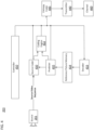
- FIG 2 illustrates, as an example for an application for the disclosed subject matter, the placement of a video encoder and decoder in a streaming environment.
- the disclosed subject matter can be equally applicable to other video enabled applications, including, for example, video conferencing, digital TV, storing of compressed video on digital media including CD, DVD, memory stick and the like, and so on.
- a streaming system (200) may include a capture subsystem (213) that can include a video source (201) and an encoder (203).
- the video source (201) may be, for example, a digital camera, and may be configured to create an uncompressed video sample stream (202).
- the uncompressed video sample stream (202) may provide a high data volume when compared to encoded video bitstreams, and can be processed by the encoder (203) coupled to the camera (201).
- the encoder (203) can include hardware, software, or a combination thereof to enable or implement aspects of the disclosed subject matter as described in more detail below.
- the encoded video bitstream (204) may include a lower data volume when compared to the sample stream, and can be stored on a streaming server (205) for future use.
- One or more streaming clients (206) can access the streaming server (205) to retrieve video bit streams (209) that may be copies of the encoded video bitstream (204).
- the streaming server (205) may also function as a Media-Aware Network Element (MANE).
- the streaming server (205) may be configured to prune the encoded video bitstream (204) for tailoring potentially different bitstreams to one or more of the streaming clients (206).
- a MANE may be separately provided from the streaming server (205) in the streaming system (200).
- the streaming clients (206) can include a video decoder (210) and a display (212).
- the video decoder (210) can, for example, decode video bitstream (209), which is an incoming copy of the encoded video bitstream (204), and create an outgoing video sample stream (211) that can be rendered on the display (212) or another rendering device (not depicted).
- the video bitstreams (204, 209) can be encoded according to certain video coding/compression standards. Examples of such standards include, but are not limited to, ITU-T Recommendation H.265.
- VVC Versatile Video Coding
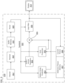
- FIG. 3 illustrates an example functional block diagram of a video decoder (210) that is attached to a display (212) according to an embodiment of the present disclosure.
- the video decoder (210) may include a channel (312), receiver (310), a buffer memory (315), an entropy decoder/parser (320), a scaler/inverse transform unit (351), an intra prediction unit (352), a Motion Compensation Prediction unit (353), an aggregator (355), a loop filter unit (356), reference picture memory (357), and current picture memory ().
- the video decoder (210) may include an integrated circuit, a series of integrated circuits, and/or other electronic circuitry.
- the video decoder (210) may also be partially or entirely embodied in software running on one or more CPUs with associated memories.
- the receiver (310) may receive one or more coded video sequences to be decoded by the decoder (210) one coded video sequence at a time, where the decoding of each coded video sequence is independent from other coded video sequences.
- the coded video sequence may be received from the channel (312), which may be a hardware/software link to a storage device which stores the encoded video data.
- the receiver (310) may receive the encoded video data with other data, for example, coded audio data and/or ancillary data streams, that may be forwarded to their respective using entities (not depicted).
- the receiver (310) may separate the coded video sequence from the other data.
- the buffer memory (315) may be coupled in between the receiver (310) and the entropy decoder/parser (320) ("parser” henceforth).
- the buffer (315) may not be used, or can be small.
- the buffer (315) may be required, can be comparatively large, and can be of adaptive size.
- the video decoder (210) may include a parser (320) to reconstruct symbols (321) from the entropy coded video sequence. Categories of those symbols include, for example, information used to manage operation of the decoder (210), and potentially information to control a rendering device such as a display (212) that may be coupled to a decoder as illustrated in Fig. 2 .
- the control information for the rendering device(s) may be in the form of, for example, Supplementary Enhancement Information (SEI) messages or Video Usability Information (VUI) parameter set fragments (not depicted).
- SEI Supplementary Enhancement Information
- VUI Video Usability Information
- the parser (320) may parse/entropy-decode the coded video sequence received.
- the coding of the coded video sequence can be in accordance with a video coding technology or standard, and can follow principles well known to a person skilled in the art, including variable length coding, Huffman coding, arithmetic coding with or without context sensitivity, and so forth.
- the parser (320) may extract from the coded video sequence, a set of subgroup parameters for at least one of the subgroups of pixels in the video decoder, based upon at least one parameters corresponding to the group. Subgroups can include Groups of Pictures (GOPs), pictures, tiles, slices, macroblocks, Coding Units (CUs), blocks, Transform Units (TUs), Prediction Units (PUs) and so forth.
- the parser (320) may also extract from the coded video sequence information such as transform coefficients, quantizer parameter values, motion vectors, and so forth.
- the parser (320) may perform entropy decoding/parsing operation on the video sequence received from the buffer (315), so to create symbols (321).
- Reconstruction of the symbols (321) can involve multiple different units depending on the type of the coded video picture or parts thereof (such as: inter and intra picture, inter and intra block), and other factors. Which units are involved, and how they are involved, can be controlled by the subgroup control information that was parsed from the coded video sequence by the parser (320). The flow of such subgroup control information between the parser (320) and the multiple units below is not depicted for clarity.
- decoder 210 can be conceptually subdivided into a number of functional units as described below. In a practical implementation operating under commercial constraints, many of these units interact closely with each other and can, at least partly, be integrated into each other. However, for the purpose of describing the disclosed subject matter, the conceptual subdivision into the functional units below is appropriate.
- the scaler/inverse transform unit (351) may receive quantized transform coefficient as well as control information, including which transform to use, block size, quantization factor, quantization scaling matrices, etc. as symbol(s) (321) from the parser (320).
- the scaler/inverse transform unit (351) can output blocks comprising sample values that can be input into the aggregator (355).
- the output samples of the scaler/inverse transform (351) can pertain to an intra coded block; that is: a block that is not using predictive information from previously reconstructed pictures, but can use predictive information from previously reconstructed parts of the current picture.
- Such predictive information can be provided by an intra picture prediction unit (352).
- the intra picture prediction unit (352) generates a block of the same size and shape of the block under reconstruction, using surrounding already reconstructed information fetched from the current (partly reconstructed) picture from the current picture memory (358).
- the aggregator (355) adds, on a per sample basis, the prediction information the intra prediction unit (352) has generated to the output sample information as provided by the scaler/inverse transform unit (351).
- the output samples of the scaler/inverse transform unit (351) can pertain to an inter coded, and potentially motion compensated block.
- a Motion Compensation Prediction unit (353) can access reference picture memory (357) to fetch samples used for prediction. After motion compensating the fetched samples in accordance with the symbols (321) pertaining to the block, these samples can be added by the aggregator (355) to the output of the scaler/inverse transform unit (351) (in this case called the residual samples or residual signal) so to generate output sample information.
- the addresses within the reference picture memory (357), from which the Motion Compensation Prediction unit (353) fetches prediction samples, can be controlled by motion vectors.
- the motion vectors may be available to the Motion Compensation Prediction unit (353) in the form of symbols (321) that can have, for example, X, Y, and reference picture components. Motion compensation also can include interpolation of sample values as fetched from the reference picture memory (357) when sub-sample exact motion vectors are in use, motion vector prediction mechanisms, and so forth.
- Video compression technologies can include in-loop filter technologies that are controlled by parameters included in the coded video bitstream and made available to the loop filter unit (356) as symbols (321) from the parser (320), but can also be responsive to meta-information obtained during the decoding of previous (in decoding order) parts of the coded picture or coded video sequence, as well as responsive to previously reconstructed and loop-filtered sample values.
- the output of the loop filter unit (356) can be a sample stream that can be output to a render device such as a display (212), as well as stored in the reference picture memory (357) for use in future inter-picture prediction.
- coded pictures once fully reconstructed, can be used as reference pictures for future prediction. Once a coded picture is fully reconstructed and the coded picture has been identified as a reference picture (by, for example, parser (320)), the current reference picture can become part of the reference picture memory (357), and a fresh current picture memory can be reallocated before commencing the reconstruction of the following coded picture.
- the video decoder (210) may perform decoding operations according to a predetermined video compression technology that may be documented in a standard, such as ITU-T Rec. H.265.
- the coded video sequence may conform to a syntax specified by the video compression technology or standard being used, in the sense that it adheres to the syntax of the video compression technology or standard, as specified in the video compression technology document or standard and specifically in the profiles document therein.
- the complexity of the coded video sequence may be within bounds as defined by the level of the video compression technology or standard. In some cases, levels restrict the maximum picture size, maximum frame rate, maximum reconstruction sample rate (measured in, for example megasamples per second), maximum reference picture size, and so on. Limits set by levels can, in some cases, be further restricted through Hypothetical Reference Decoder (HRD) specifications and metadata for HRD buffer management signaled in the coded video sequence.
- HRD Hypothetical Reference Decoder
- the receiver (310) may receive additional (redundant) data with the encoded video.
- the additional data may be included as part of the coded video sequence(s).
- the additional data may be used by the video decoder (210) to properly decode the data and/or to more accurately reconstruct the original video data.
- Additional data can be in the form of, for example, temporal, spatial, or SNR enhancement layers, redundant slices, redundant pictures, forward error correction codes, and so on.
- FIG. 4 illustrates an example functional block diagram of a video encoder (203) associated with a video source (201) according to an embodiment of the present disclosure.
- the video encoder (203) may include, for example, an encoder that is a source coder (430), a coding engine (432), a (local) decoder (433), a reference picture memory (434), a predictor (435), a transmitter (440), an entropy coder (445), a controller (450), and a channel (460).
- an encoder that is a source coder (430), a coding engine (432), a (local) decoder (433), a reference picture memory (434), a predictor (435), a transmitter (440), an entropy coder (445), a controller (450), and a channel (460).
- the encoder (203) may receive video samples from a video source (201) (that is not part of the encoder) that may capture video image(s) to be coded by the encoder (203).
- the video source (201) may provide the source video sequence to be coded by the encoder (203) in the form of a digital video sample stream that can be of any suitable bit depth (for example: 8 bit, 10 bit, 12 bit, ...), any colorspace (for example, BT.601 Y CrCB, RGB, ...) and any suitable sampling structure (for example Y CrCb 4:2:0, Y CrCb 4:4:4).
- the video source (201) may be a storage device storing previously prepared video.
- the video source (203) may be a camera that captures local image information as a video sequence.
- Video data may be provided as a plurality of individual pictures that impart motion when viewed in sequence. The pictures themselves may be organized as a spatial array of pixels, wherein each pixel can comprise one or more sample depending on the sampling structure, color space, etc. in use.
- a person skilled in the art can readily understand the relationship between pixels and samples. The description below focuses on samples.
- the encoder (203) may code and compress the pictures of the source video sequence into a coded video sequence (443) in real time or under any other time constraints as required by the application. Enforcing appropriate coding speed is one function of controller (450).
- the controller (450) may also control other functional units as described below and may be functionally coupled to these units. The coupling is not depicted for clarity. Parameters set by the controller (450) can include rate control related parameters (picture skip, quantizer, lambda value of rate-distortion optimization techniques, ...), picture size, group of pictures (GOP) layout, maximum motion vector search range, and so forth.
- rate control related parameters picture skip, quantizer, lambda value of rate-distortion optimization techniques, ...), picture size, group of pictures (GOP) layout, maximum motion vector search range, and so forth.
- a person skilled in the art can readily identify other functions of controller (450) as they may pertain to video encoder (203) optimized for a certain system design.
- a coding loop can consist of the encoding part of the source coder (430) (responsible for creating symbols based on an input picture to be coded, and a reference picture(s)), and the (local) decoder (433) embedded in the encoder (203) that reconstructs the symbols to create the sample data that a (remote) decoder also would create when a compression between symbols and coded video bitstream is lossless in certain video compression technologies. That reconstructed sample stream may be input to the reference picture memory (434).
- the operation of the "local" decoder (433) can be the same as of a "remote” decoder (210), which has already been described in detail above in conjunction with FIG. 3 .
- the entropy decoding parts of decoder (210), including channel (312), receiver (310), buffer (315), and parser (320) may not be fully implemented in the local decoder (433).
- the source coder (430) may perform motion compensated predictive coding, which codes an input frame predictively with reference to one or more previously-coded frames from the video sequence that were designated as "reference frames.”
- the coding engine (432) codes differences between pixel blocks of an input frame and pixel blocks of reference frame(s) that may be selected as prediction reference(s) to the input frame.
- the local video decoder (433) may decode coded video data of frames that may be designated as reference frames, based on symbols created by the source coder (430). Operations of the coding engine (432) may advantageously be lossy processes.
- the coded video data may be decoded at a video decoder (not shown in FIG. 4 )
- the reconstructed video sequence typically may be a replica of the source video sequence with some errors.
- the local video decoder (433) replicates decoding processes that may be performed by the video decoder on reference frames and may cause reconstructed reference frames to be stored in the reference picture memory (434). In this manner, the encoder (203) may store copies of reconstructed reference frames locally that have common content as the reconstructed reference frames that will be obtained by a far-end video decoder (absent transmission errors).
- the controller (450) may manage coding operations of the video coder (430), including, for example, setting of parameters and subgroup parameters used for encoding the video data.
- An Intra Picture may be one that may be coded and decoded without using any other frame in the sequence as a source of prediction.
- Some video codecs allow for different types of Intra pictures, including, for example Independent Decoder Refresh (IDR) Pictures.
- IDR Independent Decoder Refresh
- a Predictive picture may be one that may be coded and decoded using intra prediction or inter prediction using at most one motion vector and reference index to predict the sample values of each block.
- a Bi-directionally Predictive Picture may be one that may be coded and decoded using intra prediction or inter prediction using at most two motion vectors and reference indices to predict the sample values of each block.
- multiple-predictive pictures can use more than two reference pictures and associated metadata for the reconstruction of a single block.
- Source pictures commonly may be subdivided spatially into a plurality of sample blocks (for example, blocks of 4x4, 8x8, 4x8, or 16x16 samples each) and coded on a block-by- block basis.
- Blocks may be coded predictively with reference to other (already coded) blocks as determined by the coding assignment applied to the blocks' respective pictures.
- blocks of I pictures may be coded non-predictively or they may be coded predictively with reference to already coded blocks of the same picture (spatial prediction or intra prediction).
- Pixel blocks of P pictures may be coded non-predictively, via spatial prediction or via temporal prediction with reference to one previously coded reference pictures.
- Blocks of B pictures may be coded non-predictively, via spatial prediction or via temporal prediction with reference to one or two previously coded reference pictures.
- the transmitter (440) may transmit additional data with the encoded video.
- the video coder (430) may include such data as part of the coded video sequence. Additional data may comprise temporal/spatial/SNR enhancement layers, other forms of redundant data such as redundant pictures and slices, Supplementary Enhancement Information (SEI) messages, Visual Usability Information (VUI) parameter set fragments, and so on.
- SEI Supplementary Enhancement Information
- VUI Visual Usability Information
- Sub-Picture henceforth refers to, in some cases, a rectangular arrangement of samples, blocks, macroblocks, coding units, or similar entities that are semantically grouped, and that may be independently coded in changed resolution.
- One or more sub-pictures may form a picture.
- One or more coded sub-pictures may form a coded picture.
- One or more sub-pictures may be assembled into a picture, and one or more sub pictures may be extracted from a picture.
- one or more coded sub-pictures may be assembled in the compressed domain without transcoding to the sample level into a coded picture, and in the same or certain other cases, one or more coded sub-pictures may be extracted from a coded picture in the compressed domain.
- Adaptive Resolution Change henceforth refers to mechanisms that allow the change of resolution of a picture or sub-picture within a coded video sequence, by the means of, for example, reference picture resampling.
- ARC parameters henceforth refer to the control information required to perform adaptive resolution change, that may include, for example, filter parameters, scaling factors, resolutions of output and/or reference pictures, various control flags, and so forth.
- FIGS. 6A-C shown are several novel example embodiments for signaling ARC parameters. As noted with each of the embodiments, they have certain advantages from a coding efficiency, complexity, and architecture viewpoint.
- a video coding standard or technology may implement one or more of these embodiments, and may also include embodiments known from comparative art, for signaling ARC parameters.
- Comparative art embodiments include the examples illustrated in FIGS. 5A-B .
- the novel embodiments may not be mutually exclusive, and conceivably may be included in a standard or technology that also includes comparative art embodiments so that either may be used based on application needs, standards technology involved, or encoder's choice.
- Classes of ARC parameters may include: (1) up/downsample factors, separate or combined in X and Y dimension, or (2) up/downsample factors, with an addition of a temporal dimension, indicating constant speed zoom in/out for a given number of pictures. Either of the above two may involve the coding or decoding of one or more syntax elements that may point into a table containing the factor(s). Such syntax elements may be short in length in embodiments.
- Warping coordinates may be in a suitable granularity as described above.
- H.263 Annex P defines one efficient way to code such warping coordinates, but other, potentially more efficient ways could conceivably also be used.
- the variable length reversible, "Huffman"-style coding of warping coordinates of Annex P could be replaced by a suitable length binary coding, where the length of the binary code word could, for example, be derived from a maximum picture size, possibly multiplied by a certain factor and offset by a certain value, so to allow for "warping" outside of the maximum picture size's boundaries.
- up or downsample filter parameters there may be only a single filter for up and/or downsampling. However, in certain cases, it can be advantageous to allow more flexibility in filter design, which may be implemented by signaling of filter parameters. Such parameters may be selected through an index in a list of possible filter designs, the filter may be fully specified (e.g. through a list of filter coefficients using suitable entropy coding techniques), and/or the filter may be implicitly selected through up/downsample ratios which are signaled according to any of the mechanisms mentioned above, and so forth.
- mappings could be devised according to the needs of an application and the capabilities of the up and downscale mechanisms available in a video compression technology or standard.
- the table could be extended to more values. Values may also be represented by entropy coding mechanisms other than Ext-Golomb codes (e.g. using binary coding) that may have certain advantages when the resampling factors were of interest outside the video processing engines (encoder and decoder foremost) themselves, for example by MANEs. It should be noted that, for the (presumably) most common case where no resolution change is required, an Ext-Golomb code can be chosen that is short (e.g. only a single bit as, for example, shown in the second row of TABLE 1) that can have a coding efficiency advantage over using binary codes for the most common case.
- the number of entries in the table may be fully or partially configurable.
- the basic outline of the table may be conveyed in a "high" parameter set such as a sequence or decoder parameter set.
- one or more such tables may be defined in a video coding technology or standard, and may be selected through, for example, a decoder or sequence parameter set.
- ARC information upsample/downsample factor
- Similar considerations may apply to one or a few codewords controlling up/downsample filters.
- Provided below is also a description regarding when comparatively large amounts of data may be required for a filter or other data structures.
- H.263 Annex P includes ARC information (502) in the form of four warping coordinates within a picture header (501), specifically in an H.263 PLUSPTYPE (503) header extension.
- ARC information 502
- Such a design may be sensible when (a) there is a picture header available, and (b) frequent changes of the ARC information are expected.
- the overhead when using H.263-style signaling can be quite high, and scaling factors may not pertain to picture boundaries because picture header can be of transient nature.
- JVCET-M135-v1 includes ARC reference information (505), (an index) located in a picture parameter set (504), that indexes a table (506) including target resolutions that is located inside a sequence parameter set (507).
- ARC reference information (505)
- an index located in a picture parameter set (504)
- the placement of the possible resolution in the table (506) in the sequence parameter set (507) may be justified by using the SPS (507) as an interoperability negotiation point during capability exchange. Resolution can change, within the limits set by the values in the table (506) from picture to picture by referencing the appropriate picture parameter set (504).
- the following embodiments of the present disclosure may convey ARC information in a video bitstream to, for example, a decoder of the present disclosure.
- ARC information in a video bitstream to, for example, a decoder of the present disclosure.
- Each of those embodiments has certain advantages over comparative art described above.
- the embodiments may be simultaneously present in the same video coding technology or standard.
- ARC information (509) such as a resampling (zoom) factor may be present in a header (508) such as, for example, a slice header, GOB header, tile header, or tile group header.
- FIG. 6A illustrates the header (508) as a Tile Group header.
- the ARC information is small, such as a single variable length ue(v) or fixed length codeword of a few bits, for example as shown in TABLE 1.
- Having the ARC information directly in a tile group header has the additional advantage that the ARC information may be applicable to a sub picture represented by, for example, the tile group corresponding to the tile group header, rather than the whole picture.
- a tile group header e.g. into an H.263-style picture header
- the above description describes the ARC information (509) being present in a tile group header, it will be understood that the above description may also similarly apply in cases where the ARC information (509) is present in, for example, a slice header, GOB header, or tile header.
- ARC information (512) itself may be present in an appropriate parameter set (511) such as, for example, a picture parameter set, header parameter set, tile parameter set, adaptation parameter set, and so forth.
- FIG. 6B illustrates the parameter set (511) as an adaptation parameter set (APS).
- the scope of that parameter set can advantageously be no larger than a picture.
- the scope of the parameter set may be a tile group.
- the use of the ARC information (512) may be implicit through the activation of the relevant parameter set. For example, when a video coding technology or standard contemplates only picture-based ARC, then a picture parameter set or equivalent may be appropriate as the relevant parameter set.
- ARC reference information (513) may be present in a Tile Group header (514) or a similar data structure.
- the ARC reference information (513) can refer to a subset of ARC information (515) available in a parameter set (516) with a scope beyond a single picture.
- the parameter set (516) may be a sequence parameter set (SPS) or a decoder parameter set (DPS).
- a parameter set e.g. an adaptation parameter set or a header parameter set
- an activation scope limited to a tile group may be the better choice.
- the ARC information is of more than negligible size-for example contains filter control information such as numerous filter coefficients-then a parameter may be a better choice than using a header directly from a coding efficiency viewpoint, as those settings may be reusable by future pictures or sub-pictures by referencing the same parameter set.
- FIGS. 7A-B depict syntax diagrams.
- the notation of such syntax diagrams roughly follows C-style programming. Lines in boldface indicate syntax elements present in the bitstream, and lines without boldface often indicate control flow or the setting of variables.
- a tile grouper header can conditionally contain, a variable length, Exp-Golomb coded syntax element dec_pic_size_idx (602) (depicted in boldface).
- dec_pic_size_idx 602
- the presence of this syntax element in the tile group header (600) can be gated by the use of adaptive resolution (603).
- the value of the adaptive resolution flag is not depicted in boldface, which means that the flag is present in the bitstream at the point where it occurs in the syntax diagram.
- adaptive resolution is signaled in any high level syntax structure inside or outside the bitstream.
- adaptive resolution is signaled in a sequence parameter set (610) as outlined below.
- FIG. 7B illustrates an excerpt of the sequence parameter set (610).
- the first syntax element shown is adaptive_pic_resolution_change_flag (611).
- adaptive_pic_resolution_change_flag 631
- such flag can indicate the use of adaptive resolution which, in turn, may require certain control information.
- control information is conditionally present based on the value of the flag based on the if() statement (612) in the sequence parameter set (610) and the tile group header (600).
- coded is an output resolution (613) in units of samples.
- the output resolution (613) in this example embodiment refers to both of syntax elements output_pic_width_in_luma_samples and output_pic_height_in_luma_samples, which together can define the resolution of the output picture.
- certain restrictions to either value can be defined. For example, a level definition may limit the number of total output samples, which could be the product of the value of the above two syntax elements.
- certain video coding technologies or standards, or external technologies or standards such as, for example, system standards, may limit the numbering range (for example, one or both dimensions must be divisible by a power of 2 number), or the aspect ratio (for example, the width and height must be in a relation such as 4:3 or 16:9). Such restrictions may be introduced to facilitate hardware implementations or for other reasons.
- the encoder instructs the decoder to use a certain reference picture size rather than implicitly assume a size to be the output picture size.
- the syntax element reference_pic_size_present_flag (614) gates the conditional presence of reference picture dimensions (615) (again, the numeral refers to both width and height in the example embodiment).
- FIG. 7B further illustrates a table of possible decoding picture width and heights.
- a table can be expressed, for example, by a table indication (616) (e.g. syntax element num_dec_pic_size_in_luma_samples_minus1) .
- the "minus1" of the syntax element can refer to the interpretation of the value of that syntax element. For example, if the coded value of the syntax element is zero, one table entry is present. If the coded value is five, six table entries are present. For each "line" in the table, decoded picture width and height are then included in syntaxes as table entries (617).
- the table entries (617) presented can be indexed using the syntax element dec_pic_size_idx (602) in the tile group header (600), thereby allowing different decoded sizes-in effect, zoom factors-per tile group.
- Certain video coding technologies or standards support spatial scalability by implementing certain forms of reference picture resampling (which may be signaled quite differently from embodiments of the present disclosure) in conjunction with temporal scalability, so to enable spatial scalability.
- certain reference pictures may be upsampled using ARC-style technologies to a higher resolution to form the base of a spatial enhancement layer. Such upsampled pictures could be refined using normal prediction mechanisms at the high resolution so to add detail.
- Embodiments of the disclosure can be used in such an environment.
- a value in the network abstraction layer (NAL) unit header for example the Temporal ID field, can be used to indicate not only the temporal but also the spatial layer. Doing so has certain advantages for certain system designs; for example, existing Selected Forwarding Units (SFU) created and optimized for temporal layer selected forwarding based on the NAL unit header Temporal ID value can be used without modification for scalable environments.
- SFU Selected Forwarding Units
- embodiments of the present disclosure may include a mapping between the coded picture size and the temporal layer to be indicated by the temporal ID field in the NAL unit header.
- an Access Unit can refer to coded picture(s), slice(s), tile(s), NAL Unit(s), and so forth, that were captured and composed into a respective picture/slice/tile/NAL unit bitstream at a given instance in time.
- Such instance in time can be the composition time.
- a picture order count (POC) value can be used for indicating a selected reference picture among multiple reference picture stored in a decoded picture buffer (DPB).
- POC picture order count
- an access unit comprises one or more pictures, slices, or tiles
- each picture, slice, or tile belonging to the same AU may carry the same POC value, from which it can be derived that they were created from content of the same composition time.
- it can be determined that two picture/slice/tile belong to the same AU and have the same composition time in a scenario where the two pictures/slices/tiles carry the same given POC value.
- two pictures/tiles/slices having different POC values can indicate those pictures/slices/tiles belong to different AUs and have different composition times.
- the aforementioned rigid relationship can be relaxed in that an access unit can comprise pictures, slices, or tiles with different POC values.
- an access unit can comprise pictures, slices, or tiles with different POC values.
- the embodiment of the present disclosure can enable support of multiple scalable layers without a change of reference picture selection signaling (e.g. reference picture set signaling or reference picture list signaling), as described in more detail below.
- an access unit count may be signaled in a high-level syntax structure, such as NAL unit header, slice header, tile group header, SEI message, parameter set or AU delimiter.
- the value of AUC may be used to identify which NAL units, pictures, slices, or tiles belong to a given AU.
- the value of AUC may be corresponding to a distinct composition time instance.
- the AUC value may be equal to a multiple of the POC value. By dividing the POC value by an integer value, the AUC value may be calculated. In certain cases, division operations can place a certain burden on decoder implementations. In such cases, small restrictions in the numbering space of the AUC values may allow substitution of the division operation by shift operations performed by embodiments of the present disclosure.
- the AUC value may be equal to a Most Significant Bit (MSB) value of the POC value range.
- MSB Most Significant Bit
- the video bitstream corresponding to a base layer (702) is contained in a track, while the CSPS layers (704) corresponding to each sub-picture are contained in a separated track, in a video file.
- an SPS may be available to the decoding process prior to being referenced by one or more PPS, by being included in at least one PU with nuh_layer_id equal to the lowest nuh_layer_id value of the PPS NAL units that refer to the SPS NAL unit in the CVS, which contains one or more PPS referring to the SPS, or provided through external means.
- variable GeneralLayerIdx[ i ] specifying the layer index of the layer with nuh_layer_id equal to vps_layer_id[ i ] (852), may be derived as follows:
- the syntax element max_tid_il_ref_pics_plus1[ i ] (860) equal to 0 specifies that inter-layer prediction is not used by non-IRAP pictures of the i-th layer.
- the syntax element max_tid_il_ref_pics_plus1[ i ] (860) greater than 0 specifies that, for decoding pictures of the i-th layer, no picture with TemporalId greater than max_tid_il_ref_pics_plus1[ i ] - 1 is used as inter-layer reference picture (ILRP).
- the value of the syntax element max_tid_il_ref_pics_plus1[ i ] (860) may be inferred to be equal to 7.
- the syntax element ols_mode_idc (864) 0 specifies that the total number of OLSs specified by the VPS is equal to vps_max_layers_minus1 + 1, the i-th OLS includes the layers with layer indices from 0 to i, inclusive, and for each OLS only the highest layer in the OLS is output.
- the syntax element ols_mode_idc (864) equal to 1 specifies that the total number of OLSs specified by the VPS is equal to vps_max_layers_minus1 + 1, the i-th OLS includes the layers with layer indices from 0 to i, inclusive, and for each OLS all layers in the OLS are output.
- the syntax element ols_mode_idc (864) equal to 2 specifies that the total number of OLSs specified by the VPS is explicitly signalled and for each OLS the output layers are explicitly signalled and other layers are the layers that are direct or indirect reference layers of the output layers of the OLS.
- the value of the syntax element ols_mode_idc (864) may be in the range of 0 to 2, inclusive.
- the value 3 of the syntax element ols_mode_idc (864) may be reserved for future use by ITU-T
- syntax element num_output_layer_sets_minus1 (866) plus 1 specifies the total number of OLSs specified by the VPS when the syntax element ols_mode_idc (864) is equal to 2.
- the variable TotalNumOlss specifying the total number of OLSs specified by the VPS, may be derived as follows:
- the syntax element ols_output_layer_flag[ i ][ j ](868) equal to 1 specifies that the layer with nuh_layer_id equal to vps_layer_id[ j ] is an output layer of the i-th OLS when ols_mode_idc (864) is equal to 2.
- the syntax element ols_output_layer_flag[ i ][ j ] (868) equal to 0 specifies that the layer with nuh_layer_id equal to vps_layer_id[ j ] is not an output layer of the i-th OLS when the syntax element ols_mode_idc (864) is equal to 2.
- the variable NumOutputLayersInOls[ i ], specifying the number of output layers in the i-th OLS, the variable NumSubLayersInLayerInOLS[ i ][ j ], specifying the number of sublayers in the j-th layer in the i-th OLS, the variable OutputLayerIdInOls[ i ][ j ], specifying the nuh_layer_id value of the j-th output layer in the i-th OLS, and the variable LayerUsedAsOutputLayerFlag[ k ], specifying whether the k-th layer is used as an output layer in at least one OLS, may be derived as follows:
- the values of LayerUsedAsRefLayerFlag[ i ] and LayerUsedAsOutputLayerFlag[ i ] may not be both equal to 0. In other words, there may be no layer that is neither an output layer of at least one OLS nor a direct reference layer of any other layer.
- each OLS there may be at least one layer that is an output layer.
- the value of NumOutputLayersInOls[ i ] may be greater than or equal to 1.
- variable NumLayersInOls[ i ] specifying the number of layers in the i-th OLS
- LayerIdInOls[ i ][ j ] specifying the nuh_layer_id value of the j-th layer in the i-th OLS
- the variable OlsLayerIdx[ i ][ j ], specifying the OLS layer index of the layer with nuh_layer_id equal to LayerIdInOls[ i ][ j ], is derived as follows:
- the lowest layer in each OLS may be an independent layer.
- the value of vps_independent_layer_flag[ GeneralLayerIdx[ LayerIdInOls[ i ][ 0 ] ] ] may be equal to 1.
- Each layer may be included in at least one OLS specified by the VPS.
- nuhLayerId equal to one of vps_layer_id[ k ] for k in the range of 0 to vps_max_layers _minus1, inclusive
- there may be at least one pair of values of i and j where i is in the range of 0 to TotalNumOlss - 1, inclusive, and j is in the range of NumLayersInOls[ i ] - 1, inclusive, such that the value of LayerIdInOls[ i ][ j ] is equal to nuhLayerId.
- a decoding process may operate as follows for a current picture (e.g. sytax element CurrPic) to set the syntax element PictureOutputFlag:
- PictureOutputFlag is set equal to 0 if one of the following conditions is true:
- the syntax element PictureOutputFlag may be set equal to the syntax element pic_output_flag.
- the current decoded picture may be marked as "used for short-term reference", and each ILRP entry in RefPicList[ 0 ] or RefPicList[ 1 ] may be marked as "used for short-term reference”.
- the syntax element PictureOutputFlag is set equal to pic_output_flag, regardless of the value of the syntax element ols_mode_idc (864).
- the syntax element PictureOutputFlag is set equal to 0 when sps_video_parameter_set_id is greater than 0, each_layer_is_an_ols_flag (862) is equal to 0, ols_mode_idc (864) is equal to 0, and the current AU contains a picture picA that satisfies all of the following conditions: PicA has PictureOutputFlag equal to 1, PicA has nuh_layer_id nuhLid greater than that of the current picture, and PicA belongs to the output layer of the OLS (i.e. OutputLayerIdInOls[ TargetOlsIdx ][ 0 ] is equal to nuhLid).
- PictureOutputFlag is set equal to 0 when sps_video_parameter_set_id is greater than 0, each_layer_is_an_ols_flag is equal to 0, ols_mode_idc is equal to 2, and ols_output_layer_flag[ TargetOlsIdx ][ GeneralLayerIdx[ nuh_layer_id ] ] is equal to 0.
- An intra random access point (IRAP) picture may be a coded picture for random access, which may be an instantaneous decoding refresh (IDR) picture that supports closed group of picture structures or a clean random access (CRA) picture that supports open group of picture structure.
- IDR instantaneous decoding refresh
- CRA clean random access
- a gradual decoding refresh (GDR) picture may be a picture for gradual random access with partial refresh of the picture.
- Embodiments of the present disclosure may include syntax elements that indicate an IRAP or GDR picture.
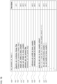
- a picture header (1) may be provided.
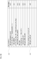
- a flag ph_gdr_or_irap_pic_flag (2) may be signaled. The flag indicates the presence of an IRAP or GDR picture in the current PU associated with the picture header (1).
- a flag ph_no_output_of_prior_pics_flag (3) may be conditionally signaled, only when ph_gdr_or_irap_pic_flag (2) is equal to 1, as shown in FIG. 26 .
- the value of ph_no_output_of_prior_pics_flag (3) may be used for the output and removal process of pictures from the DPB.
- the value of the flag may affect the output of previously-decoded pictures in the DPB after the decoding of a picture in a CVSS AU that is not the first AU in the bitstream.
- an IRAP picture may have ph_gdr_or_irap_pic_flag equal to 0, because the constraint specified by the semantics of ph_gdr_or_irap_pic_flag may be "one way", as follows:
- the flag ph_gdr_or_irap_pic_flag 1 specifies that the current picture is a GDR or IRAP picture.
- the flag ph_gdr_or_irap_pic_flag 0 specifies that the current picture is not a GDR picture and may or may not be an IRAP picture.
- the value of ph_gdr_or _irap_pic_flag of an IRAP picture is equal to 0, the value of ph_no_output_of_prior_pics_flag may be used for DPB operations, without signaling or any inference rule.
- the constraints of the semantics of ph_gdr_or_irap_pic_flag (2) may be specified as "two way", so that ph_no_output_of_prior_pics_flag (3) may be required to be signaled when the current picture is an IRAP picture, as follows:
- the flag ph_gdr_or_irap_pic_flag (2) equal to 1 specifies that the current picture is a GDR or IRAP picture.
- the flag ph_gdr_or_irap_pic_flag (2) equal to 0 specifies that the current picture is neither a GDR or IRAP picture.
- the inference rule of the ph_no_output_of_prior_pics_flag (3) value when not present, may be specified as follows:
- the flag ph_no_output_of_prior_pics_flag (3) affects the output of previously-decoded pictures in the DPB after the decoding of a picture in a CVSS AU that is not the first AU in the bitstream. It may be a requirement of bitstream conformance that, when present, the value of ph_no_output_of_prior_pics_flag (3) shall be the same for all pictures in an AU.
- the ph_no_output_of_prior_pics_flag (3) value of the AU is the ph_no_output_of_prior_pics_flag (3) value of the pictures in the AU.
- the value of ph_no_output_of_prior_pics_flag (3) may be inferred to be equal to 0.
- an AU delimiter (10) may be used to indicate the start of an AU, whether the AU is an IRAP or GDR AU, and the type of slices present in the coded pictures in the AU containing the AU delimiter NAL unit.
- the bitstream contains only one layer, there may not be a normative decoding process associated with the AU delimiter (10).
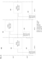
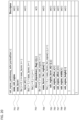
- aud_irap_or_gdr_au_flag (12) may indicate the presence of an IRAP or GDR AU, and may be signaled as shown in FIG. 27 .
- the flag aud_irap_or_gdr_au_flag (12) equal to 1 may specify that the AU containing the AU delimiter is an IRAP or GDR AU.
- the flag aud_irap_or_gdr_au_flag (12) equal to 0 may specify that the AU containing the AU delimiter (10) is neither an IRAP or GDR AU.
- the flag aud_irap_or_gdr_au_flag (12) of an IRAP or GDR AU may be present, when the bitstream has multiple layers, with sps video_parameter set id is greater than 0.
- a video coding technology or standard may mandate the presence of an AU delimiter for a multiple layered bitstream.
- aud_irap_or_gdr_au_flag (12) when aud_irap_or_gdr_au_flag (12) is present and the value of aud_irap_or_gdr_au_flag (12) is equal to 1, the value of ph_gdr_or_irap_pic_flag (2) may be required to be equal to 1. It is because each PU may have a GDR or IRAP picture, when aud_irap_or_gdr_au_flag (12) in AU delimiter (10) is equal to 1.
- pps_mixed_nalu_types_in_pic_flag when pps_mixed_nalu_types_in_pic_flag is equal to 1, the value of ph_no_output_of_prior_pics_flag may not be present.
- pps_mixed_nalu_types_in_pic_flag is determined (e.g. by a decoder) to be present, the value of ph_no_output_of_prior_pics_flag (3) may be ignored.
- ph_no_output_of_prior_pics_flag (3) may affect the output of previously-decoded pictures in the DPB after the decoding of a picture in a CVSS AU that is not the first AU in the bitstream.
- the value of ph_no_output_of_prior_pics_flag (3) may be inferred to be equal 1.
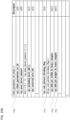
- ph_no_output_of_prior_pics_flag (3) when ph_no_output_of_prior_pics_flag (3) is not present and ph_gdr_or_irap_pic_flag (2) is equal to 1, ph_gdr_or_irap_pic_flag (2) may be replaced in picture header (1) with ph_irap_pic_flag (6), as shown in FIG. 28 .
- the flag ph_irap_pic_flag (6) equal to 1 may specify that the current picture is an IRAP picture.
- the flag ph_irap_pic_flag (6) equal to 0 may specify that the current picture is not an IRAP picture.
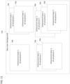
- ph_no_output_of_prior_pics_flag (3) when ph_no_output_of_prior_pics_flag (3) is not present and ph_gdr_or_irap_pic_flag (2) is equal to 1, ph_no_output_of_prior_pics_flag (3) in picture header (1) may be replaced by sh_no_output_of_prior_pics_flag (23) in slice header (20), as shown in FIG. 29 .
- sh_no_output_of_prior_pics_flag (23) may be conditionally present in slice header (20) only when the NAL unit type of the current VCL NAL is equal to IDR_W_RADL, IDR_N_LP, or CRA_NUT.
- IDR_W_RADL is an NAL unit type that contains a coded slice segment of an IDR picture that does not have associated RASL pictures present in the bitstream, but may have associated RADL pictures in the bitstream.
- IDR_N_LP may be an NAL unit type that contains a coded slice segment of an IDR picture that does not have associated leading pictures present in the bitstream.
- CRA_NUT is an NAL unit type that contains a coded slice segment of a CRA picture.
- sh_no_output_of_prior_pics_flag (23) may affect the output of previously-decoded pictures in the DPB after the decoding of a picture in a CVSS AU that is not the first AU in the bitstream.
- sh_no_output_of_prior_pics_flag (23) may be the same for all pictures in an AU.
- sh_no_output_of_prior_pics_flag (23) value of the AU may be the sh_no_output_of_prior_pics_flag (23) value of the pictures in the AU.
- aud_irap_au_flag (16) may be present in AU delimiter (10), as shown in FIG. 30 .
- the flag aud_irap_au_flag (16) equal to 1 may specify that the AU containing the AU delimiter (10) is an IRAP AU.
- the flag aud_irap_au_flag (16) equal to 0 may specify that the AU containing the AU delimiter (10) is not an IRAP AU.
- the value of ph_irap_pic_flag (6) in picture header (1) may be equal to aud_irap_au_flag (16) in AU delimiter (10).
- the flag ph_irap_pic_flag (7) equal to 1 may specify that picture associated with PH (1) is an IRAP picture.
- the flag ph_irap_pic_flag (6) equal to 0 may specify that picture associated with PH (1) is not an IRAP picture.
- aud_gdr_au_flag (17) may be present in AU delimiter (10), as shown in FIG. 30 .
- the flag aud_gdr_au_flag (17) equal to 1 may specify that the AU containing the AU delimiter (10) is a GDR AU.
- the flag aud_irap_au_flag (17) equal to 0 may specify that the AU containing the AU delimiter (10) is not a GDR AU.
- the value of ph_gdr_pic_flag (7) in picture header (1) may be equal to aud_gdr_au_flag (17) in AU delimiter (10).
- the flag ph_gdr_pic_flag (7) equal to 1 may specify that the picture associated with PH (1) is a GDR picture.
- the flag ph_gdr_pic_flag (7) equal to 0 may specify that the picture associated with PH (1) is not a GDR picture.
- GDR Gradual decoding refresh
- the first picture in the bitstream in decoding order may be an IRAP or GDR picture. Trailing pictures associated with an IRAP or GDR picture may also follow the IRAP or GDR picture in decoding order. Pictures that follow the associated IRAP picture in output order and precede the associated IRAP picture in decoding order may not be allowed.
- syntax elements indicating GDR are signaled in PH (1) such as ph_gdr_pic_flag (7).
- the value of ph_gdr_pic_flag (7) may be inferred to be equal to 0.
- sps_gdr enabled_flag is equal to 0
- the value of ph_gdr_pic_flag (7) may be inferred to be equal to 0.
- the syntax element ph_recovery_poc_cnt (32) may specify the recovery point of decoded pictures in output order.
- variable recoveryPointPocVal PicOrderCntVal + ph_recovery_poc_cnt
- the picture picA may be referred to as the recovery point picture. Otherwise, the first picture in output order that has PicOrderCntVal greater than recoveryPointPocVal in the CLVS may be referred to as the recovery point picture.
- the recovery point picture may not precede the current GDR picture in decoding order.
- the pictures that are associated with the current GDR picture and have PicOrderCntVal less than recoveryPointPocVal may be referred to as the recovering pictures of the GDR picture.
- the value of ph_recovery_poc_cnt (34) may be in the range of 0 to MaxPicOrderCntLsb - 1, inclusive.
- the recovery point picture may not precede the current GDR picture in both decoding and output order.
- the recovering picture may not precede the current GDR picture in both decoding and output order.
- the recovering picture may precede the associated recovery point picture in both decoding and output order.
- the current picture when the current picture is a GDR picture or a recovering picture of a GDR picture, and the current picture contains a non-CTU-aligned boundary between a "refreshed area” (i.e. an area that has an exact match of decoded sample values when starting the decoding process from the GDR picture compared to starting the decoding process from the previous IRAP picture in decoding order, when present) and a "dirty area" (i.e.
- chroma residual scaling of luma mapping with chroma scaling may have to be disabled in the current picture to avoid the "dirty area" to affect decoded sample values of the "refreshed area”.
- the value of recoveryPointPocVal of a layer A may be equal to or greater than recoveryPointPocVal of the reference layer of the layer A.
- the value of recoveryPointPocVal of a layer A with layerId equal to m may be equal to or greater than recoveryPointPocVal of another layer B with layerId equal to n, where m is greater than n.
- the value of recoveryPointPocVal of a layer A with layerId equal to m may be equal to or greater than recoveryPointPocVal of another layer B with layerId equal to n, where m is greater than n and the layers A and B belong the same output layer set.
- the value of recoveryPointPocVal of a layer A may be equal to recoveryPointPocVal of the reference layer of the layer A.
- the value of recoveryPointPocVal of a layer A with layerId equal to m may be equal to recoveryPointPocVal of another layer B with layerId equal to n, where m is greater than n.
- the value of recoveryPointPocVal of a layer A with layerId equal to m may be equal to recoveryPointPocVal of another layer B with layerId equal to n, where m is greater than n and the layers A and B belong the same output layer set.
- TRAIL_NUT is an NAL unit type that contains a coded tile group of VCL non-STSA trailing picture.
- the decoding process for reference picture lists construction may be invoked for derivation of reference picture list 0 (RefPicList[ 0 ]) and reference picture list 1 (RefPicList[ 1 ]).
- the decoding process for reference picture marking may be invoked, wherein reference pictures may be marked as "unused for reference”, “used for short-term reference”, or "used for long-term reference”.
- a decoding process (40) may be performed by a decoder.
- one or more reference picture lists (RPLs) may be constructed (42).
- RPLs reference picture lists
- the decoder may determine whether a reference picture in the RPL is available in the DPB (44). If the reference picture is determined to be unavailable, the unavailable reference pictures may be marked as "no reference picture". To avoid any decoder crash or unintended behavior, the unavailable reference pictures may be instantly generated with defaults values of pixels and parameters (46). After generating the unavailable reference pictures (and/or the reference pictures are determined to be available), the decoder may check the validation of all reference pictures, including the generated pictures, in the reference picture list (48).
- the one or more reference picture lists are constructed (42) by parsing the RPL syntax elements in SPS, PH, and/or SH. After the constructing (42), one or more reference pictures in RPL list may not be available because the random access skipped leading pictures (RASL) associated with a CRA picture may be discarded by a decoder or a system or cannot be successfully decoded when random access happens at the CRA picture.
- the unavailable reference pictures may be generated with defaults values of pixels and parameters (46).
- the current picture is an IDR picture with sps_idr_rpl_present_flag equal to 1 or pps_rpl_info_in_ph_flag equal to 1, a CRA picture with NoOutputBeforeRecoveryFlag equal to 1, or a GDR picture with NoOutputBeforeRecoveryFlag equal to 1, at least one of the following decoding processes for generating unavailable reference pictures (46) is invoked, which may need to be invoked only for the first slice of a picture.
- This process may be invoked once per coded picture when the current picture is an IDR picture with sps_idr_rpl_present_flag equal to 1 or pps_rpl_info_in_ph_flag equal to 1, a CRA picture with NoOutputBeforeRecoveryFlag equal to 1, or a GDR picture with NoOutputBeforeRecoveryFlag equal to 1.
- the flag ph_non_ref_pic_flag 1 may specify that the picture associated with the PH is never used as a reference picture.
- the flag ph_non_ref_pic_flag 0 may specify the picture associated with the PH may or may not be used as a reference picture.
- bitstream conformances check for all or active reference pictures in RPL list may be invoked by, for example, the decoder.
- the decoder may check that the following constraints apply for bitstream conformance:
- the process may be invoked once per picture, after decoding of a slice header and the decoding process for reference picture list construction for the slice, but prior to the decoding of the slice data. This process may result in one or more reference pictures in the DPB being marked as "unused for reference” or "used for long-term reference".
- a decoded picture in the DPB can be marked as "unused for reference”, “used for short-term reference” or “used for long-term reference”, but only one among these three at any given moment during the operation of the decoding process. Assigning one of these markings to a picture may implicitly remove another of these markings when applicable. When a picture is referred to as being marked as “used for reference”, this collectively refers to the picture being marked as “used for short-term reference” or “used for long-term reference” (but not both).
- STRPs and ILRPs may be identified by their nuh_layer_id and PicOrderCntVal values.
- LTRPs may be identified by their nuh_layer_id values and the Log2( MaxLtPicOrderCntLsb ) LSBs of their PicOrderCntVal values.
- all reference pictures currently in the DPB (if any) with the same nuh_layer_id as the current picture may be marked as "unused for reference”.
- each RefPicList[ i ][ j ] with i in the range of 0 to 1, inclusive, and j in the range of 0 to num_ref_entries[ i ][ RplsIdx[ i ] ] - 1, inclusive, that is equal to "no reference picture", a picture is generated.
- missing reference pictures in DPB may be set equal to "no reference picture".
- the unavailable pictures equal to "no reference picture” are generated through the decoding process for generating unavailable reference pictures for conformance check purposes.
- An issue is that not only unavailable reference pictures in the same layer but also unavailable interlayer reference pictures in the reference layer are set equal to "no reference picture", as below:
- all unavailable pictures equal to "no reference picture” may be handled as the reference pictures in the same layer, so that the nuh_layer_id and PicOrderCntVal values of the unavailable interlayer reference pictures are set to incorrrect values. Also, the unavailable interlayer reference pictures are not correctly marked as "used for long-term reference”. These wrong values result in errors in decoding process of the following pictures and bitstream conformance check. Therefore, according to embodiments, the unavailable interlayer reference pictures equal to "no reference picture" should be correctly generated as follows:
- This process is invoked once per coded picture when the current picture is an IDR picture with sps_idr_rpl_present_flag equal to 1 or pps_rpl_info_in_ph_flag equal to 1, a CRA picture with NoOutputBeforeRecoveryFlag equal to 1, or a GDR picture with NoOutputBeforeRecoveryFlag equal to 1.
- a picture may be generated as previously described in the present dislcosure and the following may apply:
- the original sentence is modified as follows: For each LTRP entry in RefPicList[ 0 ] or RefPicList[ 1 ], when the picture is currently marked as "used for short-term reference" with the same nuh_layer_id as the current picture, the picture is marked as "used for long-term reference”.
- the original sentence is modified as follows: For each LTRP entry in RefPicList[ 0 ] or RefPicList[ 1 ], when the picture is is an LTRP with the same nuh_layer_id as the current picture, the picture is marked as "used for long-term reference".
- the reference picture lists are constructed after generating unavailable reference pictures in RPS.
- VVC current draft
- the reference picture lists are constructed before generating unavailable reference pictures in RPS. If the bitstream conformance check is performed before generating unavailable reference pictures as previously specified, the bitstream cannot obey the constraints specified.
- the decoding process may be modified as follows to have the following constraints for bitstream conformance:
- the decoder may check whether the above constraints are met for bitstream conformance.
- the conformance check may be done after invoking decoding process for generating unavailable reference pictures as described above.
- Embodiments of the present disclosure may comprise at least one processor and memory storing computer code.
- the computer code when executed by the at least one processor, may be configured to cause the at least one processor to perform the functions of the embodiments of the present disclosure.
- a decoder of the present disclosure may comprise at least one processor and memory storing computer code (80).
- the decoder may be configured to receive a bitstream including at least one coded picture and parameter sets (e.g., SPS and VPS), headers (e.g. picture headers and slice headers), and AU delimiters.
- the computer code may be configured to cause the at least one processor to perform any number of the decoding processes (e.g. constructing a reference picture list, generating an unavailable reference picture, and checking bitstream conformance) and aspects related to decoding (e.g. signaling of flags and other syntax elements in picture header, slice header, and access unit delimiter) as described in the present disclosure.
- the computer code (80) may include a plurality of signaling code (81) and decoding code (82).
- the plurality of signaling code (81) may include various signaling code that is configured to cause the at least one processor to signal (and/or infer) flags and other syntax elements in picture header, slice header, and access unit delimiter.
- the decoding code (82) may be configured to cause the at least one processor to decode one or more pictures.
- the decoding code (82) may include constructing code (83), generating code (84), and checking code (85).
- the constructing code (83) may be configured to cause the at least one processor to construct a reference picture list(s).
- the generating code (84) may be configured to cause the at least one processor to generate an unavailable reference picture in the reference picture list(s).
- the checking code (85) may be configured to to cause the at least one processor to check bitstream conformance, for references pictures in the reference picture list(s), that the following constraints apply: (a) a number of entries that are indicated to be in the reference picture list is not less than a number of active entries that are indicated to be in the reference picture list, (b) each picture referred to by an active entry in the reference picture list is present in a decoded picture buffer (DPB) and has a temporal identifier value less than or equal to a temporal identifier value of the current picture, and (c) each picture referred to by an entry in the reference picture list is not the current picture and is indicated by a picture header flag to potentially be a reference picture.
- DPB decoded picture buffer
- FIG. 34 shows a computer system (900) suitable for implementing embodiments of the disclosed subject matter.
- the computer software can be coded using any suitable machine code or computer language, that may be subject to assembly, compilation, linking, or like mechanisms to create code comprising instructions that can be executed directly, or through interpretation, micro-code execution, and the like, by computer central processing units (CPUs), Graphics Processing Units (GPUs), and the like.
- CPUs computer central processing units
- GPUs Graphics Processing Units
- the instructions can be executed on various types of computers or components thereof, including, for example, personal computers, tablet computers, servers, smartphones, gaming devices, internet of things devices, and the like.
- FIG. 34 for computer system (900) are exemplary in nature and are not intended to suggest any limitation as to the scope of use or functionality of the computer software implementing embodiments of the present disclosure. Neither should the configuration of components be interpreted as having any dependency or requirement relating to any one or combination of components illustrated in the exemplary embodiment of a computer system (900).
- Computer system (900) may include certain human interface input devices.
- a human interface input device may be responsive to input by one or more human users through, for example, tactile input (such as: keystrokes, swipes, data glove movements), audio input (such as: voice, clapping), visual input (such as: gestures), olfactory input (not depicted).
- the human interface devices can also be used to capture certain media not necessarily directly related to conscious input by a human, such as audio (such as: speech, music, ambient sound), images (such as: scanned images, photographic images obtain from a still image camera), video (such as two-dimensional video, three-dimensional video including stereoscopic video).
- Input human interface devices may include one or more of (only one of each depicted): keyboard (901), mouse (902), trackpad (903), touch screen (910), data-glove , joystick (905), microphone (906), scanner (907), and camera (908).
- Computer system (900) may also include certain human interface output devices.
- Such human interface output devices may be stimulating the senses of one or more human users through, for example, tactile output, sound, light, and smell/taste.
- Such human interface output devices may include tactile output devices (for example tactile feedback by the touch-screen (910), data-glove , or joystick (905), but there can also be tactile feedback devices that do not serve as input devices).
- such devices may be audio output devices (such as: speakers (909), headphones (not depicted)), visual output devices (such as screens (910) to include CRT screens, LCD screens, plasma screens, OLED screens, each with or without touch-screen input capability, each with or without tactile feedback capability-some of which may be capable to output two dimensional visual output or more than three dimensional output through means such as stereographic output; virtual-reality glasses (not depicted), holographic displays and smoke tanks (not depicted)), and printers (not depicted).
- audio output devices such as: speakers (909), headphones (not depicted)
- visual output devices such as screens (910) to include CRT screens, LCD screens, plasma screens, OLED screens, each with or without touch-screen input capability, each with or without tactile feedback capability-some of which may be capable to output two dimensional visual output or more than three dimensional output through means such as stereographic output; virtual-reality glasses (not depicted), holographic displays and smoke tanks (not depicted)), and printers (not depicted).
- Computer system (900) can also include human accessible storage devices and their associated media such as optical media including CD/DVD ROM/RW (920) with CD/DVD or the like media (921), thumb-drive (922), removable hard drive or solid state drive (923), legacy magnetic media such as tape and floppy disc (not depicted), specialized ROM/ASIC/PLD based devices such as security dongles (not depicted), and the like.
- optical media including CD/DVD ROM/RW (920) with CD/DVD or the like media (921), thumb-drive (922), removable hard drive or solid state drive (923), legacy magnetic media such as tape and floppy disc (not depicted), specialized ROM/ASIC/PLD based devices such as security dongles (not depicted), and the like.
- Computer system (900) can also include interface to one or more communication networks.
- Networks can for example be wireless, wireline, optical.
- Networks can further be local, wide-area, metropolitan, vehicular and industrial, real-time, delay-tolerant, and so on.
- Examples of networks include local area networks such as Ethernet, wireless LANs, cellular networks to include GSM, 3G, 4G, 5G, LTE and the like, TV wireline or wireless wide area digital networks to include cable TV, satellite TV, and terrestrial broadcast TV, vehicular and industrial to include CANBus, and so forth.
- Certain networks commonly require external network interface adapters that attached to certain general purpose data ports or peripheral buses (949) (such as, for example USB ports of the computer system (900); others are commonly integrated into the core of the computer system 900 by attachment to a system bus as described below (for example Ethernet interface into a PC computer system or cellular network interface into a smartphone computer system).
- computer system (900) can communicate with other entities.
- Such communication can be uni-directional, receive only (for example, broadcast TV), uni-directional send-only (for example CANbus to certain CANbus devices), or bi-directional, for example to other computer systems using local or wide area digital networks.
- Such communication can include communication to a cloud computing environment (955). Certain protocols and protocol stacks can be used on each of those networks and network interfaces as described above.
- Aforementioned human interface devices, human-accessible storage devices, and network interfaces (954) can be attached to a core (940) of the computer system (900).
- the core (940) can include one or more Central Processing Units (CPU) (941), Graphics Processing Units (GPU) (942), specialized programmable processing units in the form of Field Programmable Gate Areas (FPGA) (943), hardware accelerators (944) for certain tasks , and so forth. These devices, along with Read-only memory (ROM) (945), Random-access memory (946), internal mass storage such as internal non-user accessible hard drives, SSDs, and the like (947), may be connected through a system bus (948). In some computer systems, the system bus (948) can be accessible in the form of one or more physical plugs to enable extensions by additional CPUs, GPU, and the like.
- the peripheral devices can be attached either directly to the core's system bus (948), or through a peripheral bus (949). Architectures for a peripheral bus include PCI, USB, and the like.
- a graphics adapter 950 may be included in the core 940.
- CPUs (941), GPUs (942), FPGAs (943), and accelerators (944) can execute certain instructions that, in combination, can make up the aforementioned computer code. That computer code can be stored in ROM (945) or RAM (946). Transitional data can be also be stored in RAM (946), whereas permanent data can be stored for example, in the internal mass storage (947). Fast storage and retrieve to any of the memory devices can be enabled through the use of cache memory, that can be closely associated with one or more CPU (941), GPU (942), mass storage (947), ROM (945), RAM (946), and the like.
- the computer readable media can have computer code thereon for performing various computer-implemented operations.
- the media and computer code can be those specially designed and constructed for the purposes of the present disclosure, or they can be of the kind well known and available to those having skill in the computer software arts.
- the computer system having architecture (900), and specifically the core (940) can provide functionality as a result of processor(s) (including CPUs, GPUs, FPGA, accelerators, and the like) executing software embodied in one or more tangible, computer-readable media.
- processor(s) including CPUs, GPUs, FPGA, accelerators, and the like
- Such computer-readable media can be media associated with user-accessible mass storage as introduced above, as well as certain storage of the core (940) that are of non-transitory nature, such as core-internal mass storage (947) or ROM (945).
- the software implementing various embodiments of the present disclosure can be stored in such devices and executed by core (940).
- a computer-readable medium can include one or more memory devices or chips, according to particular needs.
- the software can cause the core (940) and specifically the processors therein (including CPU, GPU, FPGA, and the like) to execute particular processes or particular parts of particular processes described herein, including defining data structures stored in RAM (946) and modifying such data structures according to the processes defined by the software.
- the computer system can provide functionality as a result of logic hardwired or otherwise embodied in a circuit (for example: accelerator (944)), which can operate in place of or together with software to execute particular processes or particular parts of particular processes described herein.
- Reference to software can encompass logic, and vice versa, where appropriate.
- Reference to a computer-readable media can encompass a circuit (such as an integrated circuit (IC)) storing software for execution, a circuit embodying logic for execution, or both, where appropriate.
- the present disclosure encompasses any suitable combination of hardware and software.
Landscapes
- Engineering & Computer Science (AREA)
- Multimedia (AREA)
- Signal Processing (AREA)
- Compression Or Coding Systems Of Tv Signals (AREA)
- Compression, Expansion, Code Conversion, And Decoders (AREA)
Applications Claiming Priority (7)
| Application Number | Priority Date | Filing Date | Title |
|---|---|---|---|
| US202063027826P | 2020-05-20 | 2020-05-20 | |
| US202063035274P | 2020-06-05 | 2020-06-05 | |
| US202063036335P | 2020-06-08 | 2020-06-08 | |
| US202063037903P | 2020-06-11 | 2020-06-11 | |
| US17/320,764 US11558630B2 (en) | 2020-05-20 | 2021-05-14 | Techniques for random access point indication and picture output in coded video stream |
| EP21786318.2A EP3942802B1 (de) | 2020-05-20 | 2021-05-18 | Techniken für direktzugriffspunktanzeige und bildausgabe in einem codierten videostrom |
| PCT/US2021/032924 WO2021236610A1 (en) | 2020-05-20 | 2021-05-18 | Techniques for random access point indication and picture output in coded video stream |
Related Parent Applications (2)
| Application Number | Title | Priority Date | Filing Date |
|---|---|---|---|
| EP21786318.2A Division-Into EP3942802B1 (de) | 2020-05-20 | 2021-05-18 | Techniken für direktzugriffspunktanzeige und bildausgabe in einem codierten videostrom |
| EP21786318.2A Division EP3942802B1 (de) | 2020-05-20 | 2021-05-18 | Techniken für direktzugriffspunktanzeige und bildausgabe in einem codierten videostrom |
Publications (2)
| Publication Number | Publication Date |
|---|---|
| EP4521740A2 true EP4521740A2 (de) | 2025-03-12 |
| EP4521740A3 EP4521740A3 (de) | 2025-05-14 |
Family
ID=78611095
Family Applications (2)
| Application Number | Title | Priority Date | Filing Date |
|---|---|---|---|
| EP25153956.5A Pending EP4521740A3 (de) | 2020-05-20 | 2021-05-18 | Verfahren und vorrichtung zur videodecodierung, verfahren und vorrichtung zur videocodierung, verfahren zur speicherung eines videobitstroms und computerlesbares medium |
| EP21786318.2A Active EP3942802B1 (de) | 2020-05-20 | 2021-05-18 | Techniken für direktzugriffspunktanzeige und bildausgabe in einem codierten videostrom |
Family Applications After (1)
| Application Number | Title | Priority Date | Filing Date |
|---|---|---|---|
| EP21786318.2A Active EP3942802B1 (de) | 2020-05-20 | 2021-05-18 | Techniken für direktzugriffspunktanzeige und bildausgabe in einem codierten videostrom |
Country Status (7)
| Country | Link |
|---|---|
| EP (2) | EP4521740A3 (de) |
| JP (5) | JP7536785B2 (de) |
| KR (2) | KR20250039498A (de) |
| CN (3) | CN119211526A (de) |
| AU (3) | AU2021257907B2 (de) |
| CA (1) | CA3136422A1 (de) |
| SG (1) | SG11202111934TA (de) |
Families Citing this family (2)
| Publication number | Priority date | Publication date | Assignee | Title |
|---|---|---|---|---|
| CN121128162A (zh) * | 2023-04-28 | 2025-12-12 | 抖音视界有限公司 | 基于gdr的视频编解码中的时域参考的限制 |
| WO2026034563A1 (ja) * | 2024-08-07 | 2026-02-12 | マクセル株式会社 | 放送受信装置およびコンテンツ保護方法 |
Family Cites Families (3)
| Publication number | Priority date | Publication date | Assignee | Title |
|---|---|---|---|---|
| US10045021B2 (en) | 2013-04-05 | 2018-08-07 | Samsung Electronics Co., Ltd. | Multi-layer video coding method for random access and device therefor, and multi-layer video decoding method for random access and device therefor |
| US9860529B2 (en) * | 2013-07-16 | 2018-01-02 | Qualcomm Incorporated | Processing illumination compensation for video coding |
| KR102610092B1 (ko) | 2018-08-17 | 2023-12-04 | 후아웨이 테크놀러지 컴퍼니 리미티드 | 비디오 코딩의 참조 픽처 관리 |
-
2021
- 2021-05-18 CA CA3136422A patent/CA3136422A1/en active Pending
- 2021-05-18 EP EP25153956.5A patent/EP4521740A3/de active Pending
- 2021-05-18 CN CN202411192579.6A patent/CN119211526A/zh active Pending
- 2021-05-18 JP JP2021562870A patent/JP7536785B2/ja active Active
- 2021-05-18 EP EP21786318.2A patent/EP3942802B1/de active Active
- 2021-05-18 SG SG11202111934TA patent/SG11202111934TA/en unknown
- 2021-05-18 KR KR1020257007559A patent/KR20250039498A/ko active Pending
- 2021-05-18 CN CN202411184894.4A patent/CN119211525A/zh active Pending
- 2021-05-18 KR KR1020217039637A patent/KR102779997B1/ko active Active
- 2021-05-18 CN CN202180002968.6A patent/CN114287132B/zh active Active
- 2021-05-18 AU AU2021257907A patent/AU2021257907B2/en active Active
-
2023
- 2023-07-06 AU AU2023204353A patent/AU2023204353B2/en active Active
- 2023-11-27 JP JP2023199968A patent/JP7633362B2/ja active Active
-
2024
- 2024-08-07 JP JP2024130815A patent/JP7701526B2/ja active Active
-
2025
- 2025-01-03 AU AU2025200032A patent/AU2025200032A1/en active Pending
- 2025-02-06 JP JP2025018399A patent/JP2025065343A/ja active Pending
- 2025-06-19 JP JP2025103942A patent/JP2025126215A/ja active Pending
Non-Patent Citations (2)
| Title |
|---|
| BROSS: "Versatile Video Coding (Draft 9", JOINT VIDEO EXPERTS TEAM DOCUMENT JVET-R2001-VA, April 2020 (2020-04-01) |
| HENDRY: "On adaptive resolution change (ARC) for VVC", JOINT VIDEO TEAM DOCUMENT JVET-M0135-V1, 2019 |
Also Published As
| Publication number | Publication date |
|---|---|
| AU2023204353A1 (en) | 2023-07-27 |
| CN119211526A (zh) | 2024-12-27 |
| JP2022537244A (ja) | 2022-08-25 |
| AU2023204353B2 (en) | 2024-10-03 |
| CN119211525A (zh) | 2024-12-27 |
| EP3942802B1 (de) | 2025-03-05 |
| KR20250039498A (ko) | 2025-03-20 |
| JP2025126215A (ja) | 2025-08-28 |
| JP7701526B2 (ja) | 2025-07-01 |
| EP3942802C0 (de) | 2025-03-05 |
| JP2024152789A (ja) | 2024-10-25 |
| AU2021257907B2 (en) | 2023-04-06 |
| EP3942802A1 (de) | 2022-01-26 |
| KR20220003091A (ko) | 2022-01-07 |
| JP2024009265A (ja) | 2024-01-19 |
| AU2021257907A1 (en) | 2021-12-09 |
| JP2025065343A (ja) | 2025-04-17 |
| SG11202111934TA (en) | 2021-12-30 |
| EP4521740A3 (de) | 2025-05-14 |
| CN114287132A (zh) | 2022-04-05 |
| AU2025200032A1 (en) | 2025-01-23 |
| CA3136422A1 (en) | 2021-11-20 |
| CN114287132B (zh) | 2024-07-23 |
| JP7633362B2 (ja) | 2025-02-19 |
| JP7536785B2 (ja) | 2024-08-20 |
| KR102779997B1 (ko) | 2025-03-12 |
| EP3942802A4 (de) | 2022-10-05 |
Similar Documents
| Publication | Publication Date | Title |
|---|---|---|
| US12382079B2 (en) | Techniques for random access point indication and picture output in coded video stream | |
| US11228776B1 (en) | Method for output layer set mode in multilayered video stream | |
| US20200404269A1 (en) | Method for region-wise scalability with adaptive resolution change | |
| US12309356B2 (en) | Method for output layer set for multilayered video stream | |
| AU2023202725B2 (en) | Method for picture output with output layer set | |
| AU2025200032A1 (en) | Techniques for random access point indication and picture output in coded video stream | |
| EP3939168B1 (de) | Verfahren für modus zur einstellung einer ausgangsschicht |
Legal Events
| Date | Code | Title | Description |
|---|---|---|---|
| PUAI | Public reference made under article 153(3) epc to a published international application that has entered the european phase |
Free format text: ORIGINAL CODE: 0009012 |
|
| STAA | Information on the status of an ep patent application or granted ep patent |
Free format text: STATUS: THE APPLICATION HAS BEEN PUBLISHED |
|
| AC | Divisional application: reference to earlier application |
Ref document number: 3942802 Country of ref document: EP Kind code of ref document: P |
|
| AK | Designated contracting states |
Kind code of ref document: A2 Designated state(s): AL AT BE BG CH CY CZ DE DK EE ES FI FR GB GR HR HU IE IS IT LI LT LU LV MC MK MT NL NO PL PT RO RS SE SI SK SM TR |
|
| RIN1 | Information on inventor provided before grant (corrected) |
Inventor name: LIU, SHAN Inventor name: WENGER, STEPHAN Inventor name: CHOI, BYEONGDOO |
|
| REG | Reference to a national code |
Ref country code: DE Ref legal event code: R079 Free format text: PREVIOUS MAIN CLASS: H04N0019172000 Ipc: H04N0019700000 |
|
| PUAL | Search report despatched |
Free format text: ORIGINAL CODE: 0009013 |
|
| AK | Designated contracting states |
Kind code of ref document: A3 Designated state(s): AL AT BE BG CH CY CZ DE DK EE ES FI FR GB GR HR HU IE IS IT LI LT LU LV MC MK MT NL NO PL PT RO RS SE SI SK SM TR |
|
| RIC1 | Information provided on ipc code assigned before grant |
Ipc: H04N 19/172 20140101ALI20250408BHEP Ipc: H04N 19/105 20140101ALI20250408BHEP Ipc: H04N 19/11 20140101ALI20250408BHEP Ipc: H04N 19/169 20140101ALI20250408BHEP Ipc: H04N 19/159 20140101ALI20250408BHEP Ipc: H04N 19/30 20140101ALI20250408BHEP Ipc: H04N 19/58 20140101ALI20250408BHEP Ipc: H04N 19/597 20140101ALI20250408BHEP Ipc: H04N 19/573 20140101ALI20250408BHEP Ipc: H04N 19/46 20140101ALI20250408BHEP Ipc: H04N 19/70 20140101AFI20250408BHEP |
|
| STAA | Information on the status of an ep patent application or granted ep patent |
Free format text: STATUS: REQUEST FOR EXAMINATION WAS MADE |
|
| 17P | Request for examination filed |
Effective date: 20250620 |