EP4521868A1 - Elektronische vorrichtung - Google Patents
Elektronische vorrichtung Download PDFInfo
- Publication number
- EP4521868A1 EP4521868A1 EP23196089.9A EP23196089A EP4521868A1 EP 4521868 A1 EP4521868 A1 EP 4521868A1 EP 23196089 A EP23196089 A EP 23196089A EP 4521868 A1 EP4521868 A1 EP 4521868A1
- Authority
- EP
- European Patent Office
- Prior art keywords
- channel
- electronic device
- circuit board
- electronic circuit
- airflow
- Prior art date
- Legal status (The legal status is an assumption and is not a legal conclusion. Google has not performed a legal analysis and makes no representation as to the accuracy of the status listed.)
- Pending
Links
Images

Classifications
-
- H—ELECTRICITY
- H05—ELECTRIC TECHNIQUES NOT OTHERWISE PROVIDED FOR
- H05K—PRINTED CIRCUITS; CASINGS OR CONSTRUCTIONAL DETAILS OF ELECTRIC APPARATUS; MANUFACTURE OF ASSEMBLAGES OF ELECTRICAL COMPONENTS
- H05K7/00—Constructional details common to different types of electric apparatus
- H05K7/20—Modifications to facilitate cooling, ventilating, or heating
- H05K7/20009—Modifications to facilitate cooling, ventilating, or heating using a gaseous coolant in electronic enclosures
- H05K7/20136—Forced ventilation, e.g. by fans
- H05K7/20154—Heat dissipaters coupled to components
- H05K7/20163—Heat dissipaters coupled to components the components being isolated from air flow, e.g. hollow heat sinks, wind tunnels or funnels
-
- H—ELECTRICITY
- H05—ELECTRIC TECHNIQUES NOT OTHERWISE PROVIDED FOR
- H05K—PRINTED CIRCUITS; CASINGS OR CONSTRUCTIONAL DETAILS OF ELECTRIC APPARATUS; MANUFACTURE OF ASSEMBLAGES OF ELECTRICAL COMPONENTS
- H05K7/00—Constructional details common to different types of electric apparatus
- H05K7/20—Modifications to facilitate cooling, ventilating, or heating
- H05K7/20845—Modifications to facilitate cooling, ventilating, or heating for automotive electronic casings
- H05K7/20863—Forced ventilation, e.g. on heat dissipaters coupled to components
Definitions
- the invention belongs to the technical field of electronic devices, and relates specially to electronic devices used in automotive vehicles, for instance telecommunication devices used for telematic operations in cars.
- the invention concerns an electronic device.
- Telematic control units are embedded electronic systems that perform telecommunication operations, for instance telephony operations and emergency calls.
- Telematic control unit usually comprise a housing fixed to the bodywork of the vehicle.
- some solutions comprise an air channel in the top part of the housing which is fed by a fan.
- the air provided by the fan allow to cool down the electronic components.
- these solutions are, in some conditions, insufficient.
- one object of the invention is to provide an electronic device that can be efficiently cooled down.
- an electronic device comprising an electronic circuit board enclosed in a housing comprising a first part facing a first face of the electronic circuit board and a second part facing a second face of the electronic circuit board opposite to the first face, the first part comprising a first airflow channel extending parallel to the first face between a first inlet and a first outlet, the second part comprising a second airflow channel extending parallel to the second face between a second inlet and a second outlet, the first airflow channel and the second airflow channel being fed by a same airflow source.
- the electronic circuit board may be cool down from each side.
- the heat dissipation of the electronic device is therefore improved.
- the use of a single airflow source to feed the two channels simplify the electronic device.
- the electronic device is thus lighter and smaller.
- the first outlet and the second inlet are connected to each other so that the first channel and the second channel form a continuous channel extending in the first part and in the second part.
- the airflow provided by the airflow source is fully transmitted in each of the two channels. No division of the airflow occurs. The cooling of the electronic device is thus improved.
- At least one of the first channel and second channel comprises a proximal wall relatively to the electronic circuit board, the proximal wall being in contact with a component of the electronic circuit board.
- the proximal wall comprises a plurality of heat dissipation fins extending longitudinally in the channel.
- the proximal wall comprised aluminium.
- At least one of the first channel and second channel comprises a distal wall relatively to the electronic circuit board, the distal wall being a removable cover.
- the airflow source is a radial fan located in one of the first channel and second channel.
- the airflow source is located at the first inlet.
- the electronic device is a telematic control unit.
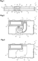
- An electronic device as shown in figure 1 and designated as a whole by the general reference 1, comprises an electronic circuit board 15 enclosed in a housing comprising a first part 2 and a second part 3.
- the electronic device 1 is a telematic control unit configured to be placed in an automotive vehicle and to communicate with a distant network.
- the second part 3 is configured to be fixed against the bodywork of the automotive vehicle.
- the first part 2 faces a first face 23 of the electronic circuit board and the second part faces a second face 24 of the electronic circuit board 15 opposite to the first face 23.
- the electronic device 1 presents a globally parallelepipedal shape with a first main face 4 (visible on figures 1 to 3 ) belonging to the first part 2, a second main face 5 (as visible on figures 1 , 4 and 5 ) opposite and parallel to the first main face 4 and belonging to the second part 3.
- the first main face 4 and the second main face 5 are connected by four side faces 6.
- the side faces are formed by the first part 2 and/or by the second part 3.
- the first part 2 and the second part 3 are fixed to each other, for instance clipped to each other.
- the electronic circuit board 15 is placed in the housing in such manner that a first face of the electronic circuit board 15 is parallel with the first main face 4 and a second face of the electronic circuit board 15 opposite to the first face is parallel to the second main face 5.
- the electronic circuit board 15 may overheat and may be damaged.
- the electronic device 1 comprise a heat dissipation system, comprising a first airflow channel 7 in the first part 2 of the housing and a second airflow channel 8 in the second part of the housing.
- the first airflow channel 7 and the second airflow channel 8 are both fed by a same airflow source 9, here a radial fan.
- the first airflow channel 7 extends in the first part 2 parallel to the electronic circuit board 15 between a first inlet 10 and a first outlet 11 (the wording "inlet” and “outlet” being dependent on the airflow direction).
- the first airflow channel 7 is not linear along the path followed by the airflow and forms a right angle.
- the first airflow channel 7 presents a rectangular cross section. It therefore comprises four walls, among which a first proximal wall 12 relatively to the electronic circuit board 15 (the wall which is closer to the electronic circuit board 15), a first distal wall 13 (the farthest wall from the electronic circuit board 15), and two first side wall 14 extending between the proximal wall and the distal wall.
- the first inlet 10 is located on a side face 6 and the first outlet 11 is located in a portion of the first proximal wall that is not in contact with the electronic circuit board 15 and that extends beyond the outline of the electronic circuit board 15.
- the airflow source 9 is located in the first airflow channel 7, here near the first inlet 10.
- the electronic device 1 comprises a second airflow channel 8 located in the second part of the housing.
- the second airflow channel 8 extends in the second part 3 parallel to the electronic circuit board 15 between a second inlet 16 and a second outlet 17.
- the second airflow channel 8 is not linear along the path followed by the airflow and forms a right angle.
- the second airflow channel 9 presents a rectangular cross section. It therefore comprises four walls, among which a second proximal wall 18 relatively to the electronic circuit board 15 (the wall which is closer to the electronic circuit board 15), a second distal wall 19 (the farthest wall from the electronic circuit board 15), and two second side wall 20 extending between the second proximal wall 18 and the second distal wall 20.
- the second proximal wall 18 is in contact with the electronic circuit board 15.
- the second proximal wall 18 comprised a material having a high thermal conductivity, for instance a metal and preferably aluminium.
- a plurality of heat dissipation fins 22, here eight heat dissipation fins, extends longitudinally in the second channel 8.
- the heat dissipation fins 22 protrudes from the second proximal wall 12, and are integrally formed with the second proximal wall 18.
- the second outlet 17 is located on a side face 6 and the second inlet 16 is located in a portion of the second proximal wall that that extends beyond the outline of the electronic circuit board 15, in vis-à-vis with the first outlet 11.
- the first outlet 11 and the second inlet 16 are connected and the first channel 7 and the second channel 8 forms a continuous channel extending in the first part 2 and in the second part 3.
- the first part 2 and the second part 3 are made in material that can easily be moulded, stamped, or die-casted.
- the first part excepted the first removable cover
- the second part excepted the second removable cover
- the removable covers are preferably in a material similar as the material of their corresponding parts.
- an airflow source located in the first channel, near the first inlet.
- the location of the airflow source is not limitative, and the airflow source may be located in the first or second channel, near any inlet or outlet, or at distance from the inlet and outlet, or outside the channel near an inlet or an outlet.
- one of the two channels comprising eight heat dissipation fins.
- the invention is not limited by this number of fins, and other embodiments comprise a different number of fins or no fins at all.
- both channels are provided with heat dissipation fins.
- the housing according to the invention may be made in any material.
- at least one of the first part and second part is made in a material having a good thermal conductivity, for instance a metal and preferably aluminium.
- at least one of the proximal walls are made in a material that is different from the material of their corresponding parts.
Landscapes
- Engineering & Computer Science (AREA)
- Microelectronics & Electronic Packaging (AREA)
- Physics & Mathematics (AREA)
- Thermal Sciences (AREA)
- Cooling Or The Like Of Electrical Apparatus (AREA)
Priority Applications (2)
| Application Number | Priority Date | Filing Date | Title |
|---|---|---|---|
| EP23196089.9A EP4521868A1 (de) | 2023-09-07 | 2023-09-07 | Elektronische vorrichtung |
| PCT/EP2024/074808 WO2025051844A1 (en) | 2023-09-07 | 2024-09-05 | Electronic device |
Applications Claiming Priority (1)
| Application Number | Priority Date | Filing Date | Title |
|---|---|---|---|
| EP23196089.9A EP4521868A1 (de) | 2023-09-07 | 2023-09-07 | Elektronische vorrichtung |
Publications (1)
| Publication Number | Publication Date |
|---|---|
| EP4521868A1 true EP4521868A1 (de) | 2025-03-12 |
Family
ID=87971851
Family Applications (1)
| Application Number | Title | Priority Date | Filing Date |
|---|---|---|---|
| EP23196089.9A Pending EP4521868A1 (de) | 2023-09-07 | 2023-09-07 | Elektronische vorrichtung |
Country Status (2)
| Country | Link |
|---|---|
| EP (1) | EP4521868A1 (de) |
| WO (1) | WO2025051844A1 (de) |
Citations (2)
| Publication number | Priority date | Publication date | Assignee | Title |
|---|---|---|---|---|
| EP1656009A2 (de) * | 2004-10-26 | 2006-05-10 | Comarco Wireless Technologies, Inc. | Leistungsanpassungsgerät mit einem Ventilator |
| DE202014104445U1 (de) * | 2014-09-18 | 2014-09-25 | Dr. Ing. H.C. F. Porsche Aktiengesellschaft | Anordnung mindestens eines elektronischen Steuergeräts in einem Kraftfahrzeug |
-
2023
- 2023-09-07 EP EP23196089.9A patent/EP4521868A1/de active Pending
-
2024
- 2024-09-05 WO PCT/EP2024/074808 patent/WO2025051844A1/en active Pending
Patent Citations (2)
| Publication number | Priority date | Publication date | Assignee | Title |
|---|---|---|---|---|
| EP1656009A2 (de) * | 2004-10-26 | 2006-05-10 | Comarco Wireless Technologies, Inc. | Leistungsanpassungsgerät mit einem Ventilator |
| DE202014104445U1 (de) * | 2014-09-18 | 2014-09-25 | Dr. Ing. H.C. F. Porsche Aktiengesellschaft | Anordnung mindestens eines elektronischen Steuergeräts in einem Kraftfahrzeug |
Also Published As
| Publication number | Publication date |
|---|---|
| WO2025051844A1 (en) | 2025-03-13 |
Similar Documents
| Publication | Publication Date | Title |
|---|---|---|
| US5947189A (en) | Heat exchanging system having cooling fan, for vehicle | |
| US7813135B2 (en) | Semiconductor device | |
| US11071233B1 (en) | Auxiliary-cooled electronics assembly with extruded cooling cavity | |
| EP3904149B1 (de) | Ladesteckerdüse | |
| US9461525B2 (en) | Electrical machine for use in the automotive sector | |
| JP2001308566A (ja) | 車両用制御ユニットの冷却構造 | |
| EP1190878B1 (de) | Gebläsegeschwindigkeitssteuerung, montiert auf einem Verdampfer | |
| CN104144807B (zh) | 电加热流体的装置、相关供暖和/或空气调节设备 | |
| WO2018150795A1 (ja) | 熱媒体加熱装置、及び車両用空調装置 | |
| WO2007094491A1 (ja) | コンデンサ装置 | |
| US10454333B2 (en) | Actuator | |
| US20130120915A1 (en) | Connection Device for Connecting an Electronic Component to a Housing Part and Electronic Controller | |
| US6130818A (en) | Electronic assembly with fault tolerant cooling | |
| US11547026B2 (en) | Electric vehicle and power converter thereof | |
| WO2025051844A1 (en) | Electronic device | |
| US7265978B2 (en) | Control apparatus having fluid passage for cooling purpose | |
| CN111836734B (zh) | 鼓风机控制模块以及相应的供暖和/或通风和/或空调装置 | |
| US20150328955A1 (en) | Ventilation device for a ventilation, heating and/or air-conditioning unit | |
| EP3943370A1 (de) | Spoiler eines fahrzeuges | |
| US11359716B2 (en) | Drive device for vehicles | |
| US20220046809A1 (en) | Vehicle display carrier with heat sink | |
| KR102499012B1 (ko) | 제어기 일체형 eop의 방열장치 | |
| KR101063172B1 (ko) | 전자제어장치 | |
| CN120499994A (zh) | 换热装置、车载电子设备及车辆 | |
| US20050199382A1 (en) | Heat transmitter arrangement |
Legal Events
| Date | Code | Title | Description |
|---|---|---|---|
| PUAI | Public reference made under article 153(3) epc to a published international application that has entered the european phase |
Free format text: ORIGINAL CODE: 0009012 |
|
| STAA | Information on the status of an ep patent application or granted ep patent |
Free format text: STATUS: THE APPLICATION HAS BEEN PUBLISHED |
|
| AK | Designated contracting states |
Kind code of ref document: A1 Designated state(s): AL AT BE BG CH CY CZ DE DK EE ES FI FR GB GR HR HU IE IS IT LI LT LU LV MC ME MK MT NL NO PL PT RO RS SE SI SK SM TR |
|
| STAA | Information on the status of an ep patent application or granted ep patent |
Free format text: STATUS: REQUEST FOR EXAMINATION WAS MADE |
|
| 17P | Request for examination filed |
Effective date: 20250908 |