EP4523516A1 - Robot de travail automoteur - Google Patents
Robot de travail automoteur Download PDFInfo
- Publication number
- EP4523516A1 EP4523516A1 EP23803317.9A EP23803317A EP4523516A1 EP 4523516 A1 EP4523516 A1 EP 4523516A1 EP 23803317 A EP23803317 A EP 23803317A EP 4523516 A1 EP4523516 A1 EP 4523516A1
- Authority
- EP
- European Patent Office
- Prior art keywords
- unit
- self
- target
- propelled work
- robot
- Prior art date
- Legal status (The legal status is an assumption and is not a legal conclusion. Google has not performed a legal analysis and makes no representation as to the accuracy of the status listed.)
- Pending
Links
Images




Classifications
-
- A—HUMAN NECESSITIES
- A01—AGRICULTURE; FORESTRY; ANIMAL HUSBANDRY; HUNTING; TRAPPING; FISHING
- A01D—HARVESTING; MOWING
- A01D46/00—Picking of fruits, vegetables, hops, or the like; Devices for shaking trees or shrubs
- A01D46/30—Robotic devices for individually picking crops
-
- G—PHYSICS
- G05—CONTROLLING; REGULATING
- G05D—SYSTEMS FOR CONTROLLING OR REGULATING NON-ELECTRIC VARIABLES
- G05D1/00—Control of position, course, altitude or attitude of land, water, air or space vehicles, e.g. using automatic pilots
- G05D1/60—Intended control result
- G05D1/617—Safety or protection, e.g. defining protection zones around obstacles or avoiding hazards
- G05D1/622—Obstacle avoidance
-
- A—HUMAN NECESSITIES
- A01—AGRICULTURE; FORESTRY; ANIMAL HUSBANDRY; HUNTING; TRAPPING; FISHING
- A01D—HARVESTING; MOWING
- A01D75/00—Accessories for harvesters or mowers
- A01D75/18—Safety devices for parts of the machines
- A01D75/185—Avoiding collisions with obstacles
-
- B—PERFORMING OPERATIONS; TRANSPORTING
- B25—HAND TOOLS; PORTABLE POWER-DRIVEN TOOLS; MANIPULATORS
- B25J—MANIPULATORS; CHAMBERS PROVIDED WITH MANIPULATION DEVICES
- B25J19/00—Accessories fitted to manipulators, e.g. for monitoring, for viewing; Safety devices combined with or specially adapted for use in connection with manipulators
- B25J19/0058—Means for cleaning manipulators, e.g. dust removing means
-
- B—PERFORMING OPERATIONS; TRANSPORTING
- B25—HAND TOOLS; PORTABLE POWER-DRIVEN TOOLS; MANIPULATORS
- B25J—MANIPULATORS; CHAMBERS PROVIDED WITH MANIPULATION DEVICES
- B25J5/00—Manipulators mounted on wheels or on carriages
- B25J5/007—Manipulators mounted on wheels or on carriages mounted on wheels
-
- B—PERFORMING OPERATIONS; TRANSPORTING
- B25—HAND TOOLS; PORTABLE POWER-DRIVEN TOOLS; MANIPULATORS
- B25J—MANIPULATORS; CHAMBERS PROVIDED WITH MANIPULATION DEVICES
- B25J9/00—Program-controlled manipulators
- B25J9/16—Program controls
- B25J9/1615—Program controls characterised by special kind of manipulator, e.g. planar, scara, gantry, cantilever, space, closed chain, passive/active joints and tendon driven manipulators
- B25J9/162—Mobile manipulator, movable base with manipulator arm mounted on it
-
- B—PERFORMING OPERATIONS; TRANSPORTING
- B25—HAND TOOLS; PORTABLE POWER-DRIVEN TOOLS; MANIPULATORS
- B25J—MANIPULATORS; CHAMBERS PROVIDED WITH MANIPULATION DEVICES
- B25J9/00—Program-controlled manipulators
- B25J9/16—Program controls
- B25J9/1694—Program controls characterised by use of sensors other than normal servo-feedback from position, speed or acceleration sensors, perception control, multi-sensor controlled systems, sensor fusion
- B25J9/1697—Vision controlled systems
-
- G—PHYSICS
- G05—CONTROLLING; REGULATING
- G05D—SYSTEMS FOR CONTROLLING OR REGULATING NON-ELECTRIC VARIABLES
- G05D1/00—Control of position, course, altitude or attitude of land, water, air or space vehicles, e.g. using automatic pilots
- G05D1/20—Control system inputs
- G05D1/24—Arrangements for determining position or orientation
- G05D1/242—Means based on the reflection of waves generated by the vehicle
-
- G—PHYSICS
- G05—CONTROLLING; REGULATING
- G05D—SYSTEMS FOR CONTROLLING OR REGULATING NON-ELECTRIC VARIABLES
- G05D1/00—Control of position, course, altitude or attitude of land, water, air or space vehicles, e.g. using automatic pilots
- G05D1/20—Control system inputs
- G05D1/24—Arrangements for determining position or orientation
- G05D1/244—Arrangements for determining position or orientation using passive navigation aids external to the vehicle, e.g. markers, reflectors or magnetic means
-
- G—PHYSICS
- G05—CONTROLLING; REGULATING
- G05D—SYSTEMS FOR CONTROLLING OR REGULATING NON-ELECTRIC VARIABLES
- G05D1/00—Control of position, course, altitude or attitude of land, water, air or space vehicles, e.g. using automatic pilots
- G05D1/60—Intended control result
- G05D1/656—Interaction with payloads or external entities
- G05D1/689—Pointing payloads towards fixed or moving targets
- G05D1/6895—Pointing payloads towards fixed or moving targets the payload being a manipulator arm
-
- G—PHYSICS
- G05—CONTROLLING; REGULATING
- G05B—CONTROL OR REGULATING SYSTEMS IN GENERAL; FUNCTIONAL ELEMENTS OF SUCH SYSTEMS; MONITORING OR TESTING ARRANGEMENTS FOR SUCH SYSTEMS OR ELEMENTS
- G05B2219/00—Program-control systems
- G05B2219/30—Nc systems
- G05B2219/40—Robotics, robotics mapping to robotics vision
- G05B2219/40298—Manipulator on vehicle, wheels, mobile
-
- G—PHYSICS
- G05—CONTROLLING; REGULATING
- G05B—CONTROL OR REGULATING SYSTEMS IN GENERAL; FUNCTIONAL ELEMENTS OF SUCH SYSTEMS; MONITORING OR TESTING ARRANGEMENTS FOR SUCH SYSTEMS OR ELEMENTS
- G05B2219/00—Program-control systems
- G05B2219/30—Nc systems
- G05B2219/45—Nc applications
- G05B2219/45003—Harvester
-
- G—PHYSICS
- G05—CONTROLLING; REGULATING
- G05D—SYSTEMS FOR CONTROLLING OR REGULATING NON-ELECTRIC VARIABLES
- G05D2105/00—Specific applications of the controlled vehicles
- G05D2105/15—Specific applications of the controlled vehicles for harvesting, sowing or mowing in agriculture or forestry
-
- G—PHYSICS
- G05—CONTROLLING; REGULATING
- G05D—SYSTEMS FOR CONTROLLING OR REGULATING NON-ELECTRIC VARIABLES
- G05D2107/00—Specific environments of the controlled vehicles
- G05D2107/20—Land use
- G05D2107/21—Farming, e.g. fields, pastures or barns
-
- G—PHYSICS
- G05—CONTROLLING; REGULATING
- G05D—SYSTEMS FOR CONTROLLING OR REGULATING NON-ELECTRIC VARIABLES
- G05D2109/00—Types of controlled vehicles
- G05D2109/10—Land vehicles
-
- G—PHYSICS
- G05—CONTROLLING; REGULATING
- G05D—SYSTEMS FOR CONTROLLING OR REGULATING NON-ELECTRIC VARIABLES
- G05D2111/00—Details of signals used for control of position, course, altitude or attitude of land, water, air or space vehicles
- G05D2111/10—Optical signals
Definitions
- the present disclosure relates to a self-propelled work robot.
- PATENT LITERATURE 1 JP2021-101653A
- a robot arm that performs work is configured to be switchable between an operation permission mode in which operation is permitted and an operation restriction mode in which operation is restricted.
- an operation permission mode in which operation is permitted
- an operation restriction mode in which operation is restricted.
- the self-propelled work robot may travel, and there may be a person.
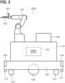
- the control device 120 executes a control program to virtually implement, by using software, an operation control unit 121, a traveling control unit 122, a safety monitoring unit 123, an operation mode switching unit 124, a detection area switching unit 125, and a form switching unit 126.
- These processing units may include hardware, or may include a combination of software and hardware.
- the operation control unit 121 is configured to control overall operation of the self-propelled work robot 100.
- the operation control unit 121 controls overall operation of the entire robot arm 102 while recognizing orientation, speed, position, and the like of each unit of the robot arm 102.
- the operation control unit 121 controls overall harvest operation by the harvest tool 103.
- the operation control unit 121 controls overall imaging operation by the camera 104.
- the operation control unit 121 analyzes an image captured by the camera 104, recognizes a position, orientation, and the like of the crop T, which is a work object, and specifies a cutting point.
- the operation control unit 121 operates the robot arm 102 so that the harvest tool 103 reaches a specified cutting point.
- the operation control unit 121 operates the harvest tool 103 at the specified cutting point.
- the operation control unit 121 is configured to harvest the crop T, which is the work object, with the robot arm 102 on which the harvest tool 103 and the camera 104 are mounted.
- the self-propelled work robot 100 may include a collection box that contains the crop T harvested by the robot arm 102.
- the self-propelled work robot 100 when traveling in an area other than the work areas R1 in the agricultural field 10, the self-propelled work robot 100 travels mainly with rotation of the large wheel parts 106a. Meanwhile, when traveling in the work areas R1 in the agricultural field 10, the self-propelled work robot 100 travels mainly with rotation of the small wheel parts 106b. Therefore, if the driving wheels 106 are rotated at the same rotational speed regardless of an area where the self-propelled work robot 100 travels, the moving speed of the self-propelled work robot 100 when traveling in an area other than the work areas R1 is relatively high, and the moving speed of the self-propelled work robot 100 when traveling in the work areas R1 is relatively low.
- the passage traveling time mode is a traveling mode in which the self-propelled work robot 100 is assumed to travel in an area other than the work areas R1, and in which the self-propelled work robot 100 can travel at a predetermined low speed or stop.
- the predetermined low speed can be appropriately changed and set within a speed range in which sufficient safety is ensured and within a speed range lower than the predetermined high speed described above.
- the safety monitoring unit 123 is configured to monitor at least whether behaviors of the robot arm 102 and the traveling unit 105 are in a safe state.
- the safety monitoring unit 123 is configured to monitor whether a behavior of the entire self-propelled work robot 100 is in a safe state.
- the safety monitoring unit 123 functions as a control unit that controls behaviors of the robot arm 102, the traveling unit 105, and the entire self-propelled work robot 100.
- As the safe state an appropriate state can be set on an assumption that the self-propelled work robot 100 does not harm at least a person.
- the safety monitoring unit 123 desirably includes a control unit that has acquired a predetermined safety certification.
- the detection area switching unit 125 is configured to switch an area in which the obstacle detection sensors 109 detects an obstacle. In this case, the detection area switching unit 125 is configured to switch the obstacle detection area, according to states of the hot-water pipe 12 detected by the hot-water pipe detection sensors 110.
- the traveling control unit 122 decelerates the moving speed of the self-propelled work robot 100 to a first speed for non-work time.
- the first speed for non-work time can be appropriately changed and set within a speed range lower than a speed for non-work time set as the moving speed of the self-propelled work robot 100 in an area other than the work areas R1.
- the speed for non-work time can be appropriately changed and set within a speed range in which sufficient safety is ensured when the self-propelled work robot 100 travels in an area other than the work areas R1.
- the traveling control unit 122 decelerates the moving speed of the self-propelled work robot 100 to a second speed for non-work time.
- the second speed for non-work time can be appropriately changed and set within a speed range lower than the first speed for non-work time.
- the traveling control unit 122 stops the self-propelled work robot 100 from traveling.
- the detection area switching unit 125 switches the area in which the obstacle detection sensors 109 detect an obstacle to an in-lane pattern Pb as exemplified in FIG. 4 .
- the in-lane pattern Pb can also be defined as a work time pattern in which the robot arm 102 is assumed to perform work.
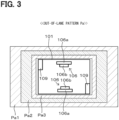
- a plurality of detection areas in this case, a first deceleration area Pb1, a second deceleration area Pb2, and a stop area Pb3 is formed.
- the first deceleration area Pb1, the second deceleration area Pb2, and the stop area Pb3 are all long rectangular detection areas at a front and rear of the self-propelled work robot 100, extending along a shorter direction of the self-propelled work robot 100.
- the first deceleration area Pb1 is provided outside the second deceleration area Pb2, the second deceleration area Pb2 is provided outside the stop area Pb3, and the stop area Pb3 is provided outside the self-propelled work robot 100.
- the in-lane pattern Pb is a detection area pattern that includes the front and rear sides of the self-propelled work robot 100 and does not include the left and right sides of the self-propelled work robot 100. That is, the in-lane pattern Pb is a detection area pattern that covers an area along the traveling direction of the self-propelled work robot 100 in the work area R1.
- the traveling control unit 122 decelerates the moving speed of the self-propelled work robot 100 to a first speed for work time.
- the first speed for work time can be appropriately changed and set within a speed range lower than a speed for work time set as the moving speed of the self-propelled work robot 100 in the work areas R1.
- the speed for work time can be appropriately changed and set within a speed range in which sufficient safety is ensured when the self-propelled work robot 100 travels in the work areas R1.
- the traveling control unit 122 decelerates the moving speed of the self-propelled work robot 100 to a second speed for work time.
- the second speed for work time can be appropriately changed and set within a speed range lower than the first speed for work time.
- the traveling control unit 122 stops the self-propelled work robot 100 from traveling.
- the speed for work time is assumed to be a speed lower than the speed for non-work time
- the first speed for work time is assumed to be a speed lower than the first speed for non-work time
- the second speed for work time is assumed to be a speed lower than the second speed for non-work time.
- the robot arm 102 may come into contact with a person or an obstacle in the middle of the transformation.
- the hot-water pipe detection sensor 110 on the front side indicates the detected state
- the hot-water pipe detection sensor 110 on the rear side indicates the detected state.
- the control device 120 switches the area in which the obstacle detection sensors 109 detect an obstacle to the in-lane pattern Pb.
- control device 120 determines that the self-propelled work robot 100 is present in the work area R1, and there is no obstacle around the self-propelled work robot 100, in this case, in front of and behind the self-propelled work robot 100.
- the obstacle detection sensor 109 on the front side indicates the detected state
- the obstacle detection sensor 109 on the rear side indicates the undetected state
- control device 120 determines that the self-propelled work robot 100 is present in the work area R1, and there is an obstacle around the self-propelled work robot 100, in this case, in front of the self-propelled work robot 100.
- the control device 120 switches the traveling mode of the traveling unit 105 to the harvest time mode to enable traveling at the predetermined high speed. However, it is detected that there is an obstacle in front of the self-propelled work robot 100. Therefore, while switching the traveling mode of the traveling unit 105 to the harvest time mode, the control device 120, adjusts the moving speed of the self-propelled work robot 100 to the predetermined low speed, and, in some cases, stops the self-propelled work robot 100 from traveling.
- the hot-water pipe detection sensor 110 on the front side indicates the detected state
- the hot-water pipe detection sensor 110 on the rear side indicates the undetected state.
- one of the two front and rear hot-water pipe detection sensors 110 of the self-propelled work robot 100 indicates the undetected state. Therefore, it can be determined that the self-propelled work robot 100 is in the middle of moving from outside of the work area R1 to inside of the work area R1, or in the middle of moving from the inside of the work area R1 to the outside of the work area R1.
- the control device 120 switches the area in which the obstacle detection sensors 109 detect an obstacle to the in-lane pattern Pb. That is, the control device 120 is configured to switch the area in which the obstacle detection sensors 109 detect an obstacle to the in-lane pattern Pb unless the entire self-propelled work robot 100 moves out of the work area R1, in other words, as long as a part of the self-propelled work robot 100 remains in the work area R1.
- the control device 120 may switch the area in which the obstacle detection sensors 109 detect an obstacle to the out-of-lane pattern Pa, in a case where at least a part of the obstacle detection area has moved to the outside of the work area R1.
- the obstacle detection sensor 109 on the front side indicates an undetected state
- the obstacle detection sensor 109 on the rear side indicates the undetected state
- control device 120 determines that the self-propelled work robot 100 is in the middle of moving from outside of the work area R1 to inside of the work area R1, or in the middle of moving from the inside of the work area R1 to the outside of the work area R1.
- the control device 120 determines that there is no obstacle around the self-propelled work robot 100, in this case, in front of and behind the self-propelled work robot 100.
- the control device 120 switches the traveling mode of the traveling unit 105 to the transition time mode to enable traveling at the predetermined low speed.
- the control device 120 switches the operation mode of the robot arm 102 to the operation restriction mode to restrict operation by the robot arm 102. Accordingly, the self-propelled work robot 100 can move from the outside of the work area R1 to the inside of the work area R1 or from the inside of the work area R1 to the outside of the work area R1 in a state where the operation of the robot arm 102 is restricted. At this time, for example, the control device 120 may maintain a state where the operation of the robot arm 102 is stopped.
- the control device 120 may perform control similar to control for the status pattern C described above.
- the hot-water pipe detection sensor 110 on the front side indicates the undetected state
- the hot-water pipe detection sensor 110 on the rear side indicates the undetected state.
- both the two front and rear hot-water pipe detection sensors 110 of the self-propelled work robot 100 indicate the undetected state. Therefore, it can be determined that the self-propelled work robot 100 is present in an area other than the work areas R1. Therefore, the control device 120 switches the area in which the obstacle detection sensors 109 detect an obstacle to the out-of-lane pattern Pa.
- the obstacle detection sensor 109 on the front side indicates the undetected state
- the obstacle detection sensor 109 on the rear side indicates the undetected state
- the obstacle detection sensor 109 on the front side indicates the detected state
- the obstacle detection sensor 109 on the rear side indicates the undetected state
- the operation mode of the robot arm 102 can be appropriately switched according to states of the hot-water pipes 12 detected by the hot-water pipe detection sensors 110. Accordingly, for example, by providing the hot-water pipe 12 in an area for which the operation mode of the robot arm 102 is desired to be switched, which is the work area R1 in this case, the operation mode of the robot arm 102 can be accurately switched to the operation permission mode and the operation restriction mode according to the area where the self-propelled work robot 100 is present.
- the robot main body 101 and eventually the entire self-propelled work robot 100 travels with the traveling unit 105, on the hot-water pipe 12 as the target.
- the hot-water pipe 12 as the target is immediately below the traveling self-propelled work robot 100. Therefore, the hot-water pipe 12 can be more easily detected.
- the self-propelled work robot 100 includes the obstacle detection sensors 109 that detect an obstacle present around the robot main body 101, and the detection area switching unit 125 that switches the area in which the obstacle detection sensors 109 detect an obstacle.
- the detection area switching unit 125 switches the area to be detected by the obstacle detection sensors 109 according to states of the hot-water pipe 12 detected by the hot-water pipe detection sensors 110.
- the hot-water pipe 12 In a state where the hot-water pipe 12 is detected by the hot-water pipe detection sensors 110, it is highly possible that the self-propelled work robot 100 is present in the work area R1. Therefore, by switching the area in which the obstacle detection sensors 109 detect an obstacle to an area suitable for work time, in this case, the in-lane pattern Pb, for example, it is possible to prevent the cultivation facilities 11a or the support member 11b from being detected as an obstacle.
- the self-propelled work robot 100 is present in an area other than the work areas R1. Therefore, by switching the area in which the obstacle detection sensors 109 detect an obstacle to an area suitable for non-work time, in this case, the out-of-lane pattern Pa, for example, it is possible to sense a person present in an area other than the work areas R1 as an obstacle, and thus to improve safety.
- the robot arm 102 is able to be switched between at least the operation permission mode in which operation is permitted and the operation restriction mode in which the operation is restricted.
- the operation mode switching unit 124 switches the operation mode of the robot arm 102 from the operation restriction mode to the operation permission mode in a case where the hot-water pipe detection sensors 110 have detected the hot-water pipe 12.
- the self-propelled work robot 100 is present in an area other than the work areas R1. Therefore, it is possible to improve safety by switching the operation mode of the robot arm 102 from the operation permission mode to the operation restriction mode.
- the hot-water pipe detection sensors 110 are provided at the front portion and rear portion of the robot main body 101 in the traveling direction.
- the self-propelled work robot 100 includes the form switching unit 126 that switches the form of the robot arm 102 according to states of the hot-water pipe 12 detected by the hot-water pipe detection sensors 110.
- the robot arm 102 is able to be switched between the detection time form set as the form to be taken or form recommended in a case where the hot-water pipe detection sensors 110 have detected the hot-water pipe 12, and the non-detection time form set as the form to be taken or form recommended in a case where the hot-water pipe detection sensors 110 have not detected the hot-water pipe 12.
- the form switching unit 126 switches the form of the robot arm 102 from the detection time form to the non-detection time form in a case where the hot-water pipe detection sensors 110 have not detected the hot-water pipe 12 and the robot arm 102 is switched to the detection time form.
- the form switching unit 126 switches the form of the robot arm 102 from the detection time form to the non-detection time form, after the robot main body 101 causes the traveling unit 105 to travel until the hot-water pipe detection sensors 110 are ready to detect the hot-water pipe 12.
- the self-propelled work robot 100 In a state where the hot-water pipe 12 is not detected by the hot-water pipe detection sensors 110, it is highly possible that the self-propelled work robot 100 is present in an area other than the work areas R1. Therefore, if the form of the robot arm 102 is switched in this state, the robot arm 102 may come into contact with a person. Meanwhile, in a state where the hot-water pipe 12 is detected by the hot-water pipe detection sensors 110, it is highly possible that the self-propelled work robot 100 is present in the work area R1, and it is less likely that a person is present in the work area R1.
- the self-propelled work robot 100 includes the harvest tool 103 provided on the robot arm 102 and the disinfection unit 108 for disinfection of the harvest tool 103. Therefore, for example, a form in which the harvest tool 103 has moved into the disinfection unit 108 may be set as the non-detection time form.
- the robot arm 102 is set to the non-detection time form mainly at the non-work time when the work by the robot arm 102 is not performed. Therefore, by adopting the form for the harvest tool 103 moved into the disinfection unit 108 as the non-detection time form, it is possible to disinfect the harvest tool 103 with the disinfection unit 108 during the non-work time, and thus efficiently perform disinfection work.
- the self-propelled work robot 100 includes the camera 104 provided on the robot arm 102. Therefore, for example, a form in which the camera 104 has moved to a position where an image of the predetermined imaging target can be captured by the camera 104 may be set as the non-detection time form.
- the robot arm 102 is set to the non-detection time form mainly in the non-work time when the work by the robot arm 102 is not performed, and the self-propelled work robot 100 is assumed to travel in an area other than the work areas R1 during the non-work time. Therefore, by adopting, as the non-detection time form, a form in which the camera 104 has moved to a position where an image of the predetermined imaging target object, which is the trace lines 13, the markers 14 and 15, or the like, for example, can be captured, it is possible to facilitate image capturing of the imaging target object when the self-propelled work robot 100 travels in the non-work time, and thus to easily support the self-propelled work robot 100 traveling in the non-work time.
- traveling unit 105 is able to switch a rotational speed of the driving wheels 106, which move the robot main body 101 and eventually the entire self-propelled work robot 100, according to states of the hot-water pipe 12 detected by the hot-water pipe detection sensors 110.
- the driving wheels 106 are rotated at the same rotational speed between a case where the large wheel parts 106a are mainly used to travel in an area other than the work areas R1 and a case where the small wheel parts 106b are mainly used to travel on the hot-water pipes 12 in the work area R1, the moving speed of the self-propelled work robot 100 when traveling in an area other than the work areas R1 is relatively high, and the moving speed of the self-propelled work robot 100 when traveling in the work areas R1 is relatively low.
- an increase in rotational speed of the driving wheels 106 means an increase in rotational speed of the small wheel parts 106b, not the large wheel parts 106a. Therefore, the moving speed of the entire self-propelled work robot 100 is not increased so much.
- the obstacle detection sensor 109 may detect, for example, a wall or the like present at an end of the work area R1 as an obstacle, even if the self-propelled work robot 100 in the work area R1 is sufficiently away from the end of the work area R1.
- control for reducing the moving speed of the self-propelled work robot 100 or control for stopping the self-propelled work robot may be performed even in a state where the self-propelled work robot 100 reaches close to the end of the work area R1.
- the self-propelled work robot 100 is configured so that the area in which the obstacle detection sensors 109 detect an obstacle is switched to the in-lane pattern Pb in a case where the self-propelled work robot 100 is present in the work area R1. Therefore, even if the traveling speed of the self-propelled work robot 100 in the work area R1 is increased, the area in which the obstacle detection sensors 109 detect an obstacle can be set to an area that is not excessively wide and is suitable for traveling in the work area R1. Therefore, it is possible to prevent control for reducing the moving speed of the self-propelled work robot or control for stopping the self-propelled work robot 100 even if there is still a distance to the end of the work area R1.
- the self-propelled work robot 100 includes the safety monitoring unit 123 that monitors whether a behavior of the entire self-propelled work robot 100 including at least the robot arm 102 and the traveling unit 105 is in a safe state.
- the safety monitoring unit 123 functions as a control unit that controls the behavior of the entire self-propelled work robot 100 including at least the robot arm 102 and the traveling unit 105. According to the configuration example, the work by and traveling of the self-propelled work robot 100 can be performed in a safe state on the basis of control by the control unit.
- the safety monitoring unit 123 includes the control unit that has acquired a predetermined safety certification, by which it is possible to further guarantee safety.
- Various sensors such as the hot-water pipe detection sensors 110, the obstacle detection sensors 109, and the like also include a sensor that has acquired a predetermined safety certification, by which it is possible to further guarantee safety.
- Other components that constitute the self-propelled work robot 100 include a component that has acquired a predetermined safety certification, by which it is possible to further guarantee safety.
- As the safety certification it is possible to adopt various safety certification standards including a standard stipulated by the International Organization for Standardization (ISO) and the like, for example.
- ISO International Organization for Standardization
- a self-propelled work robot 100 includes hot-water pipe detection sensors 110 on both sides in a shorter direction of the robot main body 101.
Landscapes
- Engineering & Computer Science (AREA)
- Robotics (AREA)
- Aviation & Aerospace Engineering (AREA)
- Radar, Positioning & Navigation (AREA)
- Remote Sensing (AREA)
- Physics & Mathematics (AREA)
- General Physics & Mathematics (AREA)
- Automation & Control Theory (AREA)
- Mechanical Engineering (AREA)
- Life Sciences & Earth Sciences (AREA)
- Environmental Sciences (AREA)
- Health & Medical Sciences (AREA)
- General Health & Medical Sciences (AREA)
- Orthopedic Medicine & Surgery (AREA)
- Manipulator (AREA)
- Control Of Position, Course, Altitude, Or Attitude Of Moving Bodies (AREA)
Applications Claiming Priority (2)
| Application Number | Priority Date | Filing Date | Title |
|---|---|---|---|
| JP2022078208 | 2022-05-11 | ||
| PCT/JP2023/014728 WO2023218835A1 (fr) | 2022-05-11 | 2023-04-11 | Robot de travail automoteur |
Publications (2)
| Publication Number | Publication Date |
|---|---|
| EP4523516A1 true EP4523516A1 (fr) | 2025-03-19 |
| EP4523516A4 EP4523516A4 (fr) | 2025-09-10 |
Family
ID=88730104
Family Applications (1)
| Application Number | Title | Priority Date | Filing Date |
|---|---|---|---|
| EP23803317.9A Pending EP4523516A4 (fr) | 2022-05-11 | 2023-04-11 | Robot de travail automoteur |
Country Status (7)
| Country | Link |
|---|---|
| US (1) | US20250053178A1 (fr) |
| EP (1) | EP4523516A4 (fr) |
| JP (1) | JP7619527B2 (fr) |
| CN (1) | CN119212828A (fr) |
| AU (1) | AU2023268200A1 (fr) |
| CA (1) | CA3252642A1 (fr) |
| WO (1) | WO2023218835A1 (fr) |
Families Citing this family (3)
| Publication number | Priority date | Publication date | Assignee | Title |
|---|---|---|---|---|
| WO2025234271A1 (fr) * | 2024-05-08 | 2025-11-13 | 株式会社デンソー | Système de récolte de culture |
| WO2025234269A1 (fr) * | 2024-05-08 | 2025-11-13 | 株式会社デンソー | Robot de récolte |
| JP7789148B1 (ja) | 2024-08-30 | 2025-12-19 | 三菱重工業株式会社 | 作業ロボット、作業ロボットの制御方法 |
Family Cites Families (8)
| Publication number | Priority date | Publication date | Assignee | Title |
|---|---|---|---|---|
| JPH1110568A (ja) * | 1997-06-26 | 1999-01-19 | Mitsubishi Electric Corp | 無人搬送装置 |
| JP5768828B2 (ja) | 2013-03-15 | 2015-08-26 | 株式会社安川電機 | ロボットシステム、及び、ロボットシステムの制御方法 |
| GB2580991B (en) * | 2019-07-22 | 2021-05-05 | Kingdom Tech Ltd | Robotic lawn mower control |
| JP7382597B2 (ja) * | 2019-11-28 | 2023-11-17 | 川崎重工業株式会社 | ロボットシステムおよびロボットセル |
| JP7140097B2 (ja) * | 2019-12-25 | 2022-09-21 | 株式会社デンソー | 農作物収穫システム |
| JP7421346B2 (ja) | 2020-01-17 | 2024-01-24 | 川崎重工業株式会社 | 安全装置、自走式ロボットシステム、及び制御方法 |
| JP7322722B2 (ja) | 2020-01-27 | 2023-08-08 | トヨタ自動車株式会社 | 作業システム |
| JP7608094B2 (ja) * | 2020-09-11 | 2025-01-06 | 株式会社東芝 | 移動体、制御装置、監視装置、制御方法、及びプログラム |
-
2023
- 2023-04-11 EP EP23803317.9A patent/EP4523516A4/fr active Pending
- 2023-04-11 JP JP2024520306A patent/JP7619527B2/ja active Active
- 2023-04-11 WO PCT/JP2023/014728 patent/WO2023218835A1/fr not_active Ceased
- 2023-04-11 AU AU2023268200A patent/AU2023268200A1/en active Pending
- 2023-04-11 CA CA3252642A patent/CA3252642A1/fr active Pending
- 2023-04-11 CN CN202380039453.2A patent/CN119212828A/zh active Pending
-
2024
- 2024-10-29 US US18/929,826 patent/US20250053178A1/en active Pending
Also Published As
| Publication number | Publication date |
|---|---|
| WO2023218835A1 (fr) | 2023-11-16 |
| CA3252642A1 (fr) | 2025-07-08 |
| EP4523516A4 (fr) | 2025-09-10 |
| CN119212828A (zh) | 2024-12-27 |
| JP7619527B2 (ja) | 2025-01-22 |
| AU2023268200A1 (en) | 2024-10-17 |
| JPWO2023218835A1 (fr) | 2023-11-16 |
| US20250053178A1 (en) | 2025-02-13 |
Similar Documents
| Publication | Publication Date | Title |
|---|---|---|
| EP4523516A1 (fr) | Robot de travail automoteur | |
| US20260041502A1 (en) | Surgical system with obstacle indication system | |
| ES2877218T3 (es) | Aparato de tratamiento de suelos que se desplaza automáticamente dentro de un entorno | |
| US8855812B2 (en) | System and method for robot safety and collision avoidance | |
| US20140207285A1 (en) | System and method for monitoring entry of object into surrounding area of robot | |
| US9808137B2 (en) | Floor treatment machine and method for treating floor surfaces | |
| EP4140288B1 (fr) | Système et procédé d'agriculture autonome mobile | |
| US8315735B2 (en) | Production system having cooperating process area between human and robot | |
| KR20210038917A (ko) | 수확기, 주행 시스템, 주행 방법, 주행 프로그램 및 기억 매체 | |
| US11903379B2 (en) | System and method for performing spraying operations with an agricultural sprayer | |
| CN114564022B (zh) | 一种机器人碰撞处理方法及装置 | |
| CN108334069A (zh) | 自动行驶作业车 | |
| JP2018113937A (ja) | 自動走行作業車 | |
| CN109254580B (zh) | 用于自动行走式的服务设备的运行方法 | |
| JP2017127290A (ja) | 農業用作業車両 | |
| JP2000033592A (ja) | 生産システム | |
| JP2016187305A (ja) | 移動農機 | |
| CN115697843B (zh) | 拍摄系统及机器人系统 | |
| JP5214539B2 (ja) | 自律走行ロボット、自律走行ロボットを用いた追走システム、及び追走方法 | |
| JP7138041B2 (ja) | 移動体 | |
| US20240100691A1 (en) | Self-propelled Device | |
| ES3057724T3 (en) | Robotic manufacturing systems and methods | |
| CN215433657U (zh) | 机器人清洗控制系统 | |
| ES2998384T3 (en) | Method of handling safety, control system and industrial system | |
| CN111624989B (zh) | 控制方法及自移动设备 |
Legal Events
| Date | Code | Title | Description |
|---|---|---|---|
| STAA | Information on the status of an ep patent application or granted ep patent |
Free format text: STATUS: THE INTERNATIONAL PUBLICATION HAS BEEN MADE |
|
| PUAI | Public reference made under article 153(3) epc to a published international application that has entered the european phase |
Free format text: ORIGINAL CODE: 0009012 |
|
| STAA | Information on the status of an ep patent application or granted ep patent |
Free format text: STATUS: REQUEST FOR EXAMINATION WAS MADE |
|
| 17P | Request for examination filed |
Effective date: 20241010 |
|
| AK | Designated contracting states |
Kind code of ref document: A1 Designated state(s): AL AT BE BG CH CY CZ DE DK EE ES FI FR GB GR HR HU IE IS IT LI LT LU LV MC ME MK MT NL NO PL PT RO RS SE SI SK SM TR |
|
| DAV | Request for validation of the european patent (deleted) | ||
| DAX | Request for extension of the european patent (deleted) | ||
| STAA | Information on the status of an ep patent application or granted ep patent |
Free format text: STATUS: EXAMINATION IS IN PROGRESS |
|
| A4 | Supplementary search report drawn up and despatched |
Effective date: 20250808 |
|
| RIC1 | Information provided on ipc code assigned before grant |
Ipc: A01D 46/30 20060101AFI20250804BHEP Ipc: A01D 75/18 20060101ALI20250804BHEP Ipc: G05D 1/622 20240101ALI20250804BHEP Ipc: B25J 5/00 20060101ALI20250804BHEP Ipc: B25J 19/00 20060101ALI20250804BHEP |
|
| 17Q | First examination report despatched |
Effective date: 20250822 |