EP4523563A1 - Kettenglied für einen artikel, kettel mit einem solchen glied und artikel mit einem solchen kettenglied - Google Patents
Kettenglied für einen artikel, kettel mit einem solchen glied und artikel mit einem solchen kettenglied Download PDFInfo
- Publication number
- EP4523563A1 EP4523563A1 EP24180286.7A EP24180286A EP4523563A1 EP 4523563 A1 EP4523563 A1 EP 4523563A1 EP 24180286 A EP24180286 A EP 24180286A EP 4523563 A1 EP4523563 A1 EP 4523563A1
- Authority
- EP
- European Patent Office
- Prior art keywords
- link
- main body
- closing cap
- assembled
- head portion
- Prior art date
- Legal status (The legal status is an assumption and is not a legal conclusion. Google has not performed a legal analysis and makes no representation as to the accuracy of the status listed.)
- Pending
Links
Images


Classifications
-
- A—HUMAN NECESSITIES
- A44—HABERDASHERY; JEWELLERY
- A44C—PERSONAL ADORNMENTS, e.g. JEWELLERY; COINS
- A44C11/00—Watch chains; Ornamental chains
-
- A—HUMAN NECESSITIES
- A44—HABERDASHERY; JEWELLERY
- A44C—PERSONAL ADORNMENTS, e.g. JEWELLERY; COINS
- A44C5/00—Bracelets; Wrist-watch straps; Fastenings for bracelets or wrist-watch straps
- A44C5/02—Link constructions
- A44C5/10—Link constructions not extensible
-
- A—HUMAN NECESSITIES
- A47—FURNITURE; DOMESTIC ARTICLES OR APPLIANCES; COFFEE MILLS; SPICE MILLS; SUCTION CLEANERS IN GENERAL
- A47D—FURNITURE SPECIALLY ADAPTED FOR CHILDREN
- A47D15/00—Accessories for children's furniture, e.g. safety belts or baby-bottle holders
-
- B—PERFORMING OPERATIONS; TRANSPORTING
- B21—MECHANICAL METAL-WORKING WITHOUT ESSENTIALLY REMOVING MATERIAL; PUNCHING METAL
- B21L—MAKING METAL CHAINS
- B21L11/00—Making chains or chain links of special shape
- B21L11/005—Making ornamental chains
-
- B—PERFORMING OPERATIONS; TRANSPORTING
- B21—MECHANICAL METAL-WORKING WITHOUT ESSENTIALLY REMOVING MATERIAL; PUNCHING METAL
- B21L—MAKING METAL CHAINS
- B21L13/00—Making terminal or intermediate chain links of special shape; Making couplings for chains, e.g. swivels, shackles
-
- F—MECHANICAL ENGINEERING; LIGHTING; HEATING; WEAPONS; BLASTING
- F16—ENGINEERING ELEMENTS AND UNITS; GENERAL MEASURES FOR PRODUCING AND MAINTAINING EFFECTIVE FUNCTIONING OF MACHINES OR INSTALLATIONS; THERMAL INSULATION IN GENERAL
- F16G—BELTS, CABLES, OR ROPES, PREDOMINANTLY USED FOR DRIVING PURPOSES; CHAINS; FITTINGS PREDOMINANTLY USED THEREFOR
- F16G13/00—Chains
- F16G13/12—Hauling- or hoisting-chains so called ornamental chains
- F16G13/14—Hauling- or hoisting-chains so called ornamental chains built up from readily-separable links
-
- F—MECHANICAL ENGINEERING; LIGHTING; HEATING; WEAPONS; BLASTING
- F16—ENGINEERING ELEMENTS AND UNITS; GENERAL MEASURES FOR PRODUCING AND MAINTAINING EFFECTIVE FUNCTIONING OF MACHINES OR INSTALLATIONS; THERMAL INSULATION IN GENERAL
- F16G—BELTS, CABLES, OR ROPES, PREDOMINANTLY USED FOR DRIVING PURPOSES; CHAINS; FITTINGS PREDOMINANTLY USED THEREFOR
- F16G15/00—Chain couplings, Shackles; Chain joints; Chain links; Chain bushes
- F16G15/04—Quickly-detachable chain couplings; Shackles chain links with rapid junction means are classified according to the corresponding kind of chain
-
- F—MECHANICAL ENGINEERING; LIGHTING; HEATING; WEAPONS; BLASTING
- F16—ENGINEERING ELEMENTS AND UNITS; GENERAL MEASURES FOR PRODUCING AND MAINTAINING EFFECTIVE FUNCTIONING OF MACHINES OR INSTALLATIONS; THERMAL INSULATION IN GENERAL
- F16G—BELTS, CABLES, OR ROPES, PREDOMINANTLY USED FOR DRIVING PURPOSES; CHAINS; FITTINGS PREDOMINANTLY USED THEREFOR
- F16G15/00—Chain couplings, Shackles; Chain joints; Chain links; Chain bushes
- F16G15/12—Chain links
Definitions
- the present invention relates to a link of an article, in particular jewelry and/or fine jewelry, or leather goods, textiles, cosmetics or even furniture.
- the invention also relates to a mesh comprising such a link.
- the invention also relates to an article, in particular jewelry and/or fine jewelry, or leather goods, textiles, cosmetics or even furniture, comprising such an interlocking.
- it could be a chain, particularly used for a necklace or bracelet.
- the invention also relates to a method of assembling such an interlocking.
- Articles are known, in particular jewelry and/or jewelry of the chain type, comprising a mesh formed of a plurality of links, each link being engaged with another link.
- These may be, for example, rings taken inside each other and welded, or connected to each other by interface elements of the hinge type and comprising, for example, connecting pins or axes.
- annular covering body is slid along the link until it closes the insertion slot and thus locks the two links together and forms a mesh.
- the invention aims to provide a link for a piece of jewelry and/or jewelry, which is particularly simple and convenient.
- the invention thus relates, in a first aspect, to a link of an article, in particular of jewelry and/or jewelry, or of leather goods, textiles, cosmetics or even furniture, comprising a main body and a closing cap distinct from the main body, in which the main body has a base portion with an enlarged section, a head portion with a section reduced in relation to the enlarged section of the base portion and which extends from the base portion, and an insertion slot provided in the head portion and configured to allow the passage of another link, and in which the female closing cap comprises an internal space and an insertion opening opening into the internal space, the closing cap being configured to be removably fitted by its insertion opening onto the head portion of the main body so as to close the insertion slot, whereby the main body and the closing cap together define a closed link when they are assembled.
- the main body which is a male part of the link
- the closing cap which is a female part of the link
- the link is thus formed of two distinct parts which, when assembled, allow both the link to be formed and the link to be closed.
- the insertion slot is generally designed to accommodate another element such as another link or part of a clasp in an internal space of the link.
- the assembly of the link by fitting the female closure cap with the male main body can make it possible to lock this other link or this part of clasp in the internal space of the link.
- the base portion of the main body has a generally U-shape, with a first leg of the U and a second leg of the U which has a first free end
- the head portion of the main body has a generally U-shape, with a first branch of the U which is connected to the first branch of the U of the base portion and a second branch of the U which has a second free end opposite and at a distance from the first free end, with the insertion slot which extends between the first free end and the second free end.
- the closure cap includes a vault portion configured to rest on the head portion of the main body when the closure cap and the main body are assembled, and a strapping portion connected to the vault portion, defining the insertion opening and configured to seal the insertion slot when the main body and the closure cap are assembled.
- the arch portion has a cross-section complementary to the tapered cross-section of the head portion of the main body to form a cross-section equivalent to the widened cross-section of the base portion of the main body when the main body and the closure cap are assembled.
- the narrowed section of the head portion of the main body and the section of the arch portion of the closing cap are each semicircular in shape, and the widened section of the base portion of the main body is circular.
- the strapping portion is located substantially midway up the link when the main body and closing cap are assembled, so that the closed link is substantially symmetrical on either side of the strapping portion.
- the main body and the closing cap are made of separate materials.
- One of the main body and the closing cap is made of metal, and the other of the main body and the closing cap is made of ceramic.
- the mesh comprises at least one other link of the plurality of links which is received in the internal space of the closing cap of the at least one link.
- the mesh further comprises a clasp secured on the one hand to a link of the plurality of links, and which is configured to be able on the other hand to be removably secured to another link of the plurality of links.
- the clasp comprises a main part having a central body and two portions having a U-shape extending on either side of the central body, and a movable part configured to allow the clasp to be opened and closed at one of the portions having a U-shape, the main part and the movable part together forming the clasp which generally has a shape similar to the at least one link of the plurality of links.
- the invention also relates, in a third aspect, to an article, in particular of jewelry and/or fine jewelry, or of leather goods, textiles, cosmetics or even furniture, comprising an interlocking as described above, in particular to form a chain of the article.
- the at least one further link may be a link as described above, and in the step of providing the at least one link and the at least one further link, the main body and the closing cap of the at least one further link are provided assembled, and in the step of moving the at least one further link and the main body of the at least one link relative to each other, the main body of the at least one link passes through the internal space of the at least one further link, whereby the body main and the closing cap of the at least other link are kept assembled.
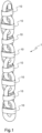
- FIG. 1 shows a 1 mesh which can be used for an item of jewelry and/or jewelry, or leather goods, textiles, cosmetics or even furniture.
- the snail 1 shown in the Figure 1 can for example be used to form a portion of a necklace chain or a bracelet.
- the mesh 1 comprises several links 10 assembled and secured to each other.
- the mesh 1 comprises one or more links 10 of the type described below, which can be assembled and secured to each other and/or to other links of the same or different type.
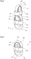
- FIG. 2 shows two links 10 of such a mesh 1, which are assembled and secured to each other.
- the mesh 1 is formed by successively assembling two by two several links 10 which are made in two parts, and the assembly of which forms a closed link 10.
- the links 10 of the mesh 1 each comprise a main body 100, which is here a male part of the link 10, and a closing cap 200, which is here a female part of the link 10.
- the main body 100 and the closing cap are removable and distinct from each other, and together form a closed link 10 when assembled.
- the main body 100 and the closure cap 200 may be made from separate materials.
- one of the main body 100 and the closure cap 200 preferably the main body 100, is made of metal, for example steel or brass, and the other, preferably the closure cap 200, is made of ceramic.
- the resulting link 10 is thus a two-material link.
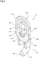
- FIG. 3 shows a link 10 taken in isolation and the Figure 4 shows this same link but in a state in which the main body 100 and the closing cap 200 are disassembled.
- the main body 100 comprises a base portion 110 having an enlarged section, for example of circular shape.
- the main body 100 also includes a head portion 120 having a reduced section relative to the enlarged section of the base portion 110, and which extends from the base portion 110.
- the reduced section of the head portion 120 is here semi-circular in shape.
- the base portion 110 and the head portion 120 are of a single piece.
- the main body 100 further comprises an insertion slot 130 formed in the head portion 120.
- the insertion slot 130 is configured so as to allow the passage of another link (similar to link 10 or not) of the plurality of links of the mesh 1, or even of a clasp in particular as will be described in the remainder of this document.
- the insertion slot 130 has dimensions which allow the passage of another link of the plurality of links.
- the base portion 110 has a generally U-shape.
- the base portion 110 comprises a first end at a first branch of the U-shape, which is here a first free end 111 of the main body 100.
- the head portion 120 also has a generally U-shape here.
- the head portion 120 comprises a first end at a first branch of the U-shape, which is here a second free end 121 of the main body 100.
- the first free end 111 and the second free end 121 are opposite and at a distance from each other, the space between the first free end 111 and the second free end 121 defining the insertion slot 130.
- the head portion 120 has a longer branch and a shorter branch, the shorter branch being the one comprising the second free end 121 of the main body 100.
- the head portion 120 comprises an elongated portion 125 forming the longer branch of the U-shape, and which faces the insertion slot 130.
- the head portion 120 has a convex side 123 oriented towards the inside of the link 10, and a flat side 124 oriented towards the outside of the link 10.
- the base portion 110 and the head portion 120 are here flush with the inside of the link 10.
- the main body 100 Due to the difference in section between the base portion 110 and the head portion 120, the main body 100 has a shoulder 101 formed at the junction of the base portion 110 and the head portion 120, on the outside of the link 10.
- the closure cap 200 comprises an arc-shaped arch portion 210 having two ends 213 and 214, and a strapping portion 220 connecting the ends 213 and 214 of the arch portion 210.
- the strapping portion 220 is substantially oblong in shape, and is connected at two junction zones 222 and 223 to the ends 213 and 214 of the arch portion 210.
- the arch portion 210 and the hoop portion 220 are here in one piece.
- the closing cap 200 thus comprises a wall which is perforated, formed by the arch portion 210 and the hoop portion 220.
- the arc shape of the vault portion 210 corresponds substantially to a U shape, and has for example a substantially constant semi-circular section.
- the strapping portion 220 delimits an introduction opening 221 of the closing cap 200, which opens into the internal space 201.
- the insertion opening 221 is of substantially rectangular shape, and is configured to be able to be introduced onto the head portion 120 of the main body 100.
- the strapping portion 220 has a height, i.e. a dimension in a direction transverse to the plane in which the strapping portion 220 extends, substantially equal to or greater than the height of the insertion slot. 130, that is to say the distance between the first free end 111 and the second free end 121 of the main body 100.
- the arch portion 210 has a convex side 211 facing the outside of the link 10, and a flat side 212 facing the inside of the link 10.
- the semi-circular section of the arch portion 210 of the closing cap 200 and the semi-circular section of the head portion 120 of the main body 100 are of complementary shapes so as to together form a circular section equivalent to the circular section of the base portion 110 of the main body 100.
- the arch portion 210 is configured to rest on the head portion 120 of the main body 100.
- the flat side 212 of the arch portion 210 and the flat side 124 of the head portion 120 come into contact substantially over their entire surface.
- the head portion 120 forms a stop for the arch portion 210, the closing cap 200 thus covering the head portion 120.
- the assembled link 10 Due to the complementary shape of the sections of the head portion 120 of the main body 100 and the arch portion 210 of the closing cap 200, the assembled link 10 has the shape of a closed link, as if it were made from a single piece.
- the strapping portion 220 is located substantially halfway up the link 10 when the main body 100 and the closing cap 200 are assembled, so that the closed link 10 is substantially symmetrical on either side of the strapping portion 220.
- the strapping portion 220 covers the insertion slot 130, as well as the elongated portion 125 of the main body 100, so as to close the insertion slot 130 and close the link 10.
- the strapping portion 220 which surrounds the closed link which results from the assembly of the main body 100 and the closing cap 200, delimits two internal spaces of the link 10 located on either side of the strapping portion 220.
- a first internal space corresponds to the internal space 201 of the closing cap 200, in which the head portion 120 of the main body 100 is housed at least in part when the main body 100 and the closing cap 200 are assembled.
- a second internal space 102 is delimited by the base portion 110 of the main body 100 and the strapping portion 220.
- the link 10 which is formed is a link of a marine type mesh, and in which the two internal spaces 201 and 102 communicate via the introduction opening 221.
- Each of the first internal space 201 and second internal space 102 is adapted to receive, simultaneously or not, a portion of another link secured to the link 10.
- Receiving a portion of another link in the first internal space 201 has the effect of locking the link 10 in its assembled state.
- this portion of the other link for example the base portion 110 when the other link is a similar link 10, is both in abutment against the convex side 123 of the head portion 120 of the main body 100, and against the strapping portion 220 of the closing cap 200.
- the closing cap 200 cannot be removed from the main body 100, and vice versa, i.e. the link 10 is maintained in an assembled state.
- the mesh 1 is thus formed by successive assembly of links 10 maintaining themselves in an assembled state by simple complementarity of shape.
- the dimensions of the internal spaces 201 and 102 are such that they allow a portion of another link to be accommodated without play or almost without play, so as to minimize the relative movements between the main body 100 and the closing cap 200 when they are assembled in a mesh.
- the first link 10 comprises its main body 100 and its closing cap 200 which are assembled.
- the first link 10 is thus closed, and its insertion slot 130 is closed because it is covered by the strapping portion 220.
- the internal space 201 of the first link 10 is arranged opposite the insertion slot 130 of the second link 10, or in other words the main body 100 of the second link 10 is arranged with its insertion slot 130 opposite the first link 10, at the level of the first internal space 201 of the first link 10.
- the insertion slot 130 of the second link 10 is arranged opposite the arch portion 210 of the closing cap 200 of the first link 10.
- the main body 100 of the first link 10 is inserted into the second link 10 through the insertion slot 130 of the second link 10, to a position in which the first free end 111 and the second free end 121 of the second link 10 are located opposite the internal space 201 of the first link 10.
- the second link 10 is inserted onto the first link 10 through the insertion slot of the second link 10.
- the first link 10 is moved in translation relative to the second link 10, so that the first free end 111 of the second link 10 passes through the first internal space 201 of the first link 10.
- the main body 100 of the second link 10 and the first link 10 are in an intermediate position in which they are moved in rotation relative to each other so as to be aligned, that is to say until reaching the position of the Figure 10 on which the first link 10 is received by its first internal space 201 on the base portion 110 of the second link 10, the first link 10 and the second link 10 then being aligned and at right angles to each other in their direction of alignment.
- the closing cap 200 of the second link 10 is arranged with its insertion opening 221 facing the head portion 120 of the second link 10.
- the closing cap 200 of the second link 10 is then inserted onto the head portion 120 of the second link 10 to together form the assembled second link 10, as shown in the Figure 2 . In this way, the first link 10 is mechanically secured to the second link 10.
- the first link 10 is maintained in its assembled state.
- a third link 10 may be secured to the second link 10 in a similar manner, in order to maintain the second link 10 in its assembled state.
- the preceding description of the assembly of two links 10 can be repeated for the assembly of other links, for example to obtain the meshing 1 of the Figure 1 and in particular here to form a chain for example of an item of jewelry and/or jewelry.
- the last link 10 of a mesh can be maintained in its assembled state by means of a part different from a link 10, and itself not requiring another link 10 for its locking.
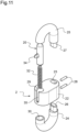
- it may be a clasp 2 adapted to link 10, as shown in the figures 11 And 12 .
- such a clasp 2 can also be used to close a chain formed by the mesh 1.
- the clasp 2 comprises a main part 21 and a movable part 20, mechanically secured to the main part 21 while being movable relative to the latter.
- the movable part 20 is movable in translation in the main part 21, between an open position and a closed position.
- the main part 21 comprises a central body 22, which is here generally cylindrical with an oblong base.
- the central body 22 comprises a first through opening 23 which crosses the height of the central body 22.
- the first through opening 23 is of oblong section.
- the main part 21 comprises a first portion 24 having a generally U-shape and a second portion 25 also having a generally U-shape.
- the first portion 24 comprises a tenon 26 at the end of a first branch of the U-shape.
- the second portion 25 also comprises a tenon 27 at the end of a first branch of the U-shape.
- the tenons 26 and 27 are of oblong section corresponding to the shape of the section of the first through opening 23.
- the tenons 26 and 27 of the first portion 24 and of the second portion 25 are inserted into the first through opening 23 respectively on either side of the central body 22.
- the main part 21 comprises two pins 28 which are inserted transversely into openings in the central body 22 and each of the tenons 26 and 27, in order to maintain the assembly of the central body 22 and the first portion 24 as well as the second portion 25.
- the first portion 24 comprises two branches of the U-shape of substantially the same length, excluding the tenon 26, the second branch of the U-shape thus resting on the central body 22.
- the second portion 25 comprises a second branch of the U-shape which is of reduced length compared to the first branch of the U-shape, the second branch of the U-shape thus comprising a free end facing the central body 22.
- the movable part 20 is here formed by a bolt of generally circular cylindrical shape.
- the central body 22 comprises a second through opening 29, which is here cylindrical in shape, and in which the movable part 20 can slide.
- the end of the second branch of the U-shape of the first portion 24 comprises a blind opening 30, substantially coaxial with the second through opening 29 and in which the movable part 20 can also slide at least partially.
- the movable part 20 When the movable part 20 is in its closed position, it connects the free end of the second portion 25 and the central body 22, and then defines an internal space 31 closed with the second portion 25 and the central body 22, in which a link 10 can for example be received.
- the movable part 20 When the movable part 20 is in its open position, it is slid into the second through opening 29 and into the blind opening 30, and opens the internal space 31.
- the clasp formed by the main part 21 and the mobile part 20 generally has the shape of a link 10 as described above.
- the clasp 2 comprises a return element which is here a helical compression spring 32.
- the spring 32 rests on the one hand on the bottom of the blind opening 30.
- the movable part 20 further comprises a blind opening 33 which is open opposite the blind opening 30, and which comprises a bottom against which the spring 32 also rests.
- the mobile part 20 may comprise a gripping stud 34, projecting laterally from the mobile part 20.
- the central body 22 comprises a slot 35 in the wall separating the second through opening 29 from the exterior of the central body 22, so as to allow the passage of the gripping stud 34 when the movable part 20 slides.
- the main body 100 and the closing cap are made of different precious materials.
Landscapes
- Engineering & Computer Science (AREA)
- General Engineering & Computer Science (AREA)
- Mechanical Engineering (AREA)
- Health & Medical Sciences (AREA)
- General Health & Medical Sciences (AREA)
- Pediatric Medicine (AREA)
- Adornments (AREA)
Applications Claiming Priority (1)
| Application Number | Priority Date | Filing Date | Title |
|---|---|---|---|
| FR2306376A FR3150083B1 (fr) | 2023-06-20 | 2023-06-20 | Maillon d’un article, emmaillement comportant un tel maillon et article comprenant un tel emmaillement |
Publications (1)
| Publication Number | Publication Date |
|---|---|
| EP4523563A1 true EP4523563A1 (de) | 2025-03-19 |
Family
ID=88147155
Family Applications (1)
| Application Number | Title | Priority Date | Filing Date |
|---|---|---|---|
| EP24180286.7A Pending EP4523563A1 (de) | 2023-06-20 | 2024-06-05 | Kettenglied für einen artikel, kettel mit einem solchen glied und artikel mit einem solchen kettenglied |
Country Status (3)
| Country | Link |
|---|---|
| EP (1) | EP4523563A1 (de) |
| CN (1) | CN119157347A (de) |
| FR (1) | FR3150083B1 (de) |
Citations (3)
| Publication number | Priority date | Publication date | Assignee | Title |
|---|---|---|---|---|
| FR390245A (fr) * | 1907-12-23 | 1908-09-30 | Laure Legrand | Perfectionnements dans les pompes à vide ou aspiraMaillon démontable dit "maillon de secours" permettant d'opérer la jonction de deux chaines ou de dentes ux troncons de chaines |
| US5331802A (en) * | 1990-01-18 | 1994-07-26 | Simon Varley | Security chain made from a series of links |
| WO2023009704A1 (en) * | 2021-07-30 | 2023-02-02 | Cemayla, Llc | Jewelry link |
-
2023
- 2023-06-20 FR FR2306376A patent/FR3150083B1/fr active Active
-
2024
- 2024-06-05 EP EP24180286.7A patent/EP4523563A1/de active Pending
- 2024-06-19 CN CN202410788690.5A patent/CN119157347A/zh active Pending
Patent Citations (4)
| Publication number | Priority date | Publication date | Assignee | Title |
|---|---|---|---|---|
| FR390245A (fr) * | 1907-12-23 | 1908-09-30 | Laure Legrand | Perfectionnements dans les pompes à vide ou aspiraMaillon démontable dit "maillon de secours" permettant d'opérer la jonction de deux chaines ou de dentes ux troncons de chaines |
| US5331802A (en) * | 1990-01-18 | 1994-07-26 | Simon Varley | Security chain made from a series of links |
| EP0511249B1 (de) | 1990-01-18 | 1996-04-17 | VARLEY, Simon | Kette |
| WO2023009704A1 (en) * | 2021-07-30 | 2023-02-02 | Cemayla, Llc | Jewelry link |
Also Published As
| Publication number | Publication date |
|---|---|
| FR3150083B1 (fr) | 2025-05-09 |
| CN119157347A (zh) | 2024-12-20 |
| FR3150083A1 (fr) | 2024-12-27 |
Similar Documents
| Publication | Publication Date | Title |
|---|---|---|
| EP3756501B1 (de) | Befestigungsvorrichtung für armband | |
| EP0529168B1 (de) | Schmuckring mit einem drehbaren äusseren Ringteil und Verfahren für dessen Herstellung | |
| FR2767390A1 (fr) | Charniere a ressort pour monture de lunette | |
| EP0833579B1 (de) | armbandverschluss | |
| CH644505A5 (fr) | Fermoir permettant de regler la longueur d'un bracelet. | |
| EP3162241B1 (de) | Klappbarer verschluss für armband | |
| EP4302633A1 (de) | Kettel aus schmuckartikel und schmuckartikel mit einer solchen kette | |
| EP4073394A1 (de) | Vorrichtung für eine lösbare verbindung zwischen zwei komponenten | |
| EP3462969B1 (de) | Schmuckartikel mit mindestens zwei relativ zueinander drehbeweglichen teilen | |
| EP4523563A1 (de) | Kettenglied für einen artikel, kettel mit einem solchen glied und artikel mit einem solchen kettenglied | |
| EP2813156B1 (de) | Verschluss für Schmuckstück oder Uhrenarmband | |
| EP3941300B1 (de) | Schnalle für ein uhrenband oder armband | |
| FR2818089A1 (fr) | Boitier d'appareil electronique | |
| EP1247469B1 (de) | Verschluss für Armreif mit zwei Druckknöpfe welche Führingselemente aufweisen | |
| EP2315538A1 (de) | Schmuckanordnung aus mindestens drei miteinander verbundenen teilen | |
| EP1785784A2 (de) | Vorrichtung zur Verbindung eines Uhrarmbands | |
| EP1075198B1 (de) | Uhrarmband | |
| CH551771A (fr) | Parure. | |
| FR2582200A1 (fr) | Fermoir notamment pour article de bijouterie tel que chaine, bracelet | |
| FR2815609A1 (fr) | Recipient a couvercle | |
| EP4302637A2 (de) | Öffnungs- und schliessvorrichtung vom typ reissverschluss für einen artikel, insbesondere für lederwaren | |
| FR3156288A1 (fr) | Fermoir de bracelet de montre comportant un dispositif de réglage de la longueur dudit bracelet. | |
| EP4609746A1 (de) | Dehnbarer dekorativer artikel | |
| FR3133300A1 (fr) | Fermoir a boucle deployante | |
| CH719481B1 (fr) | Fermoir à boucle déployante |
Legal Events
| Date | Code | Title | Description |
|---|---|---|---|
| PUAI | Public reference made under article 153(3) epc to a published international application that has entered the european phase |
Free format text: ORIGINAL CODE: 0009012 |
|
| STAA | Information on the status of an ep patent application or granted ep patent |
Free format text: STATUS: THE APPLICATION HAS BEEN PUBLISHED |
|
| AK | Designated contracting states |
Kind code of ref document: A1 Designated state(s): AL AT BE BG CH CY CZ DE DK EE ES FI FR GB GR HR HU IE IS IT LI LT LU LV MC ME MK MT NL NO PL PT RO RS SE SI SK SM TR |
|
| P01 | Opt-out of the competence of the unified patent court (upc) registered |
Free format text: CASE NUMBER: APP_17465/2025 Effective date: 20250410 |
|
| STAA | Information on the status of an ep patent application or granted ep patent |
Free format text: STATUS: REQUEST FOR EXAMINATION WAS MADE |
|
| 17P | Request for examination filed |
Effective date: 20250902 |
|
| STAA | Information on the status of an ep patent application or granted ep patent |
Free format text: STATUS: EXAMINATION IS IN PROGRESS |