EP4523600A1 - Système de visualisation médicale - Google Patents
Système de visualisation médicale Download PDFInfo
- Publication number
- EP4523600A1 EP4523600A1 EP23197400.7A EP23197400A EP4523600A1 EP 4523600 A1 EP4523600 A1 EP 4523600A1 EP 23197400 A EP23197400 A EP 23197400A EP 4523600 A1 EP4523600 A1 EP 4523600A1
- Authority
- EP
- European Patent Office
- Prior art keywords
- coupling part
- component
- cable
- visualization system
- processing apparatus
- Prior art date
- Legal status (The legal status is an assumption and is not a legal conclusion. Google has not performed a legal analysis and makes no representation as to the accuracy of the status listed.)
- Pending
Links
Images





Classifications
-
- A—HUMAN NECESSITIES
- A61—MEDICAL OR VETERINARY SCIENCE; HYGIENE
- A61B—DIAGNOSIS; SURGERY; IDENTIFICATION
- A61B1/00—Instruments for performing medical examinations of the interior of cavities or tubes of the body by visual or photographical inspection, e.g. endoscopes; Illuminating arrangements therefor
- A61B1/00002—Operational features of endoscopes
- A61B1/00043—Operational features of endoscopes provided with output arrangements
- A61B1/00045—Display arrangement
- A61B1/00048—Constructional features of the display
-
- A—HUMAN NECESSITIES
- A61—MEDICAL OR VETERINARY SCIENCE; HYGIENE
- A61B—DIAGNOSIS; SURGERY; IDENTIFICATION
- A61B1/00—Instruments for performing medical examinations of the interior of cavities or tubes of the body by visual or photographical inspection, e.g. endoscopes; Illuminating arrangements therefor
- A61B1/00002—Operational features of endoscopes
- A61B1/00004—Operational features of endoscopes characterised by electronic signal processing
- A61B1/00009—Operational features of endoscopes characterised by electronic signal processing of image signals during a use of endoscope
-
- A—HUMAN NECESSITIES
- A61—MEDICAL OR VETERINARY SCIENCE; HYGIENE
- A61B—DIAGNOSIS; SURGERY; IDENTIFICATION
- A61B1/00—Instruments for performing medical examinations of the interior of cavities or tubes of the body by visual or photographical inspection, e.g. endoscopes; Illuminating arrangements therefor
- A61B1/00002—Operational features of endoscopes
- A61B1/00011—Operational features of endoscopes characterised by signal transmission
- A61B1/00018—Operational features of endoscopes characterised by signal transmission using electrical cables
-
- A—HUMAN NECESSITIES
- A61—MEDICAL OR VETERINARY SCIENCE; HYGIENE
- A61B—DIAGNOSIS; SURGERY; IDENTIFICATION
- A61B1/00—Instruments for performing medical examinations of the interior of cavities or tubes of the body by visual or photographical inspection, e.g. endoscopes; Illuminating arrangements therefor
- A61B1/00064—Constructional details of the endoscope body
- A61B1/00066—Proximal part of endoscope body, e.g. handles
-
- A—HUMAN NECESSITIES
- A61—MEDICAL OR VETERINARY SCIENCE; HYGIENE
- A61B—DIAGNOSIS; SURGERY; IDENTIFICATION
- A61B1/00—Instruments for performing medical examinations of the interior of cavities or tubes of the body by visual or photographical inspection, e.g. endoscopes; Illuminating arrangements therefor
- A61B1/00064—Constructional details of the endoscope body
- A61B1/00105—Constructional details of the endoscope body characterised by modular construction
-
- A—HUMAN NECESSITIES
- A61—MEDICAL OR VETERINARY SCIENCE; HYGIENE
- A61B—DIAGNOSIS; SURGERY; IDENTIFICATION
- A61B1/00—Instruments for performing medical examinations of the interior of cavities or tubes of the body by visual or photographical inspection, e.g. endoscopes; Illuminating arrangements therefor
- A61B1/00112—Connection or coupling means
- A61B1/00114—Electrical cables in or with an endoscope
-
- A—HUMAN NECESSITIES
- A61—MEDICAL OR VETERINARY SCIENCE; HYGIENE
- A61B—DIAGNOSIS; SURGERY; IDENTIFICATION
- A61B1/00—Instruments for performing medical examinations of the interior of cavities or tubes of the body by visual or photographical inspection, e.g. endoscopes; Illuminating arrangements therefor
- A61B1/00112—Connection or coupling means
- A61B1/00121—Connectors, fasteners and adapters, e.g. on the endoscope handle
- A61B1/00124—Connectors, fasteners and adapters, e.g. on the endoscope handle electrical, e.g. electrical plug-and-socket connection
-
- A—HUMAN NECESSITIES
- A61—MEDICAL OR VETERINARY SCIENCE; HYGIENE
- A61B—DIAGNOSIS; SURGERY; IDENTIFICATION
- A61B1/00—Instruments for performing medical examinations of the interior of cavities or tubes of the body by visual or photographical inspection, e.g. endoscopes; Illuminating arrangements therefor
- A61B1/00112—Connection or coupling means
- A61B1/00121—Connectors, fasteners and adapters, e.g. on the endoscope handle
- A61B1/00128—Connectors, fasteners and adapters, e.g. on the endoscope handle mechanical, e.g. for tubes or pipes
-
- A—HUMAN NECESSITIES
- A61—MEDICAL OR VETERINARY SCIENCE; HYGIENE
- A61B—DIAGNOSIS; SURGERY; IDENTIFICATION
- A61B1/00—Instruments for performing medical examinations of the interior of cavities or tubes of the body by visual or photographical inspection, e.g. endoscopes; Illuminating arrangements therefor
- A61B1/04—Instruments for performing medical examinations of the interior of cavities or tubes of the body by visual or photographical inspection, e.g. endoscopes; Illuminating arrangements therefor combined with photographic or television appliances
- A61B1/05—Instruments for performing medical examinations of the interior of cavities or tubes of the body by visual or photographical inspection, e.g. endoscopes; Illuminating arrangements therefor combined with photographic or television appliances characterised by the image sensor, e.g. camera, being in the distal end portion
-
- A—HUMAN NECESSITIES
- A61—MEDICAL OR VETERINARY SCIENCE; HYGIENE
- A61B—DIAGNOSIS; SURGERY; IDENTIFICATION
- A61B1/00—Instruments for performing medical examinations of the interior of cavities or tubes of the body by visual or photographical inspection, e.g. endoscopes; Illuminating arrangements therefor
- A61B1/00064—Constructional details of the endoscope body
- A61B1/00103—Constructional details of the endoscope body designed for single use
Definitions
- the present disclosure relates to a medical visualization system and elements thereof.
- a medical visualization system comprising a medical visualization device, such as an endoscope, and a video processing apparatus.
- An endoscope may be utilized to visually examine certain areas of the body of a person, such as inside a body cavity of the person.
- an endoscope may be used to inspect the airways, the digestive tract, or the intestines.
- An endoscope may be provided with a camera and be attached to a video processing apparatus, such as a video processing apparatus with a display screen, a video output from the camera of the endoscope may be received and displayed at the video processing apparatus or a coupled display screen, thereby allowing an operator to control the endoscope to inspect an area of interest.
- a video processing apparatus such as a video processing apparatus with a display screen
- An endoscope may comprise an operating handle at a proximal end and an insertion cord extending from the handle towards a distal end.
- the handle is configured to be held by an operator and inter alia comprises externally protruding operating members connected to internal control means allowing the operator to control the movement of a bending section near the distal end of the insertion cord, while advancing the distal end of the insertion cord to a desired location, e.g. within a body cavity of a person.
- a coupled video processing apparatus such as a video processing apparatus with a display screen
- the location to which the distal end has been advanced may be inspected using the endoscope.
- the endoscope may be a laryngoscope, which is a more rigid type of endoscope, usually having an L-shape, used to inspect the larynx.
- the transmission component may comprise a component processor.
- the component processor may be adapted to receive the image data from the camera module.
- the component processor may be further adapted to preprocess the image data to provide the data representative of the image data, which may be received by the video processing apparatus, such as the processor of the video processing apparatus.
- the transmission component may transmit the data representative of the image data to the video processing apparatus, such as to the processor of the video processing apparatus.
- the endoscope 200 may be disposable, e.g. single use. Conversely, the transmission component 100 may be reusable. Thus, the transmission component 100 may be adapted to be coupled to a plurality of endoscopes, such as a plurality of different types of endoscopes, e.g. including bronchoscopes, laryngoscopes, duodenoscopes, urology endoscopes etc.
- endoscopes such as a plurality of different types of endoscopes, e.g. including bronchoscopes, laryngoscopes, duodenoscopes, urology endoscopes etc.
- Fig. 1b is a block diagram schematically illustrating an exemplary video processing apparatus 20, such as the video processing apparatus 20 of Fig. 1a .
- the video processing apparatus 20 comprises a processor 23 adapted to receive the image data and/or data representative of the image data, e.g. via the connection port 24, as explained above.
- the processor 23 is further adapted to cause a display, e.g. the optional display 21 of the video processing apparatus 20, to display a live representation of the image data.
- the video processing apparatus 20 may also or alternatively comprise an apparatus wireless transceiver 25. Accordingly, the processor 23 may be adapted to receive the image data and/or data representative of the image data via the apparatus wireless transceiver 25, which will be explained in further detail below.
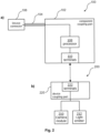
- Fig. 2a is a block diagram schematically illustrating an exemplary transmission component 100, with a component coupling part 102, a device cable 104, and a device connector 106.
- Fig. 2b is a block diagram schematically illustrating an exemplary endoscope 200 with a camera module 210 and an optional light emitter 212.
- the transmission component 100 comprises a component processor 108, which is adapted to receive the image data from the camera module 210 and preprocess the image data to provide data representative of the image data, which may then be transmitted to the video processing apparatus, e.g. via the device cable 104 and the device connector 106.
- the component coupling part 102 may comprise the component processor 108, as illustrated.
- the transmission component 100 comprises one or more component terminals 110 adapted to connect to one or more device terminals 222 of the device coupling part 220 when the component coupling part 102 is coupled with the device coupling part 220.
- the component coupling part 102 may comprise the one or more component terminals 110.
- the component terminals 110 may form an electrical connection between the transmission component 100 and the endoscope 200, such as between the component coupling part 102 and the device coupling part 220.
- the component terminals 110 may be connected with the component processor 108 and may facilitate an electrical connection between the component processor 108 and the camera module 210 of the endoscope, i.e. facilitating the receipt of the image data generated by the camera module 210.
- the endoscope 200 may be the endoscope 200 as illustrated in Fig. 1a .
- the endoscope 200 comprises a device coupling part 220.
- the device coupling part 220 is adapted to be coupled with the component coupling part 102.
- the device coupling part 220 comprises one or more device terminals 222 electrically connected to the camera module 210 and optionally to the light emitter 212.
- the device terminals 222 may facilitate an electrical connection between the component processor 108 of the transmission component 100 and the camera module 210, i.e. facilitating the transmission of the image data generated by the camera module 210.
- the transmission component 100 may facilitate transmission of data and/or signals from the video processing apparatus to the endoscope 200, such as to the camera module 210 and/or the light emitter 212.
- camera configuration data may be transmitted from the video processing apparatus to the endoscope 200 / camera module 210, e.g. via the transmission component 100, such as via the device connector 106, the device cable 104 and the component coupling part 102.
- Fig. 3a is a block diagram schematically illustrating an exemplary transmission component 100 with a component coupling part 102.
- the transmission component 100 of Fig. 3a comprises a device wireless transceiver 112.
- Fig. 3b corresponds to Fig. 2b .
- the device wireless transceiver 112 is adapted to wirelessly communicate with an apparatus wireless transceiver 25 of the video processing apparatus 20, such as the video processing apparatus 20 as illustrated in Fig. 1a .
- the apparatus wireless transceiver 25 may be an integrated element of the video processing apparatus 20.
- the apparatus wireless transceiver 25 may be connected to the video processing apparatus, in a similar way as the device connector 106, as illustrated in Fig. 1a .
- the device wireless transceiver 112 is adapted to wirelessly transmit the image data and/or the data representative of the image data to the video processing apparatus 20, e.g. to the apparatus wireless transceiver 25 of the video processing apparatus 20.
- a "transceiver” is meant as being either or both of a transmitter and a receiver.
- the device wireless transceiver 112 may be a transmitter and the apparatus wireless transceiver 25 may be a receiver.
- the device wireless transceiver 112 comprises both a transmitter and a receiver and/or the apparatus wireless transceiver 25 comprises both a transmitter and a receiver.
- the transmission component 100 may, also in the present example, comprise a wireless transceiver 112 and facilitate transmission of data and/or signals from the video processing apparatus to the endoscope 200, such as to the camera module 210 and/or the light emitter 212.
- camera configuration data may be transmitted from the video processing apparatus to the endoscope 200 / camera module 210, e.g. via the transmission component 100, such as via the device wireless transceiver 112.
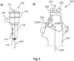
- Fig. 4 schematically illustrates an exemplary component coupling part 102 of an exemplary transmission component 100 ( Fig. 4a ) and an exemplary device coupling part 220 of an exemplary endoscope 200 ( Fig. 4b ).
- an outer shell part of the endoscope 200 is removed to show some internal parts of the device coupling part 220.
- the component coupling part 102 has a primary coupling element 118.
- the primary coupling element is elongated and extends along a coupling part axis AxC.
- the device coupling part 220 has a secondary coupling element 226.
- the secondary coupling element 226 forms a cavity adapted to receive the primary coupling element 118.
- the handle 202 is an elongate element extending along the handle axis AxH.
- the cavity of the secondary coupling element 226 may extend along a handle axis AxH of the handle 202.
- the device coupling part 220 comprises a twist lock 228.
- the twist lock is adapted to engage by rotation of the handle 202, e.g. around the coupling part axis AxC and/or the handle axis AxH, with a protruding element of the component coupling part 102, e.g. of the primary coupling element 118, when the primary coupling element 118 is fully received by the secondary coupling element 226.
- the protruding element engaging with the twist lock may be a part of the device cable 104
- the component coupling part 102 may comprise one or more physical activatable input mechanisms 114.
- Activation of the one or more physical activatable input mechanisms 114 may cause the transmission component 100 to transmit one or more input mechanism signals to the video processing apparatus indicative of activation of the one or more physical activatable input mechanisms 114.
- a user may activate a function of the video processing apparatus 20 (see Fig. 1a ) by activation of one of the physical activatable input mechanisms 114.
- a physical activatable input mechanism 114 may be a button, e.g. a button directly depressible by the user, such as the top part of the component coupling part 102.
- a physical activatable input mechanisms 114 may be a lever, a switch or similar.
- the one or more physical activatable input mechanisms 114 may be provided on a part received by the device coupling part 220, when the component coupling part 102 is connected with the device coupling part 220.
- the handle 202 of the endoscope 4, such as the device coupling part 220, comprises one or more communicator elements 224.
- the one or more communicator elements 224 may be plungers, levers etc.
- the one or more communicator elements 224 is adapted to activate the one or more physical activatable input mechanisms 114, when being manipulated by a user.
- the communicator elements 224 may extend from a first side 224A exteriorly of the handle 202 to a second side 224B interiorly of the handle 202.
- the second side 224B is adapted to contact a respective physical activatable input mechanism of the one or more physical activatable input mechanisms 114.
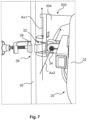
- Figs 5a-d schematically illustrate an exemplary transmission component 100 with a component coupling part 102 and an exemplary endoscope 200 with a device coupling part 220.
- Figs. 5a-d further illustrate an exemplary connection between the component coupling part 102 and the device coupling part 220.
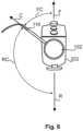
- the device cable 104 comprises a stiffened portion 116 extending from the second cable end 104B.
- the stiffened portion may be substantially straight. Alternatively, the stiffened portion may be curved either upwards and/or away from the operator.
- the stiffened portion 116 of the device cable 104 may extend in a certain direction relative to the handle 202, such as relative to the handle axis AxH.
- the stiffened portion 116 of the device cable 104 may extend in a normal plane Pn normal to the handle axis AxH, as illustrated.
- the stiffened portion 116 may extend at an angle relative to the normal plane Pn normal to the handle axis AxH, and/or the stiffened portion 116 may be curved upwards or downwards. In such examples, the stiffened portion 116 may extend between an upper plane Pu and a lower plane PI.
- the upper plane Pu may form an angle of less than 15 degrees, e.g. +15 degrees, e.g. between 0 and 15 degrees, relative to the normal plane Pn.
- the lower plane PI may form an angle of less than 15 degrees, e.g. -15 degrees, e.g. between -15 and 0 degrees, relative to the normal plane Pn.
- the lower plane PI may form an angle of 30 degrees relative to the upper plane Pu.
- the lower plane PI, the upper plane Pu and the normal plane Pn may intersect the handle axis AxH at the same point.
- the handle 202 is adapted to be gripped by a first hand 4 of an operator such that a back side 202B of the handle 202 is facing in a backwards direction R towards the wrist of the first hand 4 and a front side 202A is facing in a forward direction F opposite the backward direction R.
- the first hand may be a left hand or a right hand.
- the figures show a right hand gripping the handle 202, although it may be more customary to grip an endoscope with the left hand.
Landscapes
- Health & Medical Sciences (AREA)
- Life Sciences & Earth Sciences (AREA)
- Surgery (AREA)
- Engineering & Computer Science (AREA)
- Biomedical Technology (AREA)
- Molecular Biology (AREA)
- Pathology (AREA)
- Radiology & Medical Imaging (AREA)
- Nuclear Medicine, Radiotherapy & Molecular Imaging (AREA)
- Biophysics (AREA)
- Physics & Mathematics (AREA)
- Heart & Thoracic Surgery (AREA)
- Medical Informatics (AREA)
- Optics & Photonics (AREA)
- Animal Behavior & Ethology (AREA)
- General Health & Medical Sciences (AREA)
- Public Health (AREA)
- Veterinary Medicine (AREA)
- Signal Processing (AREA)
- Mechanical Engineering (AREA)
- Endoscopes (AREA)
Priority Applications (2)
| Application Number | Priority Date | Filing Date | Title |
|---|---|---|---|
| EP23197400.7A EP4523600A1 (fr) | 2023-09-14 | 2023-09-14 | Système de visualisation médicale |
| US18/883,345 US20250089991A1 (en) | 2023-09-14 | 2024-09-12 | Medical visualization system |
Applications Claiming Priority (1)
| Application Number | Priority Date | Filing Date | Title |
|---|---|---|---|
| EP23197400.7A EP4523600A1 (fr) | 2023-09-14 | 2023-09-14 | Système de visualisation médicale |
Publications (1)
| Publication Number | Publication Date |
|---|---|
| EP4523600A1 true EP4523600A1 (fr) | 2025-03-19 |
Family
ID=88068621
Family Applications (1)
| Application Number | Title | Priority Date | Filing Date |
|---|---|---|---|
| EP23197400.7A Pending EP4523600A1 (fr) | 2023-09-14 | 2023-09-14 | Système de visualisation médicale |
Country Status (2)
| Country | Link |
|---|---|
| US (1) | US20250089991A1 (fr) |
| EP (1) | EP4523600A1 (fr) |
Citations (4)
| Publication number | Priority date | Publication date | Assignee | Title |
|---|---|---|---|---|
| US20170215695A1 (en) * | 2016-01-29 | 2017-08-03 | Boston Scientific Scimed, Inc. | Medical instrument system |
| WO2020006517A1 (fr) * | 2018-06-28 | 2020-01-02 | Meditrina, Inc. | Endoscope et procédé d'utilisation |
| WO2021090056A1 (fr) * | 2019-11-08 | 2021-05-14 | Suzhou Acuvu Med Tech Co Ltd | Ultrasons et endoscopie combinés |
| WO2021242736A1 (fr) * | 2020-05-29 | 2021-12-02 | Noah Medical Corporation | Procédés et systèmes pour endoscope jetable |
Family Cites Families (5)
| Publication number | Priority date | Publication date | Assignee | Title |
|---|---|---|---|---|
| CA2938993A1 (fr) * | 2014-02-06 | 2015-08-13 | Dentsply International Inc. | Controle de racines dentaires et de l'espace de la cavite endodontique a l'interieur de celles-ci |
| CN108697317B (zh) * | 2016-01-07 | 2021-10-08 | 格伦·P·加德纳 | 气管内导管插入装置 |
| US10835115B2 (en) * | 2017-11-15 | 2020-11-17 | Aircraft Medical Ltd. | Multifunctional visualization instrument |
| US11696671B2 (en) * | 2019-08-19 | 2023-07-11 | Covidien Ag | Steerable endoscope with motion alignment |
| US20240090922A1 (en) * | 2021-05-05 | 2024-03-21 | Intravu Inc. | Miniature Angle-View Endoscope with Image Orientation Correction |
-
2023
- 2023-09-14 EP EP23197400.7A patent/EP4523600A1/fr active Pending
-
2024
- 2024-09-12 US US18/883,345 patent/US20250089991A1/en active Pending
Patent Citations (4)
| Publication number | Priority date | Publication date | Assignee | Title |
|---|---|---|---|---|
| US20170215695A1 (en) * | 2016-01-29 | 2017-08-03 | Boston Scientific Scimed, Inc. | Medical instrument system |
| WO2020006517A1 (fr) * | 2018-06-28 | 2020-01-02 | Meditrina, Inc. | Endoscope et procédé d'utilisation |
| WO2021090056A1 (fr) * | 2019-11-08 | 2021-05-14 | Suzhou Acuvu Med Tech Co Ltd | Ultrasons et endoscopie combinés |
| WO2021242736A1 (fr) * | 2020-05-29 | 2021-12-02 | Noah Medical Corporation | Procédés et systèmes pour endoscope jetable |
Also Published As
| Publication number | Publication date |
|---|---|
| US20250089991A1 (en) | 2025-03-20 |
Similar Documents
| Publication | Publication Date | Title |
|---|---|---|
| CN108135447B (zh) | 带有可摇摄相机的内窥镜及相关方法 | |
| JP5117263B2 (ja) | 内視鏡システム | |
| US8100825B2 (en) | Endoscope and supportive member for bending operation of the same | |
| EP1900318A1 (fr) | Endoscope et système endoscopique | |
| US20120078050A1 (en) | Endotracheal intubation device | |
| US11998178B2 (en) | Video laryngoscope and method for using same | |
| EP2190341A2 (fr) | Système d'endoscope | |
| JP2005279253A (ja) | 内視鏡 | |
| US20140155696A1 (en) | Endoscope | |
| CN109922705A (zh) | 内窥镜、内窥镜的线材安装方法以及内窥镜的线材拆卸方法 | |
| WO2005110192A1 (fr) | Dispositif d'insertion | |
| US20250194915A1 (en) | Medical visualisation device | |
| US20240090753A1 (en) | Endoscope system | |
| US20250089991A1 (en) | Medical visualization system | |
| CN112470056B (zh) | 内窥镜用处理器以及内窥镜系统 | |
| US20230172433A1 (en) | Modular endoscope with a bayonet connection | |
| JP2011152192A (ja) | 内視鏡 | |
| JP4005088B2 (ja) | 内視鏡 | |
| JP3662086B2 (ja) | 内視鏡 | |
| US20250194902A1 (en) | Relay adapter and medical apparatus system | |
| JP2020500617A (ja) | 携帯型内視鏡 | |
| JP2009183333A (ja) | 検診用内視鏡 | |
| JP2001000386A (ja) | 内視鏡装置 | |
| US20170196434A1 (en) | Insertion instrument and insertion device | |
| JP2004194916A (ja) | 内視鏡システム収納ケース |
Legal Events
| Date | Code | Title | Description |
|---|---|---|---|
| PUAI | Public reference made under article 153(3) epc to a published international application that has entered the european phase |
Free format text: ORIGINAL CODE: 0009012 |
|
| STAA | Information on the status of an ep patent application or granted ep patent |
Free format text: STATUS: THE APPLICATION HAS BEEN PUBLISHED |
|
| AK | Designated contracting states |
Kind code of ref document: A1 Designated state(s): AL AT BE BG CH CY CZ DE DK EE ES FI FR GB GR HR HU IE IS IT LI LT LU LV MC ME MK MT NL NO PL PT RO RS SE SI SK SM TR |
|
| STAA | Information on the status of an ep patent application or granted ep patent |
Free format text: STATUS: REQUEST FOR EXAMINATION WAS MADE |
|
| 17P | Request for examination filed |
Effective date: 20250820 |
|
| TPAC | Observations filed by third parties |
Free format text: ORIGINAL CODE: EPIDOSNTIPA |
|
| GRAP | Despatch of communication of intention to grant a patent |
Free format text: ORIGINAL CODE: EPIDOSNIGR1 |
|
| STAA | Information on the status of an ep patent application or granted ep patent |
Free format text: STATUS: GRANT OF PATENT IS INTENDED |