EP4523618A1 - System zur verarbeitung von positionssignalen - Google Patents
System zur verarbeitung von positionssignalen Download PDFInfo
- Publication number
- EP4523618A1 EP4523618A1 EP24200682.3A EP24200682A EP4523618A1 EP 4523618 A1 EP4523618 A1 EP 4523618A1 EP 24200682 A EP24200682 A EP 24200682A EP 4523618 A1 EP4523618 A1 EP 4523618A1
- Authority
- EP
- European Patent Office
- Prior art keywords
- clock
- signal
- rate
- processor
- signals
- Prior art date
- Legal status (The legal status is an assumption and is not a legal conclusion. Google has not performed a legal analysis and makes no representation as to the accuracy of the status listed.)
- Pending
Links
Images


Classifications
-
- A—HUMAN NECESSITIES
- A61—MEDICAL OR VETERINARY SCIENCE; HYGIENE
- A61B—DIAGNOSIS; SURGERY; IDENTIFICATION
- A61B5/00—Measuring for diagnostic purposes; Identification of persons
- A61B5/06—Devices, other than using radiation, for detecting or locating foreign bodies ; Determining position of diagnostic devices within or on the body of the patient
- A61B5/061—Determining position of a probe within the body employing means separate from the probe, e.g. sensing internal probe position employing impedance electrodes on the surface of the body
- A61B5/062—Determining position of a probe within the body employing means separate from the probe, e.g. sensing internal probe position employing impedance electrodes on the surface of the body using magnetic field
-
- A—HUMAN NECESSITIES
- A61—MEDICAL OR VETERINARY SCIENCE; HYGIENE
- A61B—DIAGNOSIS; SURGERY; IDENTIFICATION
- A61B5/00—Measuring for diagnostic purposes; Identification of persons
- A61B5/06—Devices, other than using radiation, for detecting or locating foreign bodies ; Determining position of diagnostic devices within or on the body of the patient
- A61B5/065—Determining position of the probe employing exclusively positioning means located on or in the probe, e.g. using position sensors arranged on the probe
-
- A—HUMAN NECESSITIES
- A61—MEDICAL OR VETERINARY SCIENCE; HYGIENE
- A61B—DIAGNOSIS; SURGERY; IDENTIFICATION
- A61B18/00—Surgical instruments, devices or methods for transferring non-mechanical forms of energy to or from the body
- A61B18/04—Surgical instruments, devices or methods for transferring non-mechanical forms of energy to or from the body by heating
- A61B18/12—Surgical instruments, devices or methods for transferring non-mechanical forms of energy to or from the body by heating by passing a current through the tissue to be heated, e.g. high-frequency current
- A61B18/14—Probes or electrodes therefor
- A61B18/1492—Probes or electrodes therefor having a flexible, catheter-like structure, e.g. for heart ablation
-
- A—HUMAN NECESSITIES
- A61—MEDICAL OR VETERINARY SCIENCE; HYGIENE
- A61B—DIAGNOSIS; SURGERY; IDENTIFICATION
- A61B34/00—Computer-aided surgery; Manipulators or robots specially adapted for use in surgery
- A61B34/20—Surgical navigation systems; Devices for tracking or guiding surgical instruments, e.g. for frameless stereotaxis
-
- A—HUMAN NECESSITIES
- A61—MEDICAL OR VETERINARY SCIENCE; HYGIENE
- A61B—DIAGNOSIS; SURGERY; IDENTIFICATION
- A61B5/00—Measuring for diagnostic purposes; Identification of persons
- A61B5/24—Detecting, measuring or recording bioelectric or biomagnetic signals of the body or parts thereof
- A61B5/25—Bioelectric electrodes therefor
- A61B5/279—Bioelectric electrodes therefor specially adapted for particular uses
- A61B5/28—Bioelectric electrodes therefor specially adapted for particular uses for electrocardiography [ECG]
- A61B5/283—Invasive
- A61B5/287—Holders for multiple electrodes, e.g. electrode catheters for electrophysiological study [EPS]
-
- A—HUMAN NECESSITIES
- A61—MEDICAL OR VETERINARY SCIENCE; HYGIENE
- A61B—DIAGNOSIS; SURGERY; IDENTIFICATION
- A61B5/00—Measuring for diagnostic purposes; Identification of persons
- A61B5/68—Arrangements of detecting, measuring or recording means, e.g. sensors, in relation to patient
- A61B5/6846—Arrangements of detecting, measuring or recording means, e.g. sensors, in relation to patient specially adapted to be brought in contact with an internal body part, i.e. invasive
- A61B5/6847—Arrangements of detecting, measuring or recording means, e.g. sensors, in relation to patient specially adapted to be brought in contact with an internal body part, i.e. invasive mounted on an invasive device
- A61B5/6852—Catheters
-
- A—HUMAN NECESSITIES
- A61—MEDICAL OR VETERINARY SCIENCE; HYGIENE
- A61M—DEVICES FOR INTRODUCING MEDIA INTO, OR ONTO, THE BODY; DEVICES FOR TRANSDUCING BODY MEDIA OR FOR TAKING MEDIA FROM THE BODY; DEVICES FOR PRODUCING OR ENDING SLEEP OR STUPOR
- A61M25/00—Catheters; Hollow probes
- A61M25/0067—Catheters; Hollow probes characterised by the distal end, e.g. tips
- A61M25/0082—Catheter tip comprising a tool
-
- A—HUMAN NECESSITIES
- A61—MEDICAL OR VETERINARY SCIENCE; HYGIENE
- A61B—DIAGNOSIS; SURGERY; IDENTIFICATION
- A61B34/00—Computer-aided surgery; Manipulators or robots specially adapted for use in surgery
- A61B34/20—Surgical navigation systems; Devices for tracking or guiding surgical instruments, e.g. for frameless stereotaxis
- A61B2034/2046—Tracking techniques
- A61B2034/2051—Electromagnetic tracking systems
Definitions
- the medical devices may be for example one or more catheters, and in many cases a single catheter includes a plurality of portions/sections, which may be for example one or more flexible sections (such as flexible arms/splines thereof) and/or medical instruments which may be distributed on the flexible sections (e.g., sensors/probs, electrodes such as EEG electrodes, ablation instruments and/or other instruments).
- the flexible sections of such catheters may be flexed/bent to simultaneously approach/contact different parts of the treated anatomy, for sensing (mapping) and/or treating the tissue at those different parts by the medical instruments thereon, in some case simultaneously.
- Diagnosis and treatment of cardiac arrhythmias include mapping the electrical properties of heart tissue, especially the endocardium and the heart volume, and selectively ablating cardiac tissue by application of energy.
- one or more catheters having a plurality of portions such as flexible sections/splines, are inserted into the patient body.
- medical instruments arranged on these plurality of portions are operated for carrying out multiple interrelated operations such as electrocardiogram (ECG) mapping, tissue ablation, temperature sensing/mapping and/or image/ultrasound sensing.
- ECG electrocardiogram
- modules/elements of the present invention are used to designate similar modules/elements of the present invention or elements/modules having like functionalities. Accordingly, unless otherwise specified, description of modules/elements with reference to a certain embodiment of the invention should be understood to apply to all embodiments of the present invention in which such module/element is incorporated.
- catheters such as intracardiac ECG mapping catheters and/or ablation catheters, having a plurality of distal end portions, such as movable/flexible sections (e.g., splines) and/or medical instruments are used.
- movable/flexible sections e.g., splines
- medical instruments are arranged at various movable/flexible sections of the catheter's distal tip, such as the shaft, distal end effector, splines and/or at various other sections of the distal end effector thereof.
- the movable/flexible sections of the catheter may be adapted for flexing/expanding during the medical procedure (e.g., in order to accommodate the volume of the treated/monitored body anatomy and/or for bringing medical instruments thereon into contact or close proximity, with the wall/boundary of the treated/monitored body anatomy.
- Such techniques are used for example in order to enable mapping and/or treating several tissue regions of the anatomy substantially simultaneously.
- a large number of medical instruments such as ECG electrodes, ablation utilities/instruments or other instruments, which may be arranged at a plurality of movable/flexible sections of a catheter, and may for example be used to enable a physician to simultaneously capture/map the electrical activity from multiple locations in the heart chamber, and/or or to simultaneously ablate specific tissue regions thereof.
- the positions of the medical instruments furnished at the different flexible/movable sections of the catheter, and/or the positions of one or more of the flexible/movable sections of the catheter themselves should be monitored/tracked relative to treated/probed anatomy of the patient's body.
- distal end portions of a medical device/catheter and variants thereof is used to designate portions/elements/sections that are arranged at a distal tip/end of a medical device/catheter, and whose positions should be determined during a medical procedure.
- distal end portions may encompasses any one of flexible/movable section(s) of a catheter's distal tip, and/or medical instruments arranged thereon, which are associated with position sensors located adjacent thereto and capable of providing data/signals indicative of the respective positions of the distal end portions.
- position is used herein to designate any one of a location, orientation or both, of a medical device or of a distal end portion thereof. For instance, in some case there may not be a need to determine the location of a medical-device or of portion thereof, but only its orientation, or vice- versa, and the system of the present invention may be adapted/operable to achieve the same.
- medical device/catheter may be configured such that different distal end portions thereof, or some of them, include respective position sensors capable of receiving location signals (e.g., electromagnetic signals) by which the positions of the different portions can be determined. These received location signals should then processed in order to monitor/track the positions of different portions of the catheter's distal end a during the medical procedure. Accordingly in this way valuable information about the positions of different portions of the medical device/catheter can be provided to the physician during the medical procedure (e.g., in real-time).
- location signals e.g., electromagnetic signals
- the conventional hardware typically includes transmitters for transmitting the location signals that can be received by the plurality position sensors of such catheters or other medical devices, but has limited channels for collecting the locations signals received by the plurality of position sensors of such devices, and cannot accommodate simultaneous processing of location signals provided from such pluralities of positions sensors that are embedded in some of the advanced medical devices, such as spline or basket type catheters which have a plurality of respectively movable portions at their distal end/tip.
- the present invention therefore provides novel systems and methods for solving these problems to enable extending the capabilities of existing medical device positioning hardware to enable determining (e.g., simultaneously), the positions of multiple portions of medical devices, while utilizing, and in synchronization with, location signals that are provided/transmitted by the existing conventional medical device positioning hardware.
- the invention facilitates the positioning of relatively large pluralities of position sensors which may not be facilitated by the conventional positioning hardware, while without a need to replace the existing positioning hardware (e.g., which may already be deployed) and without addition of location signal transmitters or transmission of additional location signal. Accordingly, the positions of large number of medical devices/instruments or portions thereof may be determined during a medical procedure in cost effective manner, and without overcrowding the medical facilities with additional electromagnetic signals.
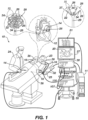
- System 10 includes or is connectable to multiple medical devices 14 and may include for example catheters 36 and 37 , whose positions, and preferably the positions of the various distal end portions 35 thereof, should be determined by the system 10. It should be noted that the distal end portions 35 whose positions are to be determined, a may include the main body (e.g. a catheter's shaft) 14H of a medical device 14 such as catheter 36 or 37 , and/or one or more flexible/movable sections/splines 22 thereof, and/or medical instruments 26 furnished at the distal end of the medical device 14 (e.g.
- the distal end portions 35 include some of the medical instruments 26 and/or the movable sections/splines 22 at which they are furnished in the catheters 36 and/or 37 .
- the movable sections 22 may be implemented using various configurations such as flexible splines as shown in the figure, or by other configurations for example utilizing pivots, flexible joints, extendable/telescopic shafts or any other configuration without departing from the scope of the present invention.
- Catheters 36 and/or 37 may be percutaneously inserted by a physician 24 through the patient's vascular system into a chamber or vascular structure of a heart 12 .
- a delivery sheath catheter is inserted into the left or right atrium near a desired location in heart 12 .
- one or more catheters, such as 36 and/or 37 may be inserted into the delivery sheath catheter so as to arrive at the desired location in heart 12 .
- the system 10 may include catheters dedicated for sensing Intracardiac Electrogram (IEGM) signals, such as catheter 37 , catheters dedicated for ablating, such as catheter 36 , catheters dedicated for both sensing and ablating (not specifically shown in the figure), and/or other medical devices.
- IEGM Intracardiac Electrogram
- catheters 37 and 36 which are configured for sensing IEGM and for ablating are respectively illustrated herein.
- Physician 24 may place a distal tip 28 of any of the catheters 14 such that multiple medical instruments 26 thereof, which are arranged on the flexible/movable sections 22 of the catheter 14 can move/flex to approach/contact the heart wall for probing/treating target sites in heart 12.
- physician 24 may place a distal end 28 of the respective sensing or ablation catheter, 37 or 36 , such that the medical instruments 26 thereof approach/contact with tissue at the target site.
- Catheters 36 and 37 shown in the figure exemplify medical devices 14 whose positions, and/or the positions of at least some distal end portions 35 thereof (e.g., medical instruments 26 and/or movable sections 22 ) should be determined (tracked/monitored) by the system 10 .
- Magnetic based position sensors 29 and/or 34 located on the catheter's distal tip 28 may be operated to provide data indicative of the real-time positions of the distal end portions 35 of the catheters during the medical procedure.
- the magnetic based position sensors 29 and 34 operate in conjunction with location pad 25 which includes a plurality of location signal transmitters 32 (e.g., magnetic coils) that generate/transmit electro-magnetic location signals (e.g., magnetic fields) in a predefined working volume surrounding the patient.
- location signal transmitters 32 e.g., magnetic coils
- electro-magnetic location signals e.g., magnetic fields
- Real time position of the distal tip 28 of the catheter 36 / 37 and/or of the distal end portions 35 thereof may then be tracked based on the electro-magnetic location signals that are generated with location pad 25 and sensed by magnetic based position sensor 29 and/or 34. Details of the magnetic based position sensing technology are described in U.S. Patent Nos.
- Catheters 36 and 37 shown in Fig. 1 exemplify medical devices 14 that are connectable to the system 10 and each includes multiple distal end portions 35 including in these examples flexible sections 22 (splines or basket arms) extending from the distal tips 28 of the catheters 36 and 37 and medical instruments 26 arranged thereon.
- Fig. 2 a perspective view of an ablation catheter 36 manifesting an example of a medical device 14 with movable distal end portions 35 is illustrated.
- the catheter 36 includes a shaft 14H having a distal end/tip 28.
- the catheter 36 in this non-limiting example includes a plurality of distal end portions 35 arranged at the distal end/tip 28 including flexible sections 22 (hereinafter also referred to as splines ) and multiple medical instruments 26 arranged thereon.
- the splines 22 arranged near/at the distal end 28 form and expandable distal end assembly that can be deflectable outwardly from the catheter by moving the pusher rode 14P to thereby engage the medical instruments 26 to approach/contact the tissue wall of the heart for ablation of desired regions of the tissue.
- medical instruments 26 may include for example near-field intracardial electrogram sensors/electrodes for sensing near-field signals IEGM signals (e.g., activation biopotential signals) when the catheter is located intracardially and the instruments 26 are approached to the tissue.
- IEGM signals e.g., activation biopotential signals
- the flexible sections 22 are connected to one another in a "basket" like form.
- the flexible sections 22 of the catheter may be connected to one another in a different configuration and/or may be independently movable such as in catheter 37 shown in Fig.1 , and/or may have different shapes/configurations (e.g., other than splines).
- the system of the present invention may be configured and operable for determining the position of a medical device(s) 14 connected thereto; e.g., catheter(s) 36 and/or 37 , and/or of distal end portions 35 thereof.
- the catheter for example 36, may include a plurality of position sensors e.g., 29 and 34 enabling the system the system 10 of the present invention to determine the positions of distal end portions 35.
- catheter 36 includes a position sensor 29 embedded in the main body of the catheter (e.g., in or near the distal tip 28 thereof) to enable tracking the location and/or orientation of distal tip 28 of the catheter 36.
- catheter 36 includes a plurality of position sensors 34 arranged at the movable sections 22 or other distal end portions 35 thereof and, whose positions can also be tracked by the system 10.
- the position sensors 29 and/or 34 are adapted to receive location signals that are transmitted by a location signal transmitter receiver utility of the system 10 , and to provide the received signals for processing by system 10.
- the location signals obtained from the position sensors 29 and/or 34 enable the system 10 to determine the respective positions of some or all of the distal end portions 35 of the catheter 36 , such as the positions of the flexible sections 22 thereof and/or the positions of medical instruments thereon 26 , as well as typically the position of the main-body/distal-tip 28 of the catheter 36.
- the system 10 may utilize the signals from the position sensors 34 to determine/assess the shape(s) of the distal end flexible sections 22 of the catheter while they being flexed/shifted during the medical procedure.
- the position sensors 29 and/or 34 are magnetic/electromagnetic based position sensors.
- the position sensors such as 29 may be implemented as a three axes sensor (TAS) including three magnetic coils to enable sensing of three-dimensional (3D) location and orientation thereof.
- the position sensors, such as 34 may be implemented as single-axis sensor (SAS) including one magnetic coil to enable axial sensing of their orientation (e.g., whereby the axial position sensing obtained by SAS sensors may be for instance combined with three-dimensional (3D) position and orientation sensing of another position sensor of the catheter, such as 29 , to facilitate determining the locations of the SAS sensors).
- SAS single-axis sensor
- the catheter 37 illustrated in Fig. 1 may in some cases have similar configuration as catheter 36 describe above, although the flexible sections 22 may be configured differently, e.g., not necessarily connected/constrained to one another in basket form.
- system 10 may also include one or more electrode patches 38 positioned for skin contact on patient 23 to establish location reference for location pad 25.
- one or more of the distal end portions 35 include ECG sensors/electrodes, and the location pad 25 may also be used for locating such distal end portions by impedance-based location tracking.
- Impedance-based location tracking may be used for example for locating distal end portions 35 that are not associated/fumished with position sensors capable of sensing their accurate positions, provided that the distal end portions 35 are furnished with electrodes suitable for determining their positions utilizing impedance-based tracking techniques.
- Electrodes e.g., ECG electrodes in case such are included at/on the distal end portion 35.
- the electrical current is then sensed at electrode skin patches 38 so that the location of each ECG electrode can be triangulated via the electrode patches 38. Details of the impedance-based location tracking technology are described in US Patent Nos. 7,536,218 ; 7,756,576 ; 7,848,787 ; 7,869,865 ; and 8,456,182 .
- System 10 may also include a recorder 11 records and displays electrograms 21 captured with body surface electrocardiogram (ECG) electrodes 18 and intracardiac electrograms (IEGM) captured with ECG electrodes of one of the medical devices/catheters 14 which may be connected to the system.
- Recorder 11 may include pacing capability for pacing the heart rhythm and/or may be electrically connected to a standalone pacer.
- System 10 may include an ablation energy generator 50 that is adapted to conduct ablative energy to one or more of electrodes at a distal tip of one of the catheters 14 that configured for ablating.
- Energy produced by ablation energy generator 50 may include, but is not limited to, radiofrequency (RF) energy or pulsed-field ablation (PFA) energy, including monopolar or bipolar high-voltage DC pulses as may be used to effect irreversible electroporation (IRE), or combinations thereof.
- RF radiofrequency
- PFA pulsed-field ablation
- IRE irreversible electroporation
- System 10 typically include a Patient interface unit (PIU) 30 , which is an interface configured to establish electrical communication between medical devices, such as catheters and/or other electrophysiological equipment, and a workstation 55 for controlling operation of system 10 .
- the medical devices of system 10 include may include for example electrophysiological equipment such as one or more catheters 14 , location pad 25 , body surface ECG electrodes 18 , electrode patches 38 , ablation energy generator 50 , and recorder 11 .
- PIU 30 additionally includes processing capability for performing ECG calculations and/or for implementing real-time computations of location of some of the medical devices/catheters connected to the system.
- Workstation 55 includes memory, processor unit with memory or storage with appropriate operating software stored therein, and user interface capability. Workstation 55 may provide multiple functions, optionally including (1) modeling the endocardial anatomy in three-dimensions (3D) and rendering the model or anatomical map 20 for display on a display device 27 , (2) displaying on display device 27 activation sequences (or other data) compiled from recorded electrograms 21 in representative visual indicia or imagery superimposed on the rendered anatomical map, (3) displaying real-time location and orientation of multiple catheters within the heart chamber, and (4) displaying on display device 27 sites of interest such as places where ablation energy has been applied.
- One commercial product embodying elements of the system 10 is available as the CARTO TM 3 System, available from Biosense Webster, Inc., 31A Technology Drive, Irvine, CA 92618.
- the PIU 30 typically implements processing capability for implementing real-time computations of positions of some of the medical devices/catheters 14 that are connected to the system 10.
- the PIU 30 typically includes a transmitter-receiver utility (not specifically shown in Fig. 1 ; 130 in Fig. 3A ) capable of transmitting location signals and obtained the received signals which are received in responsive to said transmissions by positions sensors associated with the medical modules, and applying real-time processing to the received signals to determine data indicative of the positions of at least some of the medical devices 14 , which are connected to the system 10.
- the transmitter-receiver utility of the PIU 30 includes a signal generator that is connected to the location pad 25 and adapted to generate electromagnetic location signals of certain plurality of frequencies. The location signals are then transmitted by the location pad 25 and received by the position sensors 29 and/or 34 of the medical devices/modules 14 / 26 that are connected to the system 10.
- the transmitter-receiver utility of the PIU 30 is connected to some of the medical devices 14 and is adapted to collect and process the location signals that were received by their position sensors and determine phases relative to the transmitted location signals, based on which the positions of the medical modules/devices can be determined.
- the transmitter-receiver utility of the PIU 30 may be for example adapted to apply analog to digital conversion (sampling) to the position signals received from the position sensors of the medical devices that are connected thereto, to determine their phases relative to the location signal transmissions made thereby, and provide/communicate the same, (or the actual positions calculated from the phases) to the workstation 55 , for further processing or display to the physician.
- the PIU 30 may have limited input channels for collecting and/or simultaneously sampling location signals and is not adapted to accommodate sufficient number of input channels for the multitude of position sensors which are included implemented in advanced medical devices 14 having a plurality of distal end portions 35 whose positions should be separately determined.
- system 10 includes an additional positioning system 100 which is configured and operable for complementing/extending the functionality of the PIU 30 to enable connecting to the system 10 , additional channels for position sensors of additional medical devices, such as catheters 36 or 37 , which have one or more respectively movable distal end portions 35 at the distal end 28 thereof.
- additional positioning system 100 which is configured and operable for complementing/extending the functionality of the PIU 30 to enable connecting to the system 10 , additional channels for position sensors of additional medical devices, such as catheters 36 or 37 , which have one or more respectively movable distal end portions 35 at the distal end 28 thereof.
- FIG. 3A depicts the configuration of the system 100 , which is adapted to determine positions of a plurality of distal end portions 35A-35K and 35M of one or more medical devices e.g. 14A and 14B.
- Fig. 3B illustrated the method 200 for determining the positions of distal end portions such as 35A-35K and 35M.
- Method 200 is implemented by the system 100 and accordingly, for brevity embodiments of the system 100 and the method 200 of the present invention are described herein below together with reference to the Figs. 3A and 3B .
- the system 100 includes a signal processor 102 that is configured and operable for connection with the position sensors (e.g. 29 and/or 34 ) in Fig. 1 associated with one or more distal end portions, such 35A to 35K, 35M of medical devices 14A and/or 14B and/or other medical devices or distal end portions thereof, to receive therefrom a plurality of location signals RS (hereinafter also refer to as received signals ) received by position sensors 29 / 34 associated therewith, and determine the phases of the received location signals RS, by which the positions of the distal end portions or some of them can be inferred.
- a signal processor 102 that is configured and operable for connection with the position sensors (e.g. 29 and/or 34 ) in Fig. 1 associated with one or more distal end portions, such 35A to 35K, 35M of medical devices 14A and/or 14B and/or other medical devices or distal end portions thereof, to receive therefrom a plurality of location signals RS (hereinafter also refer to as received signals RS
- medical modules 35A to 35K, 35M are shown to be associated-with/parts of medical devices 14A and 14B respectively.
- the position sensors of the medical devices 14A and 14B and/or of the distal end portions thereof, 35A to 35K and 35M are connected to signal processor 102 for inference of data indicative of their respective positions, by the signal processor 102.
- the present invention may be implemented with a different number of medical devices and associated distal end portions 35 that can be connected to the signal processor 102 , and the specific number of medical devices and distal end portions shown in the figure are provided herein as an example and should not be limiting.
- additional medical devices 14C and 14D which may each have one or more position sensors at the distal tip thereof are illustrated as connected to a location transmitter receiver utility 130 (e.g., of PIU 30 shown in Fig. 1 ).
- the location transmitter-receiver utility 130 which may or may not be a part of the system 100 , includes a signal generator 132 that is connectable to a plurality of location signal transmitters 32 , which are typically arranged in location pad 25 (e.g., the location pad 25 is intended for placement near/underneath a patient being treated to enable locating the medical devices used in the medical procedure).
- the signal generator 132 of the transmitter-receiver utility 130 is configured and operable to generate a plurality of location transmission signals TR 1 to TR k (hereinafter transmissions or transmitted signals ) having a plurality of respective transmission frequencies F T(1) to F T(k) (e.g., being predetermined frequencies).
- the signal generator 132 provides the transmission signals TR 1 to TR k to the location signal transmitters 32 , by which they are transmitted as wireless electromagnetic signals (e.g., magnetic fields).
- the transmission signals TR 1 to TR k are continuous-wave (CW) signals having the different frequencies F T(1) to F T(k) .
- one or more of the transmitted signals TR 1 to TR k are received/sensed by the position sensors of the medical devices 14A to 14D whose positions of the positions of one or more distal end portions thereof are to be determined.
- the transmitter-receiver utility 130 typically includes receiver input ports/channels R IN and a phase processor 135 by which it can be connected to one or more (typically a plurality) of the medical devices, such as to medical devices 14C and 14D (i.e., to the position sensors associated therewith), to obtain the locations signals R received thereby.
- the received location signals R from medical devices 14C and 14D are processed by the transmitter-receiver utility 130 to determine their respective phases ⁇ R relative to the corresponding transmitted signals TR 1 to TR k .
- the processing in this case is made by transmitter-receiver utility 130 and therefore relies on the same clock CLK1 of the transmitter-receiver utility 130 which is used for the generation of the transmitted signals TR 1 to TR k . Accordingly, determining the relative phases of the location signals R received by the position sensors of the medical devices 14C and 14D that are connected transmitter-receiver utility 130 can be done accurately in straight forward manner by using the same clock which is used for the signals' transmissions. As would be readily appreciated by those versed in the art, in this manner the positions of these medical devices 14C and 14D can be inferred based on the relative phases of the received location signals R that are determined by the transmitter-receiver utility 130 .
- the transmitter-receiver utility 130 has a limited number of input ports/channels R IN and can obtain and process only a limited number of received location signals R from a limited number of position sensors of the medical devices such as 14C and 14D.
- a limited number of position sensors of the medical devices such as 14C and 14D.
- position sensors such as 29 and 34 furnished at pluralities of distal end portions of medical devices, such as 14A and 14B
- the system 100 includes the signal processor 102 indicated above.
- the signal processor 102 has additional input channels/ports RS IN for receiving additional location signals RS from the positions sensors 29/34 that are associated with the distal end portions e.g., 35A-35K and 35M of one or more of the medical devices 14A and/or 14B that are connected to the system 100.
- the phrases received signals and/or location signals designated by RS are used to refer to the location signals received from the position sensors furnished at medical devices such as 14A and/or 14B and/or on the distal end portions thereof 35A to 35K and 35M , which are connected to the signal processor 102 (in other words the location signals RS should be distinguished from the location signals R of the medical devices such as 14C and 14D which are processed by the transmitter-receiver utility 130 ).
- the transmitted signals TR 1 to TR k that are used for the positioning of the medical devices 14A and 14B (e.g.
- the distal portions 35A to 35K and 35M thereof) whose position sensors are connected to the signal processor 102 are typically the same signals TR 1 to TR k that are transmitted by transmitter-receiver utility 130 and used for the positioning of the medical devices 14C and 14D whose positions sensors are connected to the transmitter-receiver utility 130.
- This is preferable in various implementations of the system for example for reasons of cost effectiveness as well as in order not to over crowd the medical operation facility with additional electromagnetic signals and additional equipment for their generation.
- the signal processor 102 is thus configured and operable to process the location signals RS received/sensed by the position sensors of the medical devices 14A and 14B to infer data indicative of their positions and/or of the positions of the distal end portions thereof.
- the signal processor 102 obtains the received location signals RS from the position sensors associated with distal end portions 35A-35K and 35M of the medical devices 14A and 14B connected thereto, for example via the input channels/ports RS IN of the signal processor 102.
- the signal processor 102 then implements the operation 220 of method 200 and processes the location signals RS to determine their respective phases ⁇ RS relative to corresponding ones of the transmitted signals TR 1 to TR k which have the same frequencies.
- the frequencies of the transmitted signals TR are typically set by the transmitter-receiver utility 130 based on the first clock CLK1 being the clock of the transmitter-receiver utility 130, while the processing of the received location signals RS is in this case performed by the signal processor 102 based on a second clock CLK2 being the clock of the signal processor 102.
- the first and second clocks, CLK1 and CLK2 are not necessarily synchronized and may generally operate with somewhat different respective first and second clock rates and/or have time-lag between them.
- the signal processor 102 is therefore configured and operable mitigate such discrepancies of frequencies and/or time lag between the clocks, which might be caused by the lack of clock synchronization.
- the signal processor 102 is configured and operable as follows according to operation 220 of method 200 in order to determine the phases ⁇ RS ⁇ of the received signals RS relative to their respective transmissions TR 1 to TR k , with accuracy.
- the signal processor 102 includes: a clock rate processor 103 that is adapted to implement the operation 220A of method 200 and determine the clock-rate-ratio RT between the first rate of the first clock CLK1 of the transmitter-receiver utility 130 and the second rate of the second clock CLK2 of the signal processor 102; a time lag processor 104 that is adapted to implement the operation 220B of method 200 to determine the time-lag ⁇ T between the first and second signal clocks, CLK1 and CLK2, of the transmitter-receiver utility 130 and the signal processor 102 respectively; and a signal synchronizer 105 that is adapted to implement the operation 220C of method 200 and digitize the received signals RS with compensation for the clock-rate-ratio RT and the time-lag ⁇ T determined by the clock rate processor 103 and the time lag processor 104 respectively.
- the clock rate processor 103 is configured and operable to determine the clock-rate-ratio RT between the first and second clock-rates, by carrying out the following:
- the operation 220A and its optional sub operations implemented by the clock rate processor 103 may be carried out for example based on the following.
- the transmission frequency F T(i) obtained in (a) in typical embodiments where the transmitter-receiver utility 130 utilizes predetermined/preset transmission frequencies F T(1) to F T(k) for the transmitted signals, the clock rate processor 103 may be preconfigured or adjusted to operate according to a certain one F T(i) (or more) of these predetermined/preset transmission frequencies.
- the clock rate processor 103 may be adapted to obtain data indicative of one or more of them from an external utility such as the transmitter-receiver utility 130 itself or from another utility, such as workstation 55 , which may hold information about the transmission frequencies by which the transmitter-receiver utility 130 operates.
- the clock rate processor 103 digitizes the received signal RS i (e.g., samples it) based on the clock rate of the second clock CLK2 and thereby yields a digitized received signal. Then the clock rate processor 103 applies tone detection processing (e.g., spectral analysis), such as Fourier-Transform (e.g., FFT), to the digitized signal, and thereby determines the frequency F R(i) of the received signal RS i relative to the second clock CLK2.
- tone detection processing e.g., spectral analysis
- FFT Fourier-Transform
- the operation 220B and optionally its sub operations is implemented by the clock rate processor time lag processor 104 as described in the following.
- the time lag processor 104 operates to determine the time-lag ⁇ T between the clock CLK1 of the transmitter-receiver utility 130 and the clock CLK2 of the signal processor 102. To achieve that in some embodiments the time-lag processor 104 is configured and operable to carry out the following optional operations:
- the time lag processor 104 implements a clock-rate compensation to compensate for the difference between the clock-rate of the second clock CLK2 that is used for the dummy signal's DS generation, and that of the first clock of CLK1 of the transmitter receiver utility 130.
- the clock-rate compensation is based on the clock-rate-ratio RT between the first and second clocks CLK1 and CLK2 as determined by the clock rate processor 103, and in various embodiments of the present invention may be implemented for example by any of the following techniques or by combination thereof (i) by adjusting the rate of the second clock CLK2 by a factor of said clock rate ratio RS such that it matches the rate of the first clock CLK1; and/or or (ii) by utilizing the second clock CLK2 (e.g. without adjusting its rate) but applying the compensation by generating the dummy signal DS with frequency F T(j) multiplied by the clock rate ratio RS.
- the system 100 includes a signal channel 107 (e.g., signal cable/communication-path) of substantially fixed and predetermined latency ⁇ t, adapted for interconnecting the time lag processor 104 directly or indirectly (e.g., via workstation 55 ) to an input channel R IN of the transmitter receiver utility 130.
- the time lag processor 104 is adapted to feed the dummy signal DS as input to the transmitter receiver utility 130 via that signal channel 107 having the substantially fixed latency.
- the signal synchronizer 105 implements the operation 220C of method 200 in order to determine the phases ⁇ RS of the received location signals RS relative to their respective transmissions TR 1 to TR k by the transmitter receiver utility 130 so that the position(s) of the medical modules that are connected to the signal processor 102 can be inferred based on these phase ⁇ RS .
- the signal synchronizer 105 processes the received location signals RS based on the second clock CLK2, the clock rate-ratio RT that was determined by the clock rate processor 103 and the time-lag ⁇ T that was determined by the time lag processor 104, to determine the phases ⁇ RS of the received signals RS .
- the signal synchronizer 105 digitizes the received location signals RS utilizing the second clock CLK2 and utilizes the clock rate-ratio RT and the time-lag ⁇ T to compensate for the difference in clock rates RT and for the time-lag ⁇ T between the clocks CLK1 and CLK2. Accordingly in such embodiments, the signal synchronizer 105 yields respective digitized received signals whose frequencies and phases adjusted relative to the first signal clock CLK1 of the transmitter receiver utility 130.
- the signal processor 102, or the signal synchronizer 105 may process the signals (e.g., utilizing tone detection (e.g., FFT) or clock derivation, as described above, to determine their phases ⁇ RS relative to the respective transmission signals that are transmitted by the transmitter receiver utility 130.
- tone detection e.g., FFT
- clock derivation e.g., RS
- the "interpolation" here may in some cases be implemented by mere adjustment of the time labels of the signal samples by a factor of said clock-rate-ratio RS, which is a light weight computational process, or by interpolation of the samples themselves). Accordingly, in any of these exemplified techniques, the received signals RS are obtained as interpolated digital signals with their sample intervals (and hence frequencies) corresponding to the first clock rate of the first clock of the transmitter receiver utility 130.
- the signal synchronizer 105 may be for example adapted to compensate for the time-lag ⁇ T between the first and second clocks, CLK1 and CLK2, by adjusting the phase/timing of the second clock CLK2 in order to reduce or eliminate the time-lag ⁇ T.
- the compensation for the time lag ⁇ T may be carried out by interpolating the digitized signals to shift their samples (or sample labels) according to the time-lag ⁇ T and thereby yield the digitized signals as interpolated digital signals with samples' times shifted (and hence phases adjusted) relative to the timing of the first clock CLK1 of the transmitter receiver utility 130 ).
- the phases ⁇ RS of the received location signals RS that are determined by the signal processor 102 according to the above technique relative to their respective transmissions by the transmitter receiver utility 130 are suitable for further processing to determine the positions of the position sensors 29 and/or 34, of the medical devices 14A and 14B and their associated distal end portions 35A to 35K and 35M, which are connected to the signal processor 102.
- the system 100 further implements the optional operation 230 of method 200, and optionally includes a positioning utility 109 that is configured and operable to determining the positions of the positions sensors 29 and/or 34 of the medical devices 14A and 14B and their respective distal end portions 35A to 35K and 35M based on the phases ⁇ RS inferred for their received signals RS by the signal processor 102.
- the positioning utility 109 may be part of the signal processor 102, or a part of a workstation 55 connected to signal processor 102 for receiving the phases ⁇ RS .
- the positioning utility 109 may be adapted to also process the phases ⁇ R of the received signals R that are received/sensed by position sensors of the medical devices 14C and/or 14D which are inferred, as indicated above, by the transmitter-receiver utility 130. To this end the positioning utility 109 may serve for determining the positions of all the position sensors 29 and/or 34 of the medical devices, which are connected to the system, irrespectively of whether the relative phases of the location signals R/RS sensed thereby are determined by the transmitter-receiver utility 130 or by the signal processor 102 of the present invention.
- the position determination itself relative the respective positions of the signal transmitters may be implemented by various known in the art techniques (as long as the phases are correctly measured relative to the corresponding transmission signals), for example utilizing time-of-arrival (TOA), difference-time-of-arrival (DTOA), triangulation, and or any other suitable techniques or combinations thereof to determine the location(s) and/or the orientation(s) the medical module(s) relative to a reference frame (coordinates) defined by the signal transmitters e.g. 32.
- the positioning utility 109 is therefore configured and operable accordingly to determine the positions of the position sensors 29 and/or 34 of with the medical devices connected to the system 10. Accordingly, the positions of the medical devices 14A and 14B and/or of distal end portions thereof e.g., 35A-35K and/or 35M, can be determined by the system 100.
- a medical device 14 may be configured with a position sensor 29 arranged on a main body thereof (e.g., shaft of the catheter), while one or more additional position sensors 34 may be furnished on other distal end portions 35 of the medical device 14, such as on flexible sections 22 of the medical device, and/or on medical instruments 26 located thereon.
- one or more of the position sensors 29 and /or 34 may be implemented as single-axis sensors (SAS) and may be utilized by the system to determine the orientation of the distal end portion at which they are furnished.
- SAS single-axis sensors
- one or more of the position sensors 29 and /or 34 may be implemented as three-axes sensors (TAS) which can be used for measuring both the location and orientation of the distal end portion at which they are furnished. Accordingly, as indicated above the phrase position as used herein should be understood to refer to any of a location, orientation or both of a distal end portion 35 of a medical device 14.
- TAS three-axes sensors
- a medical device connected to the system may include at least one position sensor three-axes sensors (TAS) such as 29 and one or more single-axis position sensors (SAS) such as 34, arranged at distal end portions thereof.
- TAS position sensor three-axes sensors
- SAS single-axis position sensors
- the locations of one or more of the single-axis position sensors (SAS) 34 on the distal end portions may be determined by the positioning utility based on the inferred location and orientation of the three-axes sensors (TAS) e.g., 29, the inferred orientations of the one or more of the single-axis position sensors (SAS) 34, and a priory data indicative of the configurations/shape that the medical device may acquire/conform to during the medical procedure.
- TAS position sensor three-axes sensors
- SAS single-axis position sensors
- Example 1 A method 200 to determine positions of one or more portions 35 of a catheter's 14 distal end 28, the method includes:
- Example 2 The method according to example 1, wherein the determining of the clock-rate-ratio between the first and second clock-rates, includes the following:
- Example 3 The method according to example 2, wherein the determining of the reception frequency of the at least one location signal relative to the second clock-rate includes digitizing the location signal based on the second clock to yield a digitized signal and applying tone detection processing, such as FFT, to the digitized signal.
- tone detection processing such as FFT
- Example 4 The method according to example 2 or 3, wherein the determining of the reception frequency of the at least one location signal relative to the second clock-rate includes applying Clock-Derivation processing to the at least one location signal.
- Example 5 The method according to example 4, wherein the Clock-Derivation processing includes determining a tick-count of the second signal clock between zero-crossings of the at least one location signal and thereby determining the reception frequency thereof relative to the second signal clock.
- Example 6 The method according to any of examples 1 to 5, wherein the determining of the time-lag between the first and second signal clocks, includes the following:
- Example 7 The method according to example 6, wherein the feeding of the dummy signal is carried out utilizing a channel of substantially fixed latency, and wherein the fixed latency is accounted for in the determining of the time-lag.
- Example 8 The method according to example 6 or 7, wherein the generating of the dummy signal includes compensating for the clock-rate-ratio to thereby obtain the dummy signal with frequency matching the certain transmission frequency.
- Example 9 The method according to any one of examples 6 to 8, including providing the phase difference between the dummy signal and the one of the wireless electromagnetic signals to the signal processor for the determining of the time-lag.
- Example 10 The method according to any one of examples 1 to 9, wherein the compensating for the clock-rate-ratio includes adjusting the second clock-rate of the second signal clock in order to reduce or eliminate a difference between the first and second clock rates.
- Example 11 The method according to any one of examples 1 to 10, wherein the compensating for the time lag includes adjusting the phase of the second signal clock in order to reduce or eliminate the time lag.
- Example 12 The method according to any one of examples 1 to 11, wherein the compensating for the clock-rate-ratio includes re-interpolating the digitized signals based on the clock-rate-ratio to yield the digitized signals with samples corresponding to a sampling rate of the first signal clock.
- Example 13 The method according to any one of examples 1 to 12, wherein the compensating for the time lag includes re-interpolating the digitized signals to shift their phases according to the time lag and thereby yield the digitized signals with phases adjusted relative to their respective transmissions by the transmitter receiver utility.
- Example 14 The method according to any one of examples 1 to 13, further include determining the position of the at least portion of the catheter's distal end based on the phases of the received location signals, whereby the position is indicative of at least one of a location and orientation of the at least portion of the catheter's distal end relative to one or more reference-frame coordinates.
- Example 15 A system 100 to determine a position of one or more portions 35 of a catheter's 14 distal end 28, the system includes: a signal processor 102 configured and operable for connecting to a position sensor 29 and/or 34 arranged at an at least a portion 35 of a catheter's 14 distal end 28, for receiving, from the position sensor 29 and/or 34, a plurality of location signals RS indicative of electromagnetic signals TR 1 to TR k transmitted by a transmitter-receiver utility 130 with respective plurality of transmission frequencies F T(1) to F T(k) relative to a first clock-rate of a first clock CLK1 of the transmitter-receiver utility 130, and received by the position sensor 29 and/or 34;
- a signal processor 102 configured and operable for connecting to a position sensor 29 and/or 34 arranged at an at least a portion 35 of a catheter's 14 distal end 28, for receiving, from the position sensor 29 and/or 34, a plurality of location signals RS indicative of electromagnetic signals TR 1 to TR k transmitted by a
- the signal processor 102 includes a second signal clock CLK2 having a second clock-rate not synchronized with the first clock CLK1.
- the signal processor 102 is configured and operable to process the location signals RS to determine their phases ⁇ RS relative to their respective transmissions TR 1 to TR k by the transmitter-receiver utility 130.
- the signal processor 102 includes:
- the signal processor thereby determines the phases ⁇ RS of the location signals RS relative to their respective transmissions TR 1 to TR k by the transmitter receiver utility 130 and enables to determine the position of the at least portion 35 of the catheter's 14 distal end 28 based on the determined phases ⁇ RS .
- Example 16 The system according to example 15, wherein the clock rate processor is configured and operable to determine the clock-rate-ratio by carrying out the following:
- Example 17 The system according to example 16, wherein the clock rate processor is adapted to determine the reception frequency of the at least one location signal relative to the second clock-rate by digitizing the location signal based on the clock rate of the second clock to yield a digitized signal, and apply tone detection processing to the digitized signal to thereby determine the frequency of the location signal.
- Example 18 The system according to example 16 or 17, wherein the clock rate processor includes a Clock-Derivation processor that is adapted to determine the reception frequency of the at least one location signal relative to the second clock-rate.
- the Clock-Derivation processor is configured and operable to determine a tick-count of the second signal clock between zero-crossings of the at least one location signal and to thereby determine the receipt frequency of the at least one location signal relative to the second signal clock.
- Example 19 The system according to any one of examples 15 to 18, wherein the time lag processor is configured and operable to determine the time-lag by carrying out the following:
- Example 20 The system according to example 19, may include a signal channel of substantially fixed and predetermined latency interconnected directly or indirectly between the signal processor and the transmitter receiver utility.
- the time lag processor may be adapted to feed the dummy CW signal to the transmitter receiver utility via the channel of the substantially fixed latency, and to account for the fixed latency of the channel in determination of the time-lag.
- Example 21 The system according to example 19 or 20, wherein the time lag processor is adapted to carry out the compensation for the clock-rate-ratio when generating the dummy signal, such that the dummy signal is generated with frequency that matches the certain transmission frequency.
- Example 22 The system according to any one of examples 19 to 21, includes a direct or indirect connection with the transmitter receiver utility.
- the time lag processor is adapted utilize the connection to obtain the phase difference between the dummy signal and the one of the wireless electromagnetic signals that is transmitted by the transmitter receiver utility with similar frequency as that of the dummy signal, and thereby determine said time-lag.
- Example 23 The system according to any one of examples 15 to 22, wherein the signal synchronizer is configured and operable to carry out the compensation for the clock-rate-ratio by adjusting the second clock-rate of the second signal clock in order to reduce or eliminate a difference between the second clock-rate and the first clock-rate of the first clock of the transmitter receiver utility.
- Example 24 The system according to any one of examples 15 to 23, wherein the signal synchronizer is configured and operable to carry out the compensation for the clock-rate-ratio by interpolating the digitized signals according to the clock-rate-ratio, to yield the digitized signals as interpolated digital signals with samples corresponding to the first clock rate of the first clock of the transmitter receiver utility.
- Example 25 The system according to any one of examples 15 to 24, wherein the signal synchronizer is configured and operable to carry out the compensation for the time lag by adjusting the phase of the second clock in order to reduce or eliminate the time lag between the first and second clock.
- Example 26 The system according to any one of examples 15 to 25, wherein the signal synchronizer is configured and operable to carry out the compensation for the time lag by interpolating the digitized signals to shift their phases according to the time lag and thereby yield the digitized signals as interpolated digital signals with phases adjusted relative to the timing of the first clock of the transmitter receiver utility.
- Example 27 The system according to any one of examples 15 to 26, further includes a position determination utility that is configured and operable for determining the position of the at least portion of the catheter's distal end based on the phases; and wherein the position includes at least one of a location and orientation of the at least portion of the catheter's distal end, relative to one or more reference-frame coordinates.
- a position determination utility that is configured and operable for determining the position of the at least portion of the catheter's distal end based on the phases; and wherein the position includes at least one of a location and orientation of the at least portion of the catheter's distal end, relative to one or more reference-frame coordinates.
Landscapes
- Health & Medical Sciences (AREA)
- Life Sciences & Earth Sciences (AREA)
- Engineering & Computer Science (AREA)
- Surgery (AREA)
- Biomedical Technology (AREA)
- General Health & Medical Sciences (AREA)
- Veterinary Medicine (AREA)
- Heart & Thoracic Surgery (AREA)
- Public Health (AREA)
- Animal Behavior & Ethology (AREA)
- Molecular Biology (AREA)
- Medical Informatics (AREA)
- Biophysics (AREA)
- Physics & Mathematics (AREA)
- Pathology (AREA)
- Human Computer Interaction (AREA)
- Nuclear Medicine, Radiotherapy & Molecular Imaging (AREA)
- Cardiology (AREA)
- Pulmonology (AREA)
- Anesthesiology (AREA)
- Hematology (AREA)
- Plasma & Fusion (AREA)
- Otolaryngology (AREA)
- Robotics (AREA)
- Physiology (AREA)
- Media Introduction/Drainage Providing Device (AREA)
- Measurement And Recording Of Electrical Phenomena And Electrical Characteristics Of The Living Body (AREA)
Applications Claiming Priority (1)
| Application Number | Priority Date | Filing Date | Title |
|---|---|---|---|
| US18/369,230 US20250090043A1 (en) | 2023-09-18 | 2023-09-18 | System and Method of Synchronization of Location Signals |
Publications (1)
| Publication Number | Publication Date |
|---|---|
| EP4523618A1 true EP4523618A1 (de) | 2025-03-19 |
Family
ID=92816695
Family Applications (1)
| Application Number | Title | Priority Date | Filing Date |
|---|---|---|---|
| EP24200682.3A Pending EP4523618A1 (de) | 2023-09-18 | 2024-09-17 | System zur verarbeitung von positionssignalen |
Country Status (5)
| Country | Link |
|---|---|
| US (1) | US20250090043A1 (de) |
| EP (1) | EP4523618A1 (de) |
| JP (1) | JP2025043390A (de) |
| CN (1) | CN119632675A (de) |
| IL (1) | IL315670A (de) |
Citations (17)
| Publication number | Priority date | Publication date | Assignee | Title |
|---|---|---|---|---|
| US5443489A (en) | 1993-07-20 | 1995-08-22 | Biosense, Inc. | Apparatus and method for ablation |
| US5558091A (en) | 1993-10-06 | 1996-09-24 | Biosense, Inc. | Magnetic determination of position and orientation |
| US6172499B1 (en) | 1999-10-29 | 2001-01-09 | Ascension Technology Corporation | Eddy current error-reduced AC magnetic position measurement system |
| US6239724B1 (en) | 1997-12-30 | 2001-05-29 | Remon Medical Technologies, Ltd. | System and method for telemetrically providing intrabody spatial position |
| US6332089B1 (en) | 1996-02-15 | 2001-12-18 | Biosense, Inc. | Medical procedures and apparatus using intrabody probes |
| US6484118B1 (en) | 2000-07-20 | 2002-11-19 | Biosense, Inc. | Electromagnetic position single axis system |
| US6618612B1 (en) | 1996-02-15 | 2003-09-09 | Biosense, Inc. | Independently positionable transducers for location system |
| US6690963B2 (en) | 1995-01-24 | 2004-02-10 | Biosense, Inc. | System for determining the location and orientation of an invasive medical instrument |
| US6892091B1 (en) | 2000-02-18 | 2005-05-10 | Biosense, Inc. | Catheter, method and apparatus for generating an electrical map of a chamber of the heart |
| US7536218B2 (en) | 2005-07-15 | 2009-05-19 | Biosense Webster, Inc. | Hybrid magnetic-based and impedance-based position sensing |
| US7756576B2 (en) | 2005-08-26 | 2010-07-13 | Biosense Webster, Inc. | Position sensing and detection of skin impedance |
| US7848787B2 (en) | 2005-07-08 | 2010-12-07 | Biosense Webster, Inc. | Relative impedance measurement |
| US7869865B2 (en) | 2005-01-07 | 2011-01-11 | Biosense Webster, Inc. | Current-based position sensing |
| US20110054304A1 (en) * | 2009-08-31 | 2011-03-03 | Medtronic, Inc. | Combination Localization System |
| US8456182B2 (en) | 2008-09-30 | 2013-06-04 | Biosense Webster, Inc. | Current localization tracker |
| US20150123769A1 (en) * | 2012-05-09 | 2015-05-07 | Koninklijke Philips N.V. | Interventional information brokering medical tracking interface |
| US20190257672A1 (en) * | 2018-02-22 | 2019-08-22 | Sixense Enterprises Inc. | Method And Apparatus For Synchronizing Multiple Magnetic Tracking Systems |
Family Cites Families (13)
| Publication number | Priority date | Publication date | Assignee | Title |
|---|---|---|---|---|
| US4173228A (en) * | 1977-05-16 | 1979-11-06 | Applied Medical Devices | Catheter locating device |
| US7012937B2 (en) * | 2000-06-26 | 2006-03-14 | Hughes Electronics Corporation | Method and apparatus for tracking a synchronization signal |
| US20060211383A1 (en) * | 2005-03-18 | 2006-09-21 | Schwenke Derek L | Push-to-talk wireless telephony |
| US7593430B2 (en) * | 2005-07-28 | 2009-09-22 | Alcatel-Lucent Usa Inc. | Method and apparatus for generating virtual clock signals |
| JP2010078526A (ja) * | 2008-09-26 | 2010-04-08 | Brother Ind Ltd | 移動局測位システム |
| GB0913367D0 (en) * | 2009-07-31 | 2009-09-16 | Omnisense Ltd | Positioning systems |
| US9846571B1 (en) * | 2013-02-28 | 2017-12-19 | The Mathworks, Inc. | Utilizing clock rate pipelining to generate code for multi-rate systems |
| US9887053B2 (en) * | 2014-07-29 | 2018-02-06 | Abl Ip Holding Llc | Controlling relay actuation using load current |
| US10440491B2 (en) * | 2015-11-17 | 2019-10-08 | Caavo Inc | Multi-channel audio over a wireless network |
| US9673963B1 (en) * | 2016-04-12 | 2017-06-06 | Keyssa Systems, Inc. | Multi-protocols and multi-data rates communications |
| US10514719B2 (en) * | 2017-06-27 | 2019-12-24 | Biosense Webster (Israel) Ltd. | System and method for synchronization among clocks in a wireless system |
| EP4182904A4 (de) * | 2020-07-17 | 2024-01-17 | Zainar, Inc. | Systeme und verfahren zur phasenbasierten mehrträgerlokalisierung |
| IL276869A (en) * | 2020-08-23 | 2022-03-01 | Qualcomm Inc | Power and time delay profile report for device location determination |
-
2023
- 2023-09-18 US US18/369,230 patent/US20250090043A1/en active Pending
-
2024
- 2024-09-13 CN CN202411285637.XA patent/CN119632675A/zh active Pending
- 2024-09-16 IL IL315670A patent/IL315670A/en unknown
- 2024-09-17 EP EP24200682.3A patent/EP4523618A1/de active Pending
- 2024-09-17 JP JP2024159883A patent/JP2025043390A/ja active Pending
Patent Citations (18)
| Publication number | Priority date | Publication date | Assignee | Title |
|---|---|---|---|---|
| US5443489A (en) | 1993-07-20 | 1995-08-22 | Biosense, Inc. | Apparatus and method for ablation |
| US5558091A (en) | 1993-10-06 | 1996-09-24 | Biosense, Inc. | Magnetic determination of position and orientation |
| US6690963B2 (en) | 1995-01-24 | 2004-02-10 | Biosense, Inc. | System for determining the location and orientation of an invasive medical instrument |
| US6618612B1 (en) | 1996-02-15 | 2003-09-09 | Biosense, Inc. | Independently positionable transducers for location system |
| US6332089B1 (en) | 1996-02-15 | 2001-12-18 | Biosense, Inc. | Medical procedures and apparatus using intrabody probes |
| US6788967B2 (en) | 1997-05-14 | 2004-09-07 | Biosense, Inc. | Medical diagnosis, treatment and imaging systems |
| US6239724B1 (en) | 1997-12-30 | 2001-05-29 | Remon Medical Technologies, Ltd. | System and method for telemetrically providing intrabody spatial position |
| US6172499B1 (en) | 1999-10-29 | 2001-01-09 | Ascension Technology Corporation | Eddy current error-reduced AC magnetic position measurement system |
| US6892091B1 (en) | 2000-02-18 | 2005-05-10 | Biosense, Inc. | Catheter, method and apparatus for generating an electrical map of a chamber of the heart |
| US6484118B1 (en) | 2000-07-20 | 2002-11-19 | Biosense, Inc. | Electromagnetic position single axis system |
| US7869865B2 (en) | 2005-01-07 | 2011-01-11 | Biosense Webster, Inc. | Current-based position sensing |
| US7848787B2 (en) | 2005-07-08 | 2010-12-07 | Biosense Webster, Inc. | Relative impedance measurement |
| US7536218B2 (en) | 2005-07-15 | 2009-05-19 | Biosense Webster, Inc. | Hybrid magnetic-based and impedance-based position sensing |
| US7756576B2 (en) | 2005-08-26 | 2010-07-13 | Biosense Webster, Inc. | Position sensing and detection of skin impedance |
| US8456182B2 (en) | 2008-09-30 | 2013-06-04 | Biosense Webster, Inc. | Current localization tracker |
| US20110054304A1 (en) * | 2009-08-31 | 2011-03-03 | Medtronic, Inc. | Combination Localization System |
| US20150123769A1 (en) * | 2012-05-09 | 2015-05-07 | Koninklijke Philips N.V. | Interventional information brokering medical tracking interface |
| US20190257672A1 (en) * | 2018-02-22 | 2019-08-22 | Sixense Enterprises Inc. | Method And Apparatus For Synchronizing Multiple Magnetic Tracking Systems |
Also Published As
| Publication number | Publication date |
|---|---|
| CN119632675A (zh) | 2025-03-18 |
| JP2025043390A (ja) | 2025-03-31 |
| IL315670A (en) | 2025-04-01 |
| US20250090043A1 (en) | 2025-03-20 |
Similar Documents
| Publication | Publication Date | Title |
|---|---|---|
| US10499826B2 (en) | Utilization of electrode spatial arrangements for characterizing cardiac conduction conditions | |
| EP1166714B1 (de) | Gerät zum schnellen Abbilden der elektrischen Aktivität im Herzen | |
| US6370412B1 (en) | Method and apparatus for guiding ablative therapy of abnormal biological electrical excitation | |
| US12543994B2 (en) | Intracardiac unipolar far field cancelation using multiple electrode cathethers | |
| JP4001959B2 (ja) | 可動電極要素を複数電極構造体内で誘導するためのシステム | |
| JP2021000445A (ja) | カテーテルベースの心臓システムの心電図(ecg)取得能力の拡張 | |
| EP4311484B1 (de) | Verfolgung der koordinaten von elektroden mit bezier-kurven | |
| WO2023105493A1 (en) | Cardiac vein ablation visualization system and catheter | |
| EP4447805A1 (de) | Intrakardiale unipolare fernfeldunterdrückung mit mehreren elektrodenkathetern | |
| EP4523618A1 (de) | System zur verarbeitung von positionssignalen | |
| US12458438B2 (en) | Cardiac vein ablation visualization system and catheter | |
| EP4035597B1 (de) | Verwaltung einer medizinischen vorrichtungsausrüstung durch online-magnetkalibrierung eines katheters | |
| US20260069353A1 (en) | Systems and methods of position sensing | |
| US12543995B2 (en) | Methods and systems for shaving an anatomical map | |
| EP4570185A1 (de) | Empfohlene ausrichtung für mehrere ebenen | |
| EP4721664A1 (de) | Identifizierung von orten, die mit verdacht versehenen vorhofflimmernauslösern auf der basis der korrelation von signalen aus mehreren elektroden entsprechen | |
| EP4473904A1 (de) | Drahtlose medizinische ortung | |
| EP4014871A1 (de) | Automatische intervallmessung nach der stimulation und anzeige | |
| CN118382394A (zh) | 使用多电极导管的心内单极远场消除 | |
| CN119174611A (zh) | 生物电势信号的同步的系统和方法 |
Legal Events
| Date | Code | Title | Description |
|---|---|---|---|
| PUAI | Public reference made under article 153(3) epc to a published international application that has entered the european phase |
Free format text: ORIGINAL CODE: 0009012 |
|
| STAA | Information on the status of an ep patent application or granted ep patent |
Free format text: STATUS: THE APPLICATION HAS BEEN PUBLISHED |
|
| AK | Designated contracting states |
Kind code of ref document: A1 Designated state(s): AL AT BE BG CH CY CZ DE DK EE ES FI FR GB GR HR HU IE IS IT LI LT LU LV MC ME MK MT NL NO PL PT RO RS SE SI SK SM TR |
|
| STAA | Information on the status of an ep patent application or granted ep patent |
Free format text: STATUS: REQUEST FOR EXAMINATION WAS MADE |
|
| 17P | Request for examination filed |
Effective date: 20250819 |
|
| GRAP | Despatch of communication of intention to grant a patent |
Free format text: ORIGINAL CODE: EPIDOSNIGR1 |
|
| STAA | Information on the status of an ep patent application or granted ep patent |
Free format text: STATUS: GRANT OF PATENT IS INTENDED |
|
| INTG | Intention to grant announced |
Effective date: 20260105 |