EP4523633A1 - Dispositif de fixation médical pour connecter des instruments chirurgicaux à une table d'opération - Google Patents
Dispositif de fixation médical pour connecter des instruments chirurgicaux à une table d'opération Download PDFInfo
- Publication number
- EP4523633A1 EP4523633A1 EP24200391.1A EP24200391A EP4523633A1 EP 4523633 A1 EP4523633 A1 EP 4523633A1 EP 24200391 A EP24200391 A EP 24200391A EP 4523633 A1 EP4523633 A1 EP 4523633A1
- Authority
- EP
- European Patent Office
- Prior art keywords
- elongate element
- segment
- medical
- hinge
- fixation
- Prior art date
- Legal status (The legal status is an assumption and is not a legal conclusion. Google has not performed a legal analysis and makes no representation as to the accuracy of the status listed.)
- Pending
Links
Images









Classifications
-
- A—HUMAN NECESSITIES
- A61—MEDICAL OR VETERINARY SCIENCE; HYGIENE
- A61B—DIAGNOSIS; SURGERY; IDENTIFICATION
- A61B17/00—Surgical instruments, devices or methods
- A61B17/02—Surgical instruments, devices or methods for holding wounds open, e.g. retractors; Tractors
-
- A—HUMAN NECESSITIES
- A61—MEDICAL OR VETERINARY SCIENCE; HYGIENE
- A61G—TRANSPORT, PERSONAL CONVEYANCES, OR ACCOMMODATION SPECIALLY ADAPTED FOR PATIENTS OR DISABLED PERSONS; OPERATING TABLES OR CHAIRS; CHAIRS FOR DENTISTRY; FUNERAL DEVICES
- A61G13/00—Operating tables; Auxiliary appliances therefor
- A61G13/10—Parts, details or accessories
- A61G13/101—Clamping means for connecting accessories to the operating table
-
- A—HUMAN NECESSITIES
- A61—MEDICAL OR VETERINARY SCIENCE; HYGIENE
- A61B—DIAGNOSIS; SURGERY; IDENTIFICATION
- A61B17/00—Surgical instruments, devices or methods
- A61B17/02—Surgical instruments, devices or methods for holding wounds open, e.g. retractors; Tractors
- A61B17/0206—Surgical instruments, devices or methods for holding wounds open, e.g. retractors; Tractors with antagonistic arms as supports for retractor elements
-
- A—HUMAN NECESSITIES
- A61—MEDICAL OR VETERINARY SCIENCE; HYGIENE
- A61B—DIAGNOSIS; SURGERY; IDENTIFICATION
- A61B90/00—Instruments, implements or accessories specially adapted for surgery or diagnosis and not covered by any of the groups A61B1/00 - A61B50/00, e.g. for luxation treatment or for protecting wound edges
- A61B90/50—Supports for surgical instruments, e.g. articulated arms
-
- A—HUMAN NECESSITIES
- A61—MEDICAL OR VETERINARY SCIENCE; HYGIENE
- A61B—DIAGNOSIS; SURGERY; IDENTIFICATION
- A61B90/00—Instruments, implements or accessories specially adapted for surgery or diagnosis and not covered by any of the groups A61B1/00 - A61B50/00, e.g. for luxation treatment or for protecting wound edges
- A61B90/50—Supports for surgical instruments, e.g. articulated arms
- A61B90/57—Accessory clamps
-
- A—HUMAN NECESSITIES
- A61—MEDICAL OR VETERINARY SCIENCE; HYGIENE
- A61B—DIAGNOSIS; SURGERY; IDENTIFICATION
- A61B17/00—Surgical instruments, devices or methods
- A61B2017/00477—Coupling
-
- A—HUMAN NECESSITIES
- A61—MEDICAL OR VETERINARY SCIENCE; HYGIENE
- A61B—DIAGNOSIS; SURGERY; IDENTIFICATION
- A61B90/00—Instruments, implements or accessories specially adapted for surgery or diagnosis and not covered by any of the groups A61B1/00 - A61B50/00, e.g. for luxation treatment or for protecting wound edges
- A61B90/50—Supports for surgical instruments, e.g. articulated arms
- A61B90/57—Accessory clamps
- A61B2090/571—Accessory clamps for clamping a support arm to a bed or other supports
Definitions
- the present invention relates to medical devices and medical device systems for keeping open a wound during surgery as well as to devices and systems for assisting in positioning and keeping in place biological tissue during surgery. More particularly, the present invention relates to medical fixation devices for connecting surgical instruments, such as surgical retractors, to an operating table, as well as medical device sets and medical device systems comprising such medical fixation devices. In addition, the present invention relates to methods for installation of such medical fixation devices, medical device sets and medical device systems.
- the incision through which surgical procedures are to be performed needs to be expanded and kept open in order to provide to the surgeon sufficient view and access to the surgical site for performing the procedure.
- surgical retractors are used for this, i.e. elements for expanding the edges of the incision for keeping the wound open.
- typically supporting staff of the surgeon assist by handling the surgical retractors for expanding the incision to keep the wound open.
- this requires a lot of personnel, and is costly and inefficient.
- it's difficult to keep the retractors at a fixed and stable position due to for example fatigue, loss of focus or distraction of an assistant (human retractor holder).
- TRIMANO ® Support Arm is an external fixation device for holding the patient's arm in a desired position during shoulder surgery performed in the beach chair position.
- This device comprises several mechanical elements which can be moved with respect to each other, and a clamping means for fixation onto an operating table.
- WO 01/45601 A2 describes a device for distraction and positioning of the ankle in the space around the operating table for ankle surgery.
- This device comprises a distractor arm with a connector loop for foot strap, a lever arm, and a clamping means for angular positioning and fixation with respect to an operating table.
- TRIMANO ® Support Arm is complex, expensive, and comprises no means for connection of surgical retractors.
- the ankle distraction and positioning device from WO 01/45601 A2 is simpler and could theoretically be connected to one surgical retractor by the connector loop.
- the connections between the different elements of this device are not sufficiently robust to avoid wiggling of the entire device each time surgical retractors are being connected, disconnected or repositioned.
- US 2013/123911 A1 describes a device for positioning a reference element during aortic valve implantation surgery.
- An embodiment of this device includes a distal and a proximal arm that can be rotated and fixed with respect to each other, wherein the proximal arm is connected to a clamping means for fixation to an operating table, and wherein the distal arm may comprise a reference element such as three orthogonal straight bars.
- the present invention concerns a medical fixation device for connecting one or more surgical instruments such as retractor devices to an operating table in the space around the operating table, the medical fixation device comprising:
- the present invention concerns a medical fixation device for connecting one or more surgical instruments such as retractor devices to an operating table in the space around the operating table, the medical device comprising:
- the present invention concerns a medical fixation device for connecting one or more retractor devices to an operating table in the space around the operating table, the medical fixation device comprising:
- the present invention concerns a medical fixation device for connecting one or more surgical instruments such as retractor devices to an operating table in the space around the operating table, the medical fixation device comprising:
- the medical fixation device enables connection of surgical instruments, such as surgical retractors, to an operating table in the space around the operating table.
- the space around the operating table is covered by the elongate structure of the first and the second elongate element, and the fixed angular position between these elements.
- the secure fixations (the first elongate element to the second elongate element, the second elongate element to the base element, the base element to the operating table) provide for a robust structure of the medical fixation device, such that the different elements of the device maintain their position when forces are exerted thereon by the surgical retractors.
- the structure of the medical fixation devices is providing these advantages furthermore with a minimum of parts and adjustable connections. As a result, the medical fixation device can be positioned very easy and fast in a desired fixed position in the space around the operating table.
- a medical fixation device can replace the need for a medical assistant to hold retractors.
- the assistant needed to ensure the fixation of two or more surgical retractors at certain specific positions, depending on the requirements of the operation, and the assistant needed to ensure an accurate displacement and fixation this can now, by means of embodiments of the present invention, be done by the surgeon who can connect the surgical retractor to the medical fixation device and can determine the exact position and the applied force by themselves.
- assisting personnel which may allow surgery to proceed when operation room staff is short, and allow more efficient surgery, in terms of time as well as economic cost (including salary costs).
- the medical fixation device is characterized in that the medical fixation device further comprises a connection part for connecting an end of the first elongate element to an end of the second elongate element,
- the medical fixation device is characterized in that the first elongate element comprises a cylindrical tube, which is configured to be releasably connected to two or more surgical instruments, such as retractor devices. It is an advantage of the cylindrical shape that it facilitates connection of the surgical instruments, and sliding of the surgical instruments over the cylindrical surface of the first elongate element into the optimal position. Furthermore, in view of the cylindrical shape, the surgical instruments can be connected to the first elongate element equally well from any direction in the space around the operating table.
- the medical fixation device is characterized in that the first elongate element comprises two or more connection members, each of which configured to be releasably connected to one or more surgical instruments such as retractor devices and to confine the surgical instruments to a specific area of the first elongate element.
- the said connection members are circumferential cylindrical indentations in the first elongate element, preferably in the cylindrical tube of the first elongate element. It is an advantage of dedicated connection members that they enable confinement of the surgical instruments to a specific area of the cylindrical tube, minimizing the risk that the surgical instrument would displace during surgery.
- the medical fixation device further comprises an extension element configured for extending the first elongate element and configured to be releasably connected to the first elongate element.
- the extension element comprises a cylindrical tube.
- the extension element comprises one or more connection members.
- the one or more connection members are circumferential cylindrical indentations in the extension element, preferably in the cylindrical tube of the extension element. It is an advantage of the extension element that the length of the first elongate element and the number of connection members can be extended during surgery, such that the medical fixation device can be easily adapted and personalized to specific surgical circumstances and/or patient.
- the medical fixation device is characterized in that the second elongate element comprises a rectangular tube.
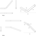
- the rectangular tube of the second elongate element is bended to form a first segment and a second segment wherein the first segment is at a fixed angle with respect to the second segment. It is an advantage of a rectangular tube that such tube is can withstand larger forces exerted thereon without bending over distance in comparison to for example a cylindrical tube. Therefore, a rectangular tube would be more rigid and resistant to displacement, and preserve better the original position when forces are exerted thereon by the first elongate element, connecting to the surgical instruments such as retractor devices.
- the medical fixation device is characterized in that, the second elongate element is a high-type second elongate element or a low-type second elongate element, depending on the fixed angle of the first segment with respect to the second segment. It is an advantage of providing different types of the second elongate element, that the medical fixation device is more adaptable to an individual surgery or patient.
- the medical fixation device is characterized in that the second elongate element comprises a first segment and a second segment, wherein the first segment is at a fixed angle with respect to the second segment.
- the second elongate element comprises a means for secure fixation of the first segment at a fixed angular position with respect to the second segment.
- the means for secure fixation of the second elongate element is configured to enable automatic secure fixation when the first segment reaches a selected fixed angular position relative to the second segment, for example by means of a mechanical force element such as a spring.
- the means for secure fixation of the second elongate element comprises a button, which is configured to enable switching between allowing rotatable connection of the first segment relative to the second segment, and securely fixing the first segment in at least one fixed angular position relative to the second segment.
- the fixed angle of the first segment with respect to the second segment in the second elongate element is adjustable between one or more fixed angular positions.
- the second elongate element comprises a bar and a second hinge, wherein the bar and a part of the second hinge form a first segment, and another part of the second hinge forms a second segment, and wherein the second hinge is configured to change the fixed angle between one or more fixed angular positions, causing that the first segment is at a fixed angular position with respect to the second segment.
- the second hinge of the second elongate element is configured to allow rotatable connection of the first segment relative to the second segment at an angular position selectable from 0° up to 360°.
- the second hinge of the second elongate element is configured to enable secure fixation of the first segment in more than one fixed angular position relative to the second segment at an angular position selectable from 0° up to 360°, such as every 30°, every 15°, every 10°, every 5° or every 1°.
- the second hinge of the second elongate element is configured to allow rotatable connection of the first segment relative to the second segment when the means for the secure fixation of the first segment at a fixed angular position with respect to the second segment is not connected, and to enable secure fixation of first segment in at least one fixed angular position relative to the second segment when the means for the secure fixation of the first segment at a fixed angular position with respect to the second segment is connected.
- the second hinge comprises a rotating hinge part and a base hinge part, wherein the rotating hinge part and the base hinge part are configured to allow rotatable connection of the rotating hinge part relative to the base hinge part when the means for the secure fixation of the first segment at a fixed angular position with respect to the second segment is not connected, and to enable secure fixation of the rotating hinge part in at least one fixed angular position relative to the base hinge part when the means for the secure fixation of the first segment at a fixed angular position with respect to the second segment is connected, and wherein the rotating hinge part and the base hinge part are configured for connecting the second hinge to respectively the base element and the bar of the second elongate element.
- the rotating hinge part comprises a hinge segment and a connection segment
- the base hinge part comprises a base hinge segment and a base connection segment
- the hinge segment and the base hinge segment are configured to allow rotatable connection of the rotating hinge part relative to the base hinge part when the means for the secure fixation of the first segment at a fixed angular position with respect to the second segment is not connected, and to enable secure fixation of the rotating hinge part in at least one fixed angular position relative to the base hinge part when the means for the secure fixation of the first segment at a fixed angular position with respect to the second segment is connected, and wherein the connection segment and the base connection segment are configured for connecting the second hinge to respectively the base element and the bar of the second elongate element.
- the means for secure fixation of the first segment at a fixed angular position with respect to the second segment of the second elongate element is part of the second hinge.
- the medical fixation device is characterized in that the base element comprises a cavity which is configured to receive a part of the second elongate element, and which is configured to receive the means for secure fixation of the part of the second elongate element in the cavity. It is an advantage that the cavity receives a part of the second elongate element, enclosing and securely fixing the second elongate element in the base element, which further minimizes displacement of the medical fixation device when forces are exerted thereon by the surgical instruments such as retractor devices.
- the medical fixation device is characterized in that the cavity of the base element is configured such that the part of the second elongate element can slide into the cavity from at least two different sides of the base element. It is an advantage that the second elongate element can be inserted into both ends of the base element, since this enables symmetric positioning of the medical fixation device on either side of the operating bed, and towards either the head or the feet of the patient.
- the medical fixation device is characterized in that the base element comprises a clamp which is configured for connecting the base element to the operating table and which is configured to receive the means for secure fixation of the clamp to the operating table. It is an advantage of using a clamp that it enables easy connection and secure fixation of the base element to the operating table, is compatible with different types of operating tables, and is a straight-forward, convenient and familiar design for the hospital personnel. A means for secure fixation of the clamp to the operating table in turn further stabilizes the medical fixation device when forces are exerted thereon by the surgical instruments.
- the medical fixation device is characterized in that the base element has a length of 80mm to 250mm, preferably 100mm to 200mm, more preferably 130mm to 170mm. It is an advantage of the chosen length that this provides sufficient support for robust and stable mounting of the medical fixation device on the operating table, while still being easy and convenient to move around, handle, connect and fix to the operating table.
- the medical fixation device is characterized in that the end of the first elongate element is directly connected to the end of the second elongate element. It is an advantage of such design that direct connection of the first elongate element to the second elongate element would enable simpler, more robust and more rigid connection, further minimizing displacement when forces are exerted on the medical fixation device by the surgical instruments.
- the medical fixation device is characterized in that the connection between the first elongate element and the connection part comprises a groove, preferably a groove with a shape corresponding to the shape of the outer surface of the first elongate element. It is an advantage of the described connection part that it makes the medical fixation device foldable, while at the same time preserving its robustness and resistance to displacement.
- the medical fixation device is characterized in that the groove of the connection part has a length of 50mm to 110mm, preferably 60mm to 100mm, more preferably 70mm to 90mm.
- the medical fixation device is characterized in that the connection between the first elongate element and the connection part comprises a safety pin for secure fixation of the first elongate element in at least one fixed angular position relative to the second elongate element. It is an advantage that a safety pin enables secure fixation of the first elongate element relative to the second elongate element, but when necessary can also easily be removed, such the first elongate element can be rotated with respect to the second elongate element into the folded configuration of the medical fixation device.
- the medical fixation device is characterized in that the connection part is configured to allow rotatable connection of the first elongate element relative to the second elongate element at an angular position selectable from 0° up to 360°.
- the connection part and the means for secure fixation of the first elongate element in at least one fixed angular position relative to the second elongate are configured to enable secure fixation of the first elongate element in more than one fixed angular position relative to the second elongate element at an angular position selectable from 0° up to 360°, such as every 30°, every 15°, every 10°, every 5° or every 1°.
- the means for secure fixation of the first elongate element in at least one fixed angular position relative to the second elongate comprises a button, which is configured to enable switching between allowing rotatable connection of the first elongate element relative to the second elongate element, and securely fixing the first elongate element in at least one fixed angular position relative to the second elongate element.
- the medical fixation device is characterized in that the connection part is a first hinge, wherein the first hinge comprises a rotating hinge part and a base hinge part, wherein the rotating hinge part and the base hinge part are configured to allow rotatable connection of the rotating hinge part relative to the base hinge part when the means for the secure fixation of the first elongate element in at least one fixed angular position relative to the second elongate element is not connected, and to enable secure fixation of the rotating hinge part in at least one fixed angular position relative to the base hinge part when the means for the secure fixation of the first elongate element in at least one fixed angular position relative to the second elongate element is connected, and wherein the rotating hinge part and the base hinge part are configured for connecting the first hinge to respectively the first elongate element and the second elongate element.
- the rotating hinge part comprises a hinge segment and a connection segment
- the base hinge part comprises a base hinge segment and a base connection segment
- the hinge segment and the base hinge segment are configured to allow rotatable connection of the rotating hinge part relative to the base hinge part when the means for the secure fixation of the first elongate element in at least one fixed angular position relative to the second elongate element) is not connected, and to enable secure fixation of the rotating hinge part in at least one fixed angular position relative to the base hinge part when the means for the secure fixation of the first elongate element in at least one fixed angular position relative to the second elongate element is connected, and wherein the connection segment and the base connection segment are configured for connecting the first hinge to respectively the first elongate element and the second elongate element.
- the means for secure fixation of the first elongate element in at least one fixed angular position relative to the second elongate element is part of the connection part.
- the medical fixation device is characterized in that the connection between the first elongate element and the connection part comprises a pin joint configured to allow rotatable connection of the first elongate element to the connection part. It is an advantage of a pin joint that a pin joint is a one degree of freedom joint only allowing rotation motion, which thus minimizes any other unwanted motion in the other directions and further stabilizes the connection.
- the medical fixation device comprises the first hinge and the second hinge, wherein preferably the first hinge and/or the second hinge, more preferably the first hinge and the second hinge, comprises a pin joint.
- the two hinges enable quick, convenient and effective installation of the medical fixation device, which is adapted to the individual patient and surgical situation.
- the medical fixation device is foldable. It is an advantage of the folded configuration that the medical fixation device can be easily transported and stored in assembled state, and at the same time very easily and quickly set up in the operating room.
- the medical fixation device is side-specific.
- the base element of the medical fixation device is side-specific. It is an advantage of the side-specific medical fixation device that the position of the device with respect to the patient is optimized. Furthermore, there is only one way the side-specific medical fixation device can be mounted onto the operation table, which eliminates the need for additional decision making during installation, and thus saves time and reduces the risk for mistakes.
- the medical fixation device is characterized in that the first elongate element, the extension element, the second elongate element, the base element and/or the connection part are made of a metal, such as aluminum and/or stainless steel, and/or a resilient composite material, such as polyoxymethylene. It is an advantage of these materials that they are very resilient and robust, and at the same time able to withstand conventional sterilization conditions.
- the medical fixation device is characterized in that the first elongate element, the second elongate element, the base element and the connection between the first elongate element and the second elongate element are configured such that, when fixed to the operating table and when forces of 90N, in particular horizontal or vertical transversal forces, are exerted on the first elongate element, the displacement of the first elongate element relative to the operating table is less than 10mm, preferably less than 7mm, more preferably less than 5mm. It is an advantage of a rigid medical fixation device that it will resist displacement when forces are exerted thereon, such that the final position of the surgical instrument is easy to assess and the movement of the device cannot distract the surgeon from the task at hand.
- the present invention concerns a medical device set comprising one or more medical fixation devices, preferably one or more medical fixation bars and one or more base elements, wherein a medical fixation bar is a medical fixation device without the base element.
- the medical device set comprises one high-type medical fixation bar, one low-type medical fixation bar and two base elements.
- the medical device set comprises two medical fixation devices such as two assembled medical fixation devices.
- the medical device set may comprise two side-specific medical fixation devices such as a left-sided medical fixation device and a right-sided medical fixation device.
- the present invention concerns a medical device system for keeping open a wound during surgery comprising one or more medical fixation devices.
- the medical device system further comprises one or more surgical instruments such as surgical retractors, one or more surgical drapes and/or one or more other medical devices for keeping open a wound during surgery.
- surgical instruments such as surgical retractors, one or more surgical drapes and/or one or more other medical devices for keeping open a wound during surgery.
- the present invention concerns a method for installation of the medical fixation device or the medical device set.
- the present invention relates to a method for installation of the medical device set, the method comprising the steps of:
- the method for installation of the medical device set comprising one high-type medical fixation bar, one low-type medical fixation bar and two base elements, comprises the method for installation of installation of the medical device set, wherein the high-type medical fixation device is installed in the up-orientation on the contralateral side of the surgical site, and the low-type medical fixation device is installed in the down-orientation on the ipsilateral side of the surgical site.
- the high-type medical fixation device is installed in the up-orientation on the contralateral side of the surgical site
- the low-type medical fixation device is installed in the down-orientation on the ipsilateral side of the surgical site.
- the present invention relates to a method for installation of the medical device set, the method comprising the steps of:
- the base hinge segment 1421 of the base hinge part 1420 comprises a base indentation 1423
- the hinge segment 1411 of the rotating hinge part 1410 comprises one or more rotating part indentations 1413
- the base indentation 1423 and the rotating part indentations 1413 are configured to receive a part of the hinge fixation means 1460 and wherein the simultaneous receiving of part of the hinge fixation means 1460 by the base indentation 1423 of the base hinge part 1420 and one of the rotating part indentations 1413 of the rotating hinge part 1410 results in the secure fixation of the rotating hinge part 1410 relative to the base hinge part 1420 in a fixed angular position.
- the rotating hinge part 1410 comprises three rotating part indentations 1413.
- the three indentations 1413 enable secure fixation of the rotating hinge part 1410 in three fixed angular positions with respect to the base hinge part 1420: a high angular position 1491, a low angular position 1492 and a folded angular position 1490.
- the high angular position 1491 is a fixed angular position of 100° to 160°, preferably 110° to 150°, more preferably 120° to 140°.
- the low angular position 1492 is a fixed angular position of 200° to 260°, preferably 210° to 250°, more preferably 220° to 240°.
- the rotating hinge part 1410 comprises more than one rotating part indentations 1413 at equal distances from each other, such as every 30°, every 15°, every 10°, every 5° or every 1°. This enables a greater adaptability of the fixed angular position to a unique subject and surgery.
- the hinge fixation means 1460 is configured to perform an axial translation movement relative to the indentations 1413, 1423.
- This can be realized by any means to obtain one-dimensional translational movement known in the art.
- the axial translation movement of the hinge fixation means 1460 relative to the indentations 1413, 1423 is a one-dimensional axial translation movement.
- the axial translational movement of the hinge fixation means 1460 away from the indentations 1413, 1423 enables rotational movement of the rotating hinge part 1410 with respect to the base hinge part 1420.
- the axial translational movement of the hinge fixation means 1460 towards and into the indentations 1413, 1423 results in the secure fixation of the rotating hinge part 1410 in an angular position with respect to the base hinge part 1420.
- the fixation mechanism in particular the means 1450 for secure fixation, is configured to enable automatic secure fixation of the rotating hinge part 1410 in an angular position with respect to the base hinge part 1420, when the base indentation 1423 is aligned with one of the rotating part indentations 1413.
- the fixation mechanism in particular the means 1450 for secure fixation, comprises a force element 1451 which creates a force on the hinge fixation means 1460 in the axial translation direction towards the indentations 1413, 1423 causing the automatic axial translation movement of the hinge fixation means 1460 into the indentations 1413, 1423.
- the force element 1451 is a mechanical force element, more preferably a spring.
- the axial translation movement of the hinge fixation means 1460 is realized by providing a button cover 1461 on one side of the hinge fixation means 1460 and a button base 1462 on the other side of the hinge fixation means 1460.
- the button cover 1461, the button base 1462 and the hinge fixation means 1460 are configured such that when assembled, the hinge fixation means 1460 can only move in one axial translation direction between the button cover 1461 and the button base 1462.
- the button cover 1461 and/or the button base 1462 comprise one or more guiding rails 1463, which are configured to prevent sideways movement of the hinge fixation means 1460.
- the button cover 1461 and/or the button base 1462 comprise one or more spring guides 1464, which are configured to guide the force element 1451, in particular the spring, when compressed and de-compressed in the axial translation direction.
- the spring guides 1464 may also be configured to create the end position of the hinge fixation means 1460 when moved away from the indentations 1413, 1423.
- the button base 1462 is assembled to the base hinge segment 1421 of the base hinge part 1420 through one or more openings 1468.
- the first hinge 1400 comprises one or more fixation means 1467 to assemble the button base 1462 through the one or more openings 1468 in the button base 1462 and one or more corresponding openings 1427 in the base hinge segment 1421.
- the hinge fixation means 1460 and force element 1451 in particular the spring, can be positioned in the button base 1462, and the button cover 1461 can be assembled over the hinge fixation means 1460.
- the button cover 1461 is assembled with one or more fixation means 1465 to the base hinge segment 1421 through the one or more openings 1466 in the button cover 1461 and one or more corresponding openings 1426 in the base hinge segment 1421.
- the button base 1462 and the button cover 1461 may be assembled to the hinge segment 1411 of the rotating hinge part 1410.
- the fixation means 1465 and 1467 is a screw.
- the hinge segment 1411 of the rotating hinge part 1410 is configured to assemble a slider 1470, which is configured to smoothly guide the rotation movement of the rotating hinge part 1410 with respect to the button cover 1461.
- the slider 1470 comprises one or more openings 1472 to be assembled with fixation means 1471.
- the fixation means 1471 securely fixes the slider 1470 to the hinge segment 1411 of the rotating hinge part 1410 through one or more openings 1472 in the slider 1470, and one or more corresponding openings 1417 in the hinge segment 1411.
- the means 1450 for secure fixation comprises the hinge fixation means 1460, the button cover 1461 and the button base 1462.
- the hinge fixation means 1460 comprises the button 1452, the opening 1453 and the dent 1454.
- the base hinge segment 1421 of the base hinge part 1420 comprises the hinge fixation means 1460, the button cover 1461 and the button base 1462.
- connection segment 1412 of the rotating hinge part 1410 and the base connection segment 1422 of the base hinge part 1420 are configured to be connected to and securely fixed to either the first elongate element 1100 or the second elongate element 1200.
- connection segment 1412 of the rotating hinge part 1410 is configured to be connected to and securely fixed to the second elongate element 1200
- base connection segment 1422 of the base hinge part 1420 is configured to be connected to and securely fixed to the first elongate element 1100.
- connection segment 1412 of the rotating hinge part 1410 is configured to be connected to and securely fixed to the first elongate element 1100
- base connection segment 1422 of the base hinge part 1420 is configured to be connected to and securely fixed to the second elongate element 1200.
- connection segment 1412 comprises a tube 1416 and the base connection segment 1422 comprises a tube 1428.
- Each of the tubes 1416, 1428 may be a cylindrical tube or a polygonal tube, preferably a cylindrical tube or a rectangular tube, more preferably a cylindrical tube.
- each of the tubes 1416, 1428 is a solid tube.
- one or both of the tubes 1416, 1428 is a hollow tube.
- connection segment 1412 or 1422 in particular the tube 1416 or 1428, which connects to the first elongate element 1100 comprises a means 1415 for secure fixation of the connection segment to the first elongate element 1100.
- means for secure fixation are well-known to a skilled person, and may comprise, but are not limited to, one or more screws, one or more bolts, glue, one or more clamps, one or more pipe couplings, or combinations of those.
- the means 1415 for secure fixation of the first hinge 1400 to the first elongate element 1100 comprises a female threaded hole 1415, which is configured to accommodate the male thread 1105 of the first elongate element 1100.
- the female threaded hole 1415 is illustrated in FIGs. 16 and 18 ; the male thread 1105 is illustrated in FIG. 15 .
- connection segment 1412 or 1422 in particular the tube 1416 or 1428, which connects to the second elongate element 1200 comprises one or more openings 1429, which are configured to accommodate the means 1207, in particular the screws, for secure fixation of the second elongate element 1200 to the first hinge 1400.
- the connection segment 1412 or 1422 comprises two or more openings 1429. More preferably, the connection segment 1412 or 1422, comprises two openings 1429, wherein the distance between the two openings 1429 is 20mm to 60mm, preferably 30mm to 50mm, more preferably 35mm to 45mm.
- the connection segment 1412 of the rotating hinge part 1410 comprises the one or more openings 1429.
- FIGs. 19-22 embodiments of standard and optional components of the second elongate element 1200, are depicted in FIGs. 19-22 .
- the second elongate element 1200 comprises a bar 1600 and a second hinge 1700.
- the second hinge 1700 comprises a base hinge part 1720 and a rotating hinge part 1710.
- the second hinge 1700 connects to the bar 1600 of the second elongate element 1200 and to the base element 1300, as shown in FIG. 14 .
- the second elongate element 1200 comprises a first segment 1202 and a second segment 1203, wherein the first segment 1202 can be fixed at a fixed angle with respect to the second segment 1203.
- the first segment 1202 is further configured to be connected to the first hinge 1400.
- the second segment 1203 is configured to be connected to the base element 1300.
- the fixed angle of the first segment 1202 with respect to the second segment 1203 is adjustable between fixed angular positions.
- the second elongate element 1200 is configured to enable changing the fixed angle of the first segment 1202 with respect to the second segment 1203 between fixed angular positions. This can be realized by any means to position two segments at a fixed angle known in the art.
- the second hinge 1700 is configured to enable changing the fixed angle causing that the first segment 1202 is at a fixed angle with respect to the second segment 1203 between fixed angular positions. As shown in FIGs. 14 and 19 , typically the bar 1600 and a part of the second hinge 1700 form the first segment 1202 of the second elongate element 1200, and another part of the second hinge 1700 forms the second segment 1203 of the second elongate element 1200.
- the bar 1600 and one of the hinge parts, the base hinge part 1720 or the rotating hinge part 1710 form a first segment 1202 of the second elongate element 1200 and the other hinge part, the rotating hinge part 1710 or the base hinge part 1720 respectively, forms a second segment 1203, wherein the first segment 1202 is at a fixed angle with respect to the second segment 1203.
- the second elongate element 1200 is configured to enable changing the fixed angle of the first segment 1202 with respect to the second segment 1203 between two or more fixed angular positions.
- the second hinge 1700 is configured to enable changing the fixed angle of the first segment 1202 with respect to the second segment 1203 between two or more fixed angular positions.
- the base hinge part 1720 connects to the base element 1300 and the rotating hinge part 1710 connects to the bar 1600.
- the rotating hinge part 1710 and the bar 1600 form the first segment 1202 of the second elongate element 1200 and the base hinge part 1720 forms the second segment 1203, wherein the first segment 1202 is at a fixed angle with respect to the second segment 1203.
- the base hinge part 1720 connects to the bar 1600 and the rotating hinge part 1710 connects to the base element 1300.
- the base hinge part 1720 and the bar 1600 form the first segment 1202 of the second elongate element 1200 and the rotating hinge part 1710 forms the second segment 1203, wherein the first segment 1202 is at a fixed angle with respect to the second segment 1203.
- the bar 1600 is typically a cylindrical bar or a rectangular bar, preferably a cylindrical bar.
- the second elongate element would comprise a hollow cylindrical bar.
- a hollow aspect of the second elongate element helps reducing the weight of the medical fixation device, facilitating its setup and manipulation during surgery.
- the second elongate element 1200 comprises a solid cylindrical or rectangular bar.
- the bar 1600 of the second elongate element 1200 would typically have a length of 300mm to 600mm, preferably 500mm to 600mm, more preferably 525mm to 575mm.
- a rectangular bar would typically have a width of 20mm to 60mm, preferably 30mm to 50mm, more preferably 30mm to 40mm.
- a cylindrical bar would typically have a diameter of 20mm to 60mm, preferably 30mm to 50mm, more preferably 30mm to 40mm. These dimensions of the bar 1600 of the second elongate element 1200 allow for substantial coverage of the space around the operating table, while at the same time maintaining the robustness and resilience of the second elongate element when forces are exerted thereon by the first elongate element.
- the bar of the second elongate element 1200 is a circular bar.
- the bar 1600 of the second elongate element 1200 is configured to be connected to the first hinge 1400 and to the second hinge 1700.
- the bar 1600 comprises a first cavity 1604 at the first end 1602, which is configured to receive a part of the first hinge 1400, in particular the tube 1428 of the first hinge 1400, and a second cavity 1605 at the second end 1603, which is configured to receive a part of the second hinge 1700.
- the first cavity 1604 and the second cavity 1605 of the bar 1600 is a cylindric cavity.
- the first cavity 1604 and/or the second cavity 1605 of the bar 1600 is a polygonal cavity.
- polygonal cavities are well-known to those skilled in the art, and comprise, but are not limited to, a triangular cavity, a rectangular cavity, a pentagonal cavity, a hexagonal cavity, a heptagonal cavity, an octagonal cavity, a dodecagonal cavity.
- the first cavity 1604 and/or the second cavity 1605 of the second elongate element 1200 is a rectangular cavity.
- the second elongate element 1200 comprises a means 1607 for secure fixation of the first hinge1400 and the second hinge 1700 to the bar 1600, as shown in FIG. 14 .
- the means 1607 for secure fixation may comprise, but is not limited to, one or more screws, one or more bolts, glue, one or more clamps, or one or more pipe couplings.
- the bar 1600 comprises one or more openings 1606 at the first end 1602 and at the second end 1603, wherein the openings 1606 are configured to accommodate the means 1607 for secure fixation.
- the bar 1600 comprises two or more openings 1606 at each end 1602, 1603.
- the openings 1606 and the means 1608 for secure fixation are identical on both ends 1602, 1603 of the bar 1600.
- the openings 1606 at the first end 1602 of the second elongate element 1200 are aligned with the corresponding openings 1429 of the first hinge 1400, which are configured to accommodate the means 1607, in particular the screws, for secure fixation of the second elongate element 1200 to the first hinge 1400.
- the means 1607 for secure fixation may be part of the bar 1600.
- the bar 1600 comprises two openings 1606 at each end 1602, 1603 of the bar 1600.
- the openings 1606 are aligned in line with the axis of the bar 1600 and are identical on both ends 1602, 1603 of the bar 1600.
- the distance between the two openings 1606 at each end 1602, 1603 of the bar 1600 is 20mm to 60mm, preferably 30mm to 50mm, more preferably 35mm to 45mm.
- the two openings 1606 are at a distance of 10mm to 30mm, preferably 15mm to 25mm, more preferably 18mm to 22mm from each end 1602, 1603 of the bar 1600.
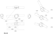
- the second hinge 1700 comprises a base hinge part 1720 and a rotating hinge part 1710.
- the second hinge 1700 connects to the bar 1600 of the second elongate element 1200 and to the base element 1300.
- the base hinge part 1720 connects to the base element 1300 and the rotating hinge part 1710 connects to the bar 1600.
- the base hinge part 1720 connects to the bar 1600 and the rotating hinge part 1710 connects to the base element 1300.
- the means 1750 for secure fixation is releasable by a fixation mechanism which is configured to allow rotation of the rotation hinge part 1710 relative to the base hinge part when the means 1750 for secure fixation is in an inactive position and to lock the rotation hinge part 1710 relative to the base hinge part when the means 1750 for secure fixation is in an active position.
- the means 1750 for secure fixation is configured to enable secure fixation of the rotating hinge part 1710 with respect to the base hinge part 1720 in at least one fixed angular position of the rotating hinge part 1710 with respect to the base hinge part 1720.
- the means 1750 for secure fixation is located in the hinge space 1730.
- the part of hinge fixation means 1760 which is receivable in the indentations is a dent 1754.
- the hinge fixation means 1760 comprises the dent 1754.
- the base indentation 1713 and the rotating part indentations 1723 are located inside the hinge space 1730.
- the base and the rotating part indentations 1713, 1723 are U-shaped indentations, as illustrated in FIGs. 21-22 , and the part of the hinge fixations means 1760 which is receivable in the indentations 1713, 1723, in particular the dent 1754, has a shape corresponding to the shape of the indentations.
- the dent 1754 is also a U-shaped dent 1754, as illustrated in FIG. 22 .
- the hinge fixation means 1760 is configured to perform an axial translation movement relative to the indentations 1713, 1723.
- This can be realized by any means to obtain one-dimensional translational movement known in the art.
- the axial translation movement of the hinge fixation means 1760 relative to the indentations 1713, 1723 is a one-dimensional axial translation movement.
- the axial translational movement of the hinge fixation means 1760 away from the indentations 1713, 1723 enables rotational movement of the rotating hinge part 1710 with respect to the base hinge part 1720.
- the axial translational movement of the hinge fixation means 1760 towards and into the indentations 1713, 1723 results in the secure fixation of the rotating hinge part 1710 in an angular position with respect to the base hinge part 1720.
- the fixation mechanism in particular the means 1750 for secure fixation, is configured to enable automatic secure fixation of the rotating hinge part 1710 in an angular position with respect to the base hinge part 1720, when the base indentation 1723 is aligned with one of the rotating part indentations 1713.
- the fixation mechanism in particular the means 1750 for secure fixation, comprises a force element 1751 which creates a force on the hinge fixation means 1760 in the axial translation direction towards the indentations 1713, 1723 causing the automatic axial translation movement of the hinge fixation means 1760 into the indentations 1713, 1723.
- the force element 1751 is a mechanical force element, more preferably a spring.
- the fixation mechanism in particular the means 1750 for secure fixation comprises a button 1752, which is configured to enable switching between allowing rotatable connection of the first segment 1202 relative to the second segment 1203 of the second elongate element 1200, and securely fixing the first segment 1202 in at least one fixed angular position relative to the second segment 1203.
- the second hinge 1700 comprises a button 1752, which is configured to enable switching between allowing the rotation of the rotating hinge part 1710 relative to the base hinge part 1720, and the secure fixation of the rotating hinge part 1710 relative to the base hinge part 1720 in at least one fixed angular position.
- This button 1752 enables easy and intuitive manipulation by the surgeon to quickly switch between rotational movement and secure fixation of the connection between the first segment 1202 and the second segment 1203, in particular the second hinge 1700 and thus to optimally position the medical fixation device for surgery with minimal effort.
- the hinge segment 1711 of the rotating hinge part 1710 and/or the base hinge segment 1721 of the base hinge part 1720 comprises a button opening 1725, which is configured to accommodate the button 1752 and to allow a user to press the button.
- the button 1752 is part of the hinge fixation means 1760 and is configured such that moving the button 1752 inwards causes the hinge fixation means 1760 to move in the axial translation direction out of the indentations 1713, 1723.
- the axial translation movement of the hinge fixation means 1760 is realized by providing a button cover 1761 on one side of the hinge fixation means and a button base 1762 on the other side of the hinge fixation means 1760.
- the button cover 1761, the button base 1762 and the hinge fixation means 1750 are configured such that when assembled, the hinge fixation means 1760 can only move in one axial translation direction between the button cover 1761 and the button base 1762.
- the button cover 1761 and/or the button base 1762 comprise one or more guiding rails 1763, which are configured to prevent sideways movement of the hinge fixation means 1760.
- the button cover 1761 and/or the button base 1762 comprise one or more spring guides 1764, which are configured to guide the force element 1751, in particular the spring, when compressed and de-compressed in the axial translation direction.
- the spring guides 1764 may also be configured to create the end position of the hinge fixation means 1760 when moved away from the indentations 1713, 1723.
- the button base 1762 is assembled to the base hinge segment 1721 of the base hinge part 1720 through one or more openings 1768.
- the second hinge 1700 comprises one or more fixation means 1767 to assemble the button base 1762 through the one or more openings 1768 in the button base 1762 and one or more corresponding openings 1727 in the base hinge segment 1721.
- the hinge fixation means 1760 and force element 1751 in particular the spring, can be positioned in the button base 1762, and the button cover 1761 can be assembled over the hinge fixation means 1760.
- the button cover 1761 is assembled with one or more fixation means 1765 to the base hinge segment 1721 through the one or more openings 1766 in the button cover 1761 and one or more corresponding openings 1726 in the base hinge segment 1721.
- the button base 1762 and the button cover 1761 may be assembled to the hinge segment 1711 of the rotating hinge part 1710.
- the fixation means 1765 and 1767 is a screw.
- the hinge segment 1711 of the rotating hinge part 1710 is configured to assemble a slider 1770, which is configured to smoothly guide the rotation movement of the rotating hinge part 1710 with respect to the button cover 1761.
- the slider 1770 comprises one or more openings 1772 to be assembled with fixation means 1771.
- the fixation means 1771 securely fixes the slider 1770 to the hinge segment 1711 of the rotating hinge part 1710 through one or more openings 1772 in the slider 1770, and one or more corresponding openings 1717 in the hinge segment 1711.
- the means 1750 for secure fixation comprises the hinge fixation means 1760, the button cover 1761 and the button base 1762.
- the hinge fixation means 1760 comprises the button 1752, the opening 1753 and the dent 1754.
- the base hinge segment 1721 of the base hinge part 1720 comprises the hinge fixation means 1760, the button cover 1761 and the button base 1762.
- connection segment 1712 of the rotating hinge part 1710 and the base connection segment 1722 of the base hinge part 1720 are configured to be connected to and securely fixed to either the bar 1600 of the second elongate element 1200 or the base element 1300.
- connection segment 1712 of the rotating hinge part 1710 is configured to be connected to and securely fixed to the bar 1600 of the second elongate element 1200
- base connection segment 1722 of the base hinge part 1720 is configured to be connected to and securely fixed to the base element 1300.
- connection segment 1712 of the rotating hinge part 1710 is configured to be connected to and securely fixed to the base element 1300
- base connection segment 1722 of the base hinge part 1720 is configured to be connected to and securely fixed to the bar 1600 of the second elongate element 1200.
- connection segment 1712 comprises a tube 1718 and the base connection segment 1722 comprises a tube 1728.
- Each of the tubes 1718, 1728 may be a cylindrical tube or a polygonal tube, preferably a cylindrical tube or a rectangular tube, more preferably a cylindrical tube.
- each of the tubes 1718, 1728 is a solid tube.
- one or both of the tubes 1718, 1728 is a hollow tube.
- connection segment 1712 in particular the tube 1718
- connection segment 1722 in particular the tube 1728
- the openings 1719, 1729 are configured to accommodate either the means 1607 for secure fixation to the bar 1600 of the second elongate element 1200, or the means 1305 for secure fixation to the base element 1300.
- the base element 1300 is configured to be connected to the operating table 502 and comprises a means 1303 for secure fixation of the base element to the operating table.
- the base element 1300 would typically have a length of 80mm to 250mm, preferably 100mm to 200mm, more preferably 100mm to 130mm.
- the base element would typically have a width of 60mm to 100mm, preferably 70mm to 90mm, more preferably 75mm to 85mm.
- the base element 1300 would typically have a height of 40mm to 80mm, preferably 50mm to 70mm, more preferably 55mm to 65mm.
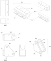
- the base element 1300 comprises one or more clamps 1301, which are configured to be connected and securely fixated to the operating table 502.
- the base element 1300 comprises one clamp 1301, as shown in FIG. 25 .
- the one clamp 1301 can be a left-sided clamp or a right-sided clamp 1301, resulting in a left-sided or a right-sided medical fixation device 1001 respectively.
- This side-specific design of the base element 1300 and the corresponding medical fixation device 1001 enables positioning of the medical fixation device further away from the edge of the operating table, which provides more space on the operating table.
- the base element 1300 comprises two clamps 1301, in particular one clamp 1301 on each of the two opposite long sides 1320 of the base element, as shown in FIGs. 23-24 .
- the presence of a clamp on each long side 1320 of the base element 1300 facilitates convenient use of the medical fixation device 1001 on both sides of the operating table 502.
- the one or more clamps 1300 comprise a means 1303 for secure fixation of the clamps to the operating table.
- the one or more clamps 1301 are configured to be releasably connected to the operating table 502, in particular to the rail of the operating table.
- the one or more clamps 1301 comprise one or more screws 1303, preferably one or two screws, in one or more corresponding openings 1304 for secure fixation of the clamp to the operating table, as illustrated in FIG. 23 .
- the openings 1304 are located at the bottom 1350 of the base element 1300.
- the various types of screws suitable for secure fixation of the clamp to the operating table are known to those skilled in the art, and comprise but are not limited to, wing screws, shelf screws, bolts etc.
- the base element 1300 comprises two clamps 1301, in particular one clamp 1301 on each of the two opposite long sides 1320 of the base element.
- the two clamps 1301 are identical.
- each clamp 1301 comprises two means 1303 for secure fixation of the clamp to the operating table.
- the means for secure fixation 1303 comprises screws.
- each of the clamps comprises two openings 1304, which are configured to accommodate the means 1303 for secure fixation.
- the distance between the two openings 1304 in each clamp is 40mm to 80mm, preferably 50mm to 70mm, more preferably 55mm to 65mm.
- the two short sides of the base element are also referred to as the first end 1331 and the second end 1332
- the base element 1300 is configured to be connected to the second elongate element 1200, in particular the second segment 1203 of the second elongate element 1200, more in particular one of the connection segments 1712, 1722 of the second hinge 1700.
- the base element 1300 comprises a cavity 1302, which is configured to receive a part of the second elongate element 1200, in particular a part of the second segment 1203 of the second elongate element 1200, more in particular one of the connection segments 1712, 1722 of the second hinge 1700.
- the said cavity 1302 is located at the first end 1331 of the base element 1300.
- the cavity 1302 of the base element 1300 is a cylindric cavity.
- the cavity 1302 of the base element 1300 is a polygonal cavity. Examples of polygonal cavities are analogous to those described for the cavities 1604, 1605 of the bar 1600 of the second elongate element 1200. In another preferred embodiment, the cavity 1302 of the base element 1300 is a rectangular cavity.
- the base element 1300 comprises a means 1305 for secure fixation of the second elongate element 1200 to the base element 1300.
- the fixation means 1305 is analogous to the means 1607 of the bar 1600 of the second elongate element 1200.
- the base element 1300 comprises one or more openings 1306 wherein the openings 1306 are configured to accommodate the means 1305 for secure fixation of the second connection part 1700 to the base element 1300.
- the base element 1300 comprises two or more openings 1306 on top 1340 of the base element.
- the openings 1306 are aligned in line with the long axis of the base element 1300.
- the base element 1300 comprises two openings 1306 at the top 1340 of the base element, wherein the openings 1306 are aligned in line with the long axis of the base element 1300.
- the distance between the two openings 1306 of the base element 1300 is 30mm to 70mm, preferably 40mm to 60mm, more preferably 45mm to 55mm.
- FIGs. 26-29 the standard and optional components of the second alternative embodiment of the medical fixation device 2001 are depicted in FIGs. 26-29 .
- the medical device 2001 is largely analogous to the medical fixation device 1001.
- the medical fixation device 2001 is completely assembled, as illustrated in FIGs. 26 and 29 .
- the medical fixation device 2001 is side-specific: in FIG. 26 , the right-sided medical fixation device (on the left) is mounted on the right-hand side of the operating table 502 and the left-sided medical fixation device (on the right) is mounted on the left-hand side of the operating table 502.
- the base element 2300 is side-specific. It is an advantage of the side-specific medical fixation device 2001 that the position of the device with respect to the patient is optimized. Furthermore, there is only one way the side-specific medical fixation device 2001 can be mounted onto the operation table 502, which eliminates the need for additional decision making during installation, and thus saves time and reduces the risk for mistakes.
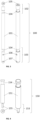
- the first elongate element 2100 comprises a tube 2101, preferably a cylindrical tube 2101.
- the first elongate element 2100, in particular the tube 2101 comprises a first end 2102 and a second end 2103.
- the tube 2101 is a solid cylindrical tube. It is an advantage of the solid tube that it has a lower manufacturing cost.
- the tube 2101 may be hollow.
- the first elongate element 2100 corresponds to an extended first elongated element 160, wherein the extension element 150 is coupled onto the first elongate element 100.
- the extension element 150 is permanently fixed and integrated with the first elongate element 100. Therefore, the length of the first elongate element 2100 corresponds to the sum of the length of the first elongate element 100 and the extension element 150.
- the first elongate element 2100 would typically have a length of 450mm to 850mm, preferably 550mm to 750mm, more preferably 590mm to 670mm. Most preferably, the first elongate element 2100 has a length of 650mm to 670mm.
- the cylindrical tube would typically have a diameter of 15mm to 35mm, preferably 20mm to 30mm, more preferably 23mm to 27mm.
- the first elongate element 2100 comprises two or more, preferably three or more connection members 2104, each of which is configured to be releasably connected to one or more surgical instruments 600, such as one or more surgical retractors 500.
- the connection members 1104 are indentations.
- an indentation 1104 would typically have a length of 10mm to 30mm, preferably 20mm to 30mm, more preferably 23mm to 27mm, and would typically have a depth of 2.0mm to 5.0mm, preferably 3.0mm to 4.0mm, more preferably 3.2mm to 3.5mm.
- the indentations 1104 are circumferential indentations, preferably cylindrical circumferential indentations.
- the first elongate element 2100 is securely fixed in at least one fixed angular position relative the second elongate element 2200 by means of a means 2450 for secure fixation.
- the first elongate element 2100 is configured to be connected to and securely fixed to the connection part 2400.
- the first elongate element 2100 is rotatably connected to the second elongate element 2200 by means of a connection part 2400.
- the connection part 2400 is also referred to as the first hinge 2400.
- the means 2450 for secure fixation is releasable by a fixation mechanism which is configured to allow rotation of the first elongate element 2100 relative to the second elongate element 2200 when the means 2450 for secure fixation is in an inactive position and to lock the first elongate element 2100 relative to the second elongate element 2200 when the means 2450 for secure fixation is in an active position.
- the first hinge 2400 and the means 2450 for secure fixation of the first elongate element 2100 in at least one fixed angular position relative to the second elongate element 2200 are configured to enable secure fixation of the first elongate element 2100 in more than one fixed angular position relative to the second elongate element 2200 at an angular position selectable from 0° up to 360°, such as every 30°, every 15°, every 10°, every 5° or every 1°.
- the fixation mechanism in particular the means 2450 for secure fixation, is configured to enable automatic secure fixation of the first elongate element 2100 in at least one fixed angular position relative to the second elongate element 2200, when the first elongate element 2100 reaches a selected fixed angular position relative to the second elongate element 2200, for example by means of a mechanical force element such as a spring.
- the first hinge 2400 is configured to be connected to and securely fixed to the first elongate element 2100 and to the second elongate element 2200.
- the second elongate element 2200 comprises a bar 2600 and a second hinge 2700.
- the second hinge 2700 connects to the bar 2600 of the second elongate element 2200 and to the base element 2300.
- the second elongate element 2200 comprises a first segment 2202 and a second segment 2203, wherein the first segment 2202 can be fixed at a fixed angle with respect to the second segment 2203 (shown in FIG. 27 ).
- the first segment 2202 of the second elongate element 2200 is further configured to be connected to the first hinge 2400.
- the second segment 2203 of the second elongate element 2200 is configured to be connected to the base element 2300.
- the second elongate element 2200 is configured to enable changing the fixed angle of the first segment 2202 with respect to the second segment 2203 between fixed angular positions.
- the second hinge 2700 is configured to enable changing the fixed angle causing that the first segment 2202 is at a fixed angle with respect to the second segment 2203 between fixed angular positions.
- the bar 2600 and a part of the second hinge 2700 form the first segment 2202 of the second elongate element 1200, and another part of the second hinge 2700 forms the second segment 2203 of the second elongate element 1200.
- the bar 2600 is a cylindrical bar. More preferably, the bar 2600 is a solid cylindrical bar.
- the bar 2600 of the second elongate element 1200 would typically have a length of 500mm to 900mm, preferably 600mm to 800mm, more preferably 650mm to 750mm.
- the cylindrical bar would typically have a diameter of 20mm to 60mm, preferably 30mm to 50mm, more preferably 30mm to 40mm.
- the bar 2600 of the second elongate element 2200 is configured to be connected to the first hinge 2400 and to the second hinge 2700.
- the second hinge 2700 connects to the bar 2600 of the second elongate element 2200 and to the base element 2300.
- the second hinge 2700 is configured such that the first segment 2202 of the second elongate element 2200 can rotatably connect relative to the second segment 2203 of the second elongate element 2200 at an angle selectable from 0° up to 360°.
- the second hinge 2700 comprises a pin joint. The selected angle somewhere between 0° and 360° is fixed by a means 2750 to keep the selected angle in the selected position.
- the means 2750 for secure fixation is releasable by a fixation mechanism which is configured to allow rotation of the first segment 2202 of the second elongate element 2200 relative to the second segment 2203 of the second elongate element 2200 when the means 2750 for secure fixation is in an inactive position and to lock the first segment 2202 of the second elongate element 2200 relative to the second segment 2203 of the second elongate element 2200 when the means 2750 for secure fixation is in an active position.
- the second hinge 2700 and the means 2750 for secure fixation of the first segment 2202 of the second elongate element 2200 in at least one fixed angular position relative to the second segment 2203 of the second elongate element 2200 are configured to enable secure fixation of the first segment 2202 of the second elongate element 2200 in more than one fixed angular position relative to the second segment 2203 of the second elongate element 2200 at an angular position selectable from 0° up to 360°, such as every 30°, every 15°, every 10°, every 5° or every 1°.
- the fixation mechanism in particular the means 2750 for secure fixation, is configured to enable automatic secure fixation of the first segment 2202 of the second elongate element 2200 relative to the second segment 2203 of the second elongate element 2200, when the first segment 2202 of the second elongate element 2200 reaches a selected fixed angular position relative to the second segment 2203 of the second elongate element 2200, for example by means of a mechanical force element such as a spring.
- the fixation mechanism in particular the means 2750 for secure fixation comprises a button, which is configured to enable switching between allowing rotatable connection of the first segment 2202 of the second elongate element 2200 relative to the second segment 2203 of the second elongate element 2200, and securely fixing the first segment 2202 of the second elongate element 2200 in at least one fixed angular position relative to the second segment 2203 of the second elongate element 2200.
- the base element 2300 is configured to be connected to the operating table 502 and comprises a means 2303 for secure fixation of the base element to the operating table.
- the base element 2300 would typically have a length of 80mm to 250mm, preferably 80mm to 130mm, more preferably 80mm to 90mm.
- the base element 2300 would typically have a width of 40mm to 70mm, preferably 50mm to 60mm.
- the base element 2300 with smaller dimensions is more convenient to use: it makes the medical fixation device 2001 lighter, such that it is easier to handle and to install in the operating room; it also requires less space to attach the medical fixation device 2001 to the operating table 502, in particular to the rail of the operating table, along with other medical devices which need to be fixed to the operating table for surgery. Meanwhile, the described dimensions of the base element 2300 still enable stable attachment of the medical fixation device 2001 to the operating table 502.
- the base element 2300 comprises one or more clamps 2301, which are configured to be connected and securely fixed to the operating table 502.
- the base element 2300 comprises one clamp 2301.
- the clamp 2301 is side-specific.
- FIG. 26 illustrates a left-sided clamp (on the right side of the Fig 26 ) and a right-sided clamp (on the left side of the Fig 26 ), resulting in a left-sided or a right-sided medical fixation device 2001 respectively.
- each clamp 2301 comprises one or more means 2303 for secure fixation of the clamp to the operating table.
- the base element 2300 is configured to be connected to the second elongate element 2200, in particular the second segment of the second elongate element 1200, more in particular the second hinge 2700.
- the base element 2300 comprises a cavity 2302, which is configured to receive a part of the second elongate element 2200, in particular a part of the second segment 2203 of the second elongate element 2200, more in particular a part of the second hinge 2700.
- An example of such cavity 2302 is illustrated in FIG. 28 .
- the cavity 2302 of the base element 2300 is a cylindric cavity.
- the described elements (the first elongate element 100, 1100, 2100, the extension element 150, the second elongate element 200, 1200, 2200, the base element 300, 1300, 2100, the connection part 400, 1400, 2400, the second hinge 1700, 2700) would need to be manufactured from rigid and resilient material, such that these elements remain intact and preserve their position under the forces exerted on the medical fixation device by the surgical instruments.
- the materials of the medical fixation device should be able to withstand conventional cleaning conditions.
- the described elements are made of a metal.
- the metal may comprise, but is not limited to carbon steel, stainless steel, aluminum, titanium, or any other metal which is suitable for manufacturing of medical devices for use in surgery.
- the described elements are made of aluminum and/or stainless steel.
- the described elements may also be made from a resilient composite material, such as a carbon fiber composite, or from a rigid thermoplastic material such as polyoxymethylene or polyaryletherketone.
- the described elements are made of aluminum, stainless steel and/or polyoxymethylene. Different elements may be made of different materials.
- other materials may also be used for the manufacture of the medical fixation device, such as plastic, rubber, silicone, other metals, resins, polymers, and other materials which are suitable for the manufacture of medical devices.
- the rotatable connection of the first elongate element 100, 1100, 2100 with respect to the second elongate element 200, 1200, 2200 enables convenient folding and unfolding of the medical fixation device 001, 1001, 2001.
- the foldable design facilitates transportation and storage of the device, while simultaneously enabling easy assembly.
- the structure of the foldable design realized by the specific structure of the connection between the first elongate element 100, 1100, 2100 and the second elongate element 200, 1200, 2200, in particular connection part 400, 1400, 2400 provides a foldable structure which provides, after secure fixation in the predefined angle, a very robust medical fixation device that preserves its position under the forces exerted on the medical fixation device by surgical instruments.
- the second hinge 1700, 2700 of the second elongate element 1200, 2200 enables an even more compact folded configuration.
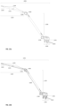
- FIG. 24 illustrates two examples of the unfolded configurations (on the left) and the folded configuration (on the right) of the medical fixation device 1001.
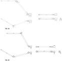
- FIG. 26 illustrates the folded configuration (on the right) of the medical fixation device 2001, and
- FIG. 29 illustrates several preferred unfolded configurations of the medical fixation device 2001.
- the medical fixation device 001 would typically span over a horizontal distance of 900mm to 1300mm, preferably 1000mm to 1200mm, more preferably 1110mm to 1130mm, and over a vertical distance of 250mm to 500mm, preferably 300mm to 450mm, more preferably 310mm to 420mm.
- the medical fixation device 2001 according to the second alternative embodiment has a maximum horizontal length of 1000mm to 2000mm, preferably 1400mm to 1600mm, more preferably 1450mm to 1550mm.
- the medical fixation device 2001 according to the second alternative embodiment has a length of 500mm to 1000mm, preferably 700mm to 900mm, more preferably 750mm to 850mm.
- the first elongate element 100, 1100, 2100 may be locked onto the second elongate element 200, 1200, 2200.
- This locking prevents unexpected unfolding of the device, thereby increasing the safety and the convenience of use of the medical fixation device.
- the first elongate element 100, 1100, 2100 can be locked onto the second elongate element 200, 1200, 2200 using a clamp 204.
- the medical fixation device 001 is designed and manufactured such that, when connected to an operating table as illustrated in FIG. 11 , it remains intact and maintains its position when forces are exerted thereon by the surgical instruments 600, such as surgical retractors 500.
- the surgical instruments 600 will primarily exert forces onto the first elongate element 100, in particular on the connection members 104 of the first elongate element, as illustrated in FIG. 11 .
- the forces exerted onto the first elongate element 100 will be transferred onto the other parts of the medical fixation device, and accumulate in the connection between the first elongate element 100 and the second elongate element 200, in particular the connection part 400, and in the base element 300.
- the first elongate element 100 in particular the first end 102 of the first elongate element, would typically displace by less than 10mm, preferably less than 7mm, more preferably less than 5mm when forces of 90N, in particular horizontal or vertical transversal forces, are exerted thereon by the surgical instruments, such as surgical retractors.
- the surgical instruments such as surgical retractors.
- displacement of a medical fixation device by less than 10mm would not be disturbing or distracting for the surgeon, in particular during orthopedic surgeries, more in particular during shoulder surgeries.
- the ability to withstand transversal forces of up to 90N means that even if the medical fixation device, in particular the first elongate element, was to carry the weight of an entire patient's arm (on average 3.5kg and 5.5kg for females and males respectively) or to withstand some forces exerted by a surgeon or a surgical assistant touching or leaning on the device, the medical fixation device would maintain its position with only a minimal displacement of the first elongate element and no displacement of the other elements.
- the first elongate element 1100, 2100, in particular the first end 1102, 2102 of the first elongate element would typically displace by less than 10mm, preferably less than 7mm, more preferably less than 5mm when forces of 90N, in particular horizontal or vertical transversal forces, are exerted thereon by the surgical instruments, such as surgical retractors.
- the medical fixation device 001, 1001, 2001 is covered with a sterile cover during surgery.
- the sterile cover may be a surgical drape, a sterile sleeve or any other sterile cover which is suitable for sterile covering an elongated medical device.
- the medical fixation device is covered with surgical drape during surgery.
- the medical fixation device is covered with a sterile sleeve, in particular a sterile sleeve with dimensions and shape corresponding to the dimensions and shape of the medical fixation device.
- the sterile sleeve is transparent.
- the medical fixation device according to embodiments of the present invention may be provided as a single component, or may be provided from a variety of separate components which together form a set of parts.
- the invention relates to a medical device set 003 comprising one or more medical fixation devices 001.
- the medical device set comprises one or more medical fixation bars 002 and one or more base elements 300.
- the medical device set 003 comprises medical fixation bars 002 in the folded configuration.
- the medical device set comprises two medical fixation bars and two base elements.
- the medical device set comprises one high-type medical fixation bar, one low-type medical fixation bar and two base elements, as illustrated in FIG. 12 .
- the medical device set 003 comprises one or more medical fixation devices 1001, 2001.
- the medical fixation devices 1001, 2001 are assembled.
- the medical device set 003 comprises medical fixation devices 1001, 2001 in the folded configuration, which is illustrated in FIG. 24 (on the left) and FIG. 26 .
- the medical device set 003 comprises two medical fixation devices 1001, 2001.
- the medical device set 003 comprises a left-sided medical fixation device 1001, 2001 and a right-sided medical fixation device 1001, 2001.
- An example of the medical device set 003 comprising one left-sided medical fixation device 2001 and one right-sided medical fixation device 2001 is illustrated in FIG. 26 .
- Whether the medical fixation device 1001, 2001 is side-specific ( FIG. 25 ) or not side-specific ( FIG. 24 ) depends on the base element design 1300, 2300 as described above.
- each medical fixation device 1001, 2001 can be unfolded into a high configuration (on the left, top) or a low configuration (on the left, bottom).
- the medical fixation devices comprised in one medical device set will be placed in one package.
- the package may be a wrapping, a box, a container or any other type of package which is suitable for packaging of medical devices.
- the invention in another aspect of the present invention, relates to a medical device system for keeping open a wound during surgery, wherein at least one of the components is a medical fixation device.
- the other components may for example be surgical instruments, such as surgical retractors, or a surgical drape.
- the invention relates to a medical fixation device, a medical device set or a medical device system for use in surgery.
- Embodiments of the present invention can be used in various types of surgery.
- the various types of surgery are known to those skilled in the art, and comprise but are not limited to, orthopedic surgery, trauma surgery, neurosurgery, plastic and reconstructive surgery, thoracic surgery, abdominal surgery, cardiovascular surgery, urological surgery, gynaecological surgery, otolaryngological and head and neck surgery, oral and maxillofacial surgery, eye surgery, etc.
- Orthopedic surgery comprises but is not limited to arm, leg and spine surgery.
- Arm surgery comprises, but is not limited to, shoulder surgery, upper arm surgery, lower arm surgery or hand surgery.
- Leg surgery comprises but is not limited to, hip surgery, upper leg surgery, lower leg surgery or foot surgery.
- Shoulder surgery comprises but is not limited to, total shoulder arthroplasty (including reverse total shoulder arthroplasty), shoulder trauma surgery (including fracture reposition), rotator cuff repair, repair of the shoulder joint (e.g. labral repair).
- the present invention concerns a medical fixation device for use in orthopedic surgery.
- the orthopedic surgery is arm surgery, preferably shoulder surgery, more preferably total shoulder arthroplasty or shoulder trauma surgery.
- Embodiments of the present invention can be used in various surgical positions.
- the various surgical positions are known to those skilled in the art, and comprise but are not limited to, supine position, beach chair position (i.e. sitting or semi-sitting position), prone or semi-prone position, lateral position, lithotomy position, Trendelenburg's Position, reverse Trendelenburg's Position, Jackknife position, etc.
- the present invention concerns a medical fixation device for use in beach chair position.
- the present invention concerns a medical fixation device for use in shoulder surgery, which is performed in beach chair position.
- the present invention concerns a medical device set for use in shoulder surgery.
- the shoulder surgery is performed in beach chair position.
- the medical device set for use in shoulder surgery comprises one high-type medical fixation bar 002, one low-type medical fixation bar 002 and two base elements 300.
- the medical device set for use in shoulder surgery comprises two medical fixation devices 1001, 2001, preferably a left-sided medical fixation device 1001, 2001 and a right-sided medical fixation device 1001, 2001.
- the present invention concerns a medical device system for use in shoulder surgery.
- the shoulder surgery is performed in beach chair position.
- the medical device system comprises one high-type medical fixation bar, one low-type medical fixation bar, two base elements and two or more surgical instruments.
- the medical device system comprises one high-type medical fixation bar, one low-type medical fixation bar, two base elements and one or more surgical drape.
- the medical device system comprises one high-type medical fixation bar, one low-type medical fixation bar, two base elements, one or more surgical retractors and one or more surgical drape.
- Embodiments of the present invention can furthermore be used for different types of patients, such as for example less muscular or more muscular, shorter or taller, skinnier or larger patients.
- the invention relates to a method for installation of the described medical fixation device, medical device set or medical device system.
- the present invention relates to a method for installation of the described medical fixation device, the method comprising the steps of:
- the medical fixation bar 002 may be the high-type medical fixation bar or the low-type medical fixation bar. If applicable, the medical fixation bar 002 may be slid into the base element 300 in the up-orientation or in the down-orientation. It is an advantage of the described installation method that the medical fixation device can be installed in a very easy and intuitive manner, and is straight-forward for new users.
- the present invention relates to a method for installation of the described medical fixation device, the method comprising the steps of:
- the present invention relates to a method for installation of the described medical fixation device, the method comprising the steps of:
- the present invention relates to a method for installation of the described medical fixation device 1001, 2001 the method comprising the steps of:
- the present invention relates to a method for installation of the described medical device set comprising one or more medical fixation devices.
- the steps of the method for installation of the medical fixation device are repeated for each medical fixation device present in the medical device set.
- the present invention relates to a method for installation of the described medical device set, the method comprising the steps of:
- the present invention relates to a method for installation of the described medical fixation device 1001, 2001, the method comprising the steps of:
- the present invention relates to a method for installation of the medical device set for use in shoulder surgery comprising one high-type medical fixation bar, one low-type medical fixation bar and two base elements.
- the high-type medical fixation bar is preferably placed in the up-orientation on the opposite side of the operated shoulder (contralateral side)
- the low-type medical fixation bar is preferably placed in the down-orientation of the side of the operated shoulder (ipsilateral side).
- the high-type medical fixation bar is preferably placed in the up-orientation on the left side of the patient, and the low-type medical fixation bar is preferably placed in the down-orientation of right the side of the patient, as illustrated in Fig. 11 .
- Such installation would maximize accessibility of the surgical site for the surgeon, and simultaneously enable optimal expansion of the edges of the incision by the surgical retractors connected to the described medical fixation devices.
- the present invention relates to a method for installation of the medical device set for use in shoulder surgery comprising two medical fixation devices 1001, 2001, preferably a left-sided medical fixation device and a right-sided medical fixation device.
- one medical fixation device 1001, 2001 is preferably placed in the high configuration on the opposite side of the operated shoulder (contralateral side), and one medical fixation device 1001, 2001 is preferably placed in the low configuration of the side of the operated shoulder (ipsilateral side).
- the present invention relates to a method for installation of the described medical device system.
- the steps of the method for installation of the medical fixation device are repeated for each medical fixation device comprised in the medical device system.
- the one or more medical fixation devices are covered with one or more sterile covers.
- the sterile cover is a surgical drape or a sterile sleeve.
- one or more surgical instruments are connected to the one or more medical fixation devices.
- the present invention relates to a method for installation of the medical device system comprising one high-type medical fixation bar, one low-type medical fixation bar, two base elements, one or more surgical instruments, such as retractors, and one or more surgical drapes.
- the present invention relates to a method for installation of the medical device system comprising two medical fixation devices 1001, 2001 one or more surgical instruments, such as retractors, and one or more surgical drapes.
Landscapes
- Health & Medical Sciences (AREA)
- Life Sciences & Earth Sciences (AREA)
- Surgery (AREA)
- Veterinary Medicine (AREA)
- Engineering & Computer Science (AREA)
- Biomedical Technology (AREA)
- Animal Behavior & Ethology (AREA)
- General Health & Medical Sciences (AREA)
- Public Health (AREA)
- Heart & Thoracic Surgery (AREA)
- Medical Informatics (AREA)
- Molecular Biology (AREA)
- Nuclear Medicine, Radiotherapy & Molecular Imaging (AREA)
- Oral & Maxillofacial Surgery (AREA)
- Pathology (AREA)
- Surgical Instruments (AREA)
Applications Claiming Priority (3)
| Application Number | Priority Date | Filing Date | Title |
|---|---|---|---|
| BE20235748A BE1031955B1 (nl) | 2023-09-13 | 2023-09-13 | Medisch fixatieapparaat om retractors te verbinden met een operatietafel |
| BE20245088A BE1031969B1 (nl) | 2023-09-13 | 2024-02-09 | Medisch fixatieapparaat om chirurgische instrumenten te verbinden met een operatietafel |
| US18/439,498 US20250082431A1 (en) | 2023-09-13 | 2024-02-12 | Medical fixation device for connecting surgical instruments to an operating table |
Publications (1)
| Publication Number | Publication Date |
|---|---|
| EP4523633A1 true EP4523633A1 (fr) | 2025-03-19 |
Family
ID=94686911
Family Applications (1)
| Application Number | Title | Priority Date | Filing Date |
|---|---|---|---|
| EP24200391.1A Pending EP4523633A1 (fr) | 2023-09-13 | 2024-09-13 | Dispositif de fixation médical pour connecter des instruments chirurgicaux à une table d'opération |
Country Status (2)
| Country | Link |
|---|---|
| US (1) | US20250082532A1 (fr) |
| EP (1) | EP4523633A1 (fr) |
Citations (9)
| Publication number | Priority date | Publication date | Assignee | Title |
|---|---|---|---|---|
| US4143652A (en) | 1976-01-29 | 1979-03-13 | Hans Meier | Surgical retaining device |
| US5586363A (en) | 1995-04-06 | 1996-12-24 | Fanuzzi; John M. | Indexing hinge |
| US5689999A (en) | 1995-08-18 | 1997-11-25 | Gunnell, Inc. | Adjustable rotary locking and unlocking apparatus |
| US5704900A (en) | 1995-10-20 | 1998-01-06 | Minnesota Scientific, Inc. | Method and apparatus for peritoneal distension |
| WO2001045601A2 (fr) | 1999-12-23 | 2001-06-28 | Guhl James F | Ensemble clamp ameliore pour systeme a dispositif de positionnement non invasif |
| US20110253653A1 (en) | 2008-08-22 | 2011-10-20 | Jen-Kun Chang | Support Mechanism for Operation Auxiliary Tools |
| US20130023735A1 (en) | 2011-05-18 | 2013-01-24 | Automated Medical Products Corporation | Telescoping surgical support and retractor system |
| US20130123911A1 (en) | 2011-11-15 | 2013-05-16 | St. Jude Medical, Cardiology Division, Inc. | Transapical collapsible valve reference fixture |
| WO2013092938A1 (fr) | 2011-12-21 | 2013-06-27 | Medenvision | Systèmes de rétracteurs chirurgicaux |
-
2024
- 2024-09-13 US US18/885,266 patent/US20250082532A1/en active Pending
- 2024-09-13 EP EP24200391.1A patent/EP4523633A1/fr active Pending
Patent Citations (9)
| Publication number | Priority date | Publication date | Assignee | Title |
|---|---|---|---|---|
| US4143652A (en) | 1976-01-29 | 1979-03-13 | Hans Meier | Surgical retaining device |
| US5586363A (en) | 1995-04-06 | 1996-12-24 | Fanuzzi; John M. | Indexing hinge |
| US5689999A (en) | 1995-08-18 | 1997-11-25 | Gunnell, Inc. | Adjustable rotary locking and unlocking apparatus |
| US5704900A (en) | 1995-10-20 | 1998-01-06 | Minnesota Scientific, Inc. | Method and apparatus for peritoneal distension |
| WO2001045601A2 (fr) | 1999-12-23 | 2001-06-28 | Guhl James F | Ensemble clamp ameliore pour systeme a dispositif de positionnement non invasif |
| US20110253653A1 (en) | 2008-08-22 | 2011-10-20 | Jen-Kun Chang | Support Mechanism for Operation Auxiliary Tools |
| US20130023735A1 (en) | 2011-05-18 | 2013-01-24 | Automated Medical Products Corporation | Telescoping surgical support and retractor system |
| US20130123911A1 (en) | 2011-11-15 | 2013-05-16 | St. Jude Medical, Cardiology Division, Inc. | Transapical collapsible valve reference fixture |
| WO2013092938A1 (fr) | 2011-12-21 | 2013-06-27 | Medenvision | Systèmes de rétracteurs chirurgicaux |
Also Published As
| Publication number | Publication date |
|---|---|
| US20250082532A1 (en) | 2025-03-13 |
Similar Documents
| Publication | Publication Date | Title |
|---|---|---|
| US6629944B2 (en) | Limb-positioning and traction device | |
| US9480616B2 (en) | Surgical table with pivotable femoral support | |
| EP2544772B1 (fr) | Positionneur de membre | |
| US9078635B2 (en) | Anterior hip replacement retractor assembly | |
| US8051515B1 (en) | Surgical bed clamp apparatus | |
| EP1659928B1 (fr) | Ecarteur multi-lame | |
| US8852090B2 (en) | System and method for retracting body tissue | |
| US7125380B2 (en) | Clamping apparatus and methods | |
| US9510812B2 (en) | Telescoping surgical support and retractor system | |
| CN103917212A (zh) | 手术台及配件 | |
| WO2011139900A2 (fr) | Support chirurgical téléscopique et système écarteur | |
| JP2015511865A (ja) | 身体組織を開創するためのシステムおよび方法 | |
| WO2014124498A1 (fr) | Dispositif de chirurgie de crête sacro-iliaque | |
| AU2020369890A1 (en) | Leg-holding device for hip or knee surgery and arrangement method thereof | |
| US20250082532A1 (en) | Medical fixation device for connecting surgical instruments to an operating table | |
| US20250082431A1 (en) | Medical fixation device for connecting surgical instruments to an operating table | |
| BE1031969B1 (nl) | Medisch fixatieapparaat om chirurgische instrumenten te verbinden met een operatietafel | |
| US20240366412A1 (en) | Apparatus for positioning a leg during surgery | |
| CN103284861B (zh) | 一种体位固定器 | |
| US20210205162A1 (en) | Surgical positioner apparatus, system, and method for securing to a side rail of support table | |
| US20060293568A1 (en) | Collapsible surgical tool bar |
Legal Events
| Date | Code | Title | Description |
|---|---|---|---|
| PUAI | Public reference made under article 153(3) epc to a published international application that has entered the european phase |
Free format text: ORIGINAL CODE: 0009012 |
|
| STAA | Information on the status of an ep patent application or granted ep patent |
Free format text: STATUS: THE APPLICATION HAS BEEN PUBLISHED |
|
| AK | Designated contracting states |
Kind code of ref document: A1 Designated state(s): AL AT BE BG CH CY CZ DE DK EE ES FI FR GB GR HR HU IE IS IT LI LT LU LV MC ME MK MT NL NO PL PT RO RS SE SI SK SM TR |
|
| STAA | Information on the status of an ep patent application or granted ep patent |
Free format text: STATUS: REQUEST FOR EXAMINATION WAS MADE |
|
| 17P | Request for examination filed |
Effective date: 20250919 |