EP4523637A1 - Scalpel à ultrasons médical, système de scalpel à ultrasons médical et système de scalpel à ultrasons assisté par robot - Google Patents
Scalpel à ultrasons médical, système de scalpel à ultrasons médical et système de scalpel à ultrasons assisté par robot Download PDFInfo
- Publication number
- EP4523637A1 EP4523637A1 EP23802554.8A EP23802554A EP4523637A1 EP 4523637 A1 EP4523637 A1 EP 4523637A1 EP 23802554 A EP23802554 A EP 23802554A EP 4523637 A1 EP4523637 A1 EP 4523637A1
- Authority
- EP
- European Patent Office
- Prior art keywords
- vibration
- handle
- central axis
- ultrasonic scalpel
- longitudinal central
- Prior art date
- Legal status (The legal status is an assumption and is not a legal conclusion. Google has not performed a legal analysis and makes no representation as to the accuracy of the status listed.)
- Pending
Links
Images





Classifications
-
- A—HUMAN NECESSITIES
- A61—MEDICAL OR VETERINARY SCIENCE; HYGIENE
- A61B—DIAGNOSIS; SURGERY; IDENTIFICATION
- A61B17/00—Surgical instruments, devices or methods
- A61B17/32—Surgical cutting instruments
- A61B17/3209—Incision instruments
- A61B17/3211—Surgical scalpels, knives; Accessories therefor
-
- A—HUMAN NECESSITIES
- A61—MEDICAL OR VETERINARY SCIENCE; HYGIENE
- A61B—DIAGNOSIS; SURGERY; IDENTIFICATION
- A61B17/00—Surgical instruments, devices or methods
- A61B17/32—Surgical cutting instruments
- A61B17/320068—Surgical cutting instruments using mechanical vibrations, e.g. ultrasonic
-
- A—HUMAN NECESSITIES
- A61—MEDICAL OR VETERINARY SCIENCE; HYGIENE
- A61B—DIAGNOSIS; SURGERY; IDENTIFICATION
- A61B17/00—Surgical instruments, devices or methods
- A61B17/16—Instruments for performing osteoclasis; Drills or chisels for bones; Trepans
-
- A—HUMAN NECESSITIES
- A61—MEDICAL OR VETERINARY SCIENCE; HYGIENE
- A61B—DIAGNOSIS; SURGERY; IDENTIFICATION
- A61B17/00—Surgical instruments, devices or methods
- A61B17/16—Instruments for performing osteoclasis; Drills or chisels for bones; Trepans
- A61B17/1613—Component parts
- A61B17/1628—Motors; Power supplies
-
- A—HUMAN NECESSITIES
- A61—MEDICAL OR VETERINARY SCIENCE; HYGIENE
- A61B—DIAGNOSIS; SURGERY; IDENTIFICATION
- A61B17/00—Surgical instruments, devices or methods
- A61B17/32—Surgical cutting instruments
- A61B17/320068—Surgical cutting instruments using mechanical vibrations, e.g. ultrasonic
- A61B2017/320072—Working tips with special features, e.g. extending parts
- A61B2017/320074—Working tips with special features, e.g. extending parts blade
- A61B2017/320075—Working tips with special features, e.g. extending parts blade single edge blade, e.g. for cutting
-
- A—HUMAN NECESSITIES
- A61—MEDICAL OR VETERINARY SCIENCE; HYGIENE
- A61B—DIAGNOSIS; SURGERY; IDENTIFICATION
- A61B17/00—Surgical instruments, devices or methods
- A61B17/32—Surgical cutting instruments
- A61B17/320068—Surgical cutting instruments using mechanical vibrations, e.g. ultrasonic
- A61B2017/320082—Surgical cutting instruments using mechanical vibrations, e.g. ultrasonic for incising tissue
-
- A—HUMAN NECESSITIES
- A61—MEDICAL OR VETERINARY SCIENCE; HYGIENE
- A61B—DIAGNOSIS; SURGERY; IDENTIFICATION
- A61B17/00—Surgical instruments, devices or methods
- A61B17/32—Surgical cutting instruments
- A61B17/320068—Surgical cutting instruments using mechanical vibrations, e.g. ultrasonic
- A61B2017/320098—Surgical cutting instruments using mechanical vibrations, e.g. ultrasonic with transverse or torsional motion
-
- A—HUMAN NECESSITIES
- A61—MEDICAL OR VETERINARY SCIENCE; HYGIENE
- A61B—DIAGNOSIS; SURGERY; IDENTIFICATION
- A61B34/00—Computer-aided surgery; Manipulators or robots specially adapted for use in surgery
- A61B34/30—Surgical robots
Definitions
- the present application relates to the field of medical instruments, and in particular to a medical ultrasonic scalpel, a medical ultrasonic scalpel system and a robotic-assisted ultrasonic scalpel system.
- common surgical tools include medical high-speed grinding drills, oscillating saws and other conventional tools. Bone cutting, drilling, or grinding can be performed with surgical tools to achieve the purpose of bone treatment.
- the present application is intended to solve at least one of the technical problems existing in the related art. To this end, it is an objective of the present application to propose a medical ultrasonic scalpel, a medical ultrasonic scalpel system and a robotic-assisted ultrasonic scalpel system, to improve the scope of application of the medical ultrasonic scalpel in surgery.
- an embodiment of the present application provides a medical ultrasonic scalpel, including: a handle having a handle longitudinal central axis, a first end of the handle being configured to be connected to a vibration source to receive a vibration generated by the vibration source; a shank having a shank longitudinal central axis, a first end of the shank being connected to a second end of the handle opposite to the first end of the handle; a blade having a blade longitudinal central axis, a first end of the blade being connected to a second end of the shank opposite to the first end of the shank, and a second end of the blade being provided with a cutting portion for cutting a tissue to be cut; and a composite vibration pattern generating portion provided on at least one of the handle and the shank and configured to convert the vibration received from the vibration source into a composite vibration of the cutting portion of the blade, the composite vibration including at least two of the following vibrations: 1) a longitudinal vibration parallel to at least one of the handle longitudinal central axis, the shank longitudinal central
- an embodiment of the present application provides a medical ultrasonic scalpel system, including a vibration source and a medical ultrasonic scalpel as described above, wherein the vibration source is connected to a first end of a handle of the medical ultrasonic scalpel, and is configured to generate a vibration.
- an embodiment of the present application provides a robotic-assisted ultrasonic scalpel system, including: a robotic-assisted surgical device and a medical ultrasonic scalpel system as described above, wherein the robotic-assisted surgical device is connected to a medical ultrasonic scalpel of the medical ultrasonic scalpel system to control movement of the medical ultrasonic scalpel.
- the composite vibration pattern generating portion is provided on at least one of the handle and the shank and can, under the action of a vibration source, drive a blade to generate a composite vibration including at least two of a longitudinal vibration, a torsional vibration and a bending vibration, such that the medical ultrasonic scalpel can generate a variety of vibrations to adapt to various types of surgeries, thereby improving the scope of application of the medical ultrasonic scalpel in surgery.
- 10 medical ultrasonic scalpel
- 100 handle
- 200 shank
- 300 blade
- 310 cutting portion
- 400 composite vibration pattern generating portion
- 410 first composite vibration pattern generating portion
- 411 inclined groove
- 420 second composite vibration pattern generating portion
- 421 lateral cutout
- 500 conical transition section
- 60 vibration source.
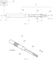
- FIG. 1 shows a structural diagram of a medical ultrasonic scalpel system according to an embodiment of the present application.
- the medical ultrasonic scalpel system includes a medical ultrasonic scalpel 10 and a vibration source 60.
- the medical ultrasonic scalpel 10 includes: a handle 100, a shank 200, a blade 300 and a composite vibration pattern generating portion 400.
- the handle 100 may be of a rod-like structure, and its cross-section may be in various shapes such as round or square.
- the handle 100 has a handle longitudinal central axis L1, and two opposite ends of the handle 100 along the handle longitudinal central axis L1 are a first end (left end in FIG. 1 ) and a second end (right end in FIG. 1 ) of the handle 100, respectively.
- the first end of the handle 100 may be connected to the vibration source 60 to receive a vibration generated by the vibration source 60.
- the shank 200 may be of an elongated strip-like structure, and its cross-section may be in various shapes such as square or oval.
- the shank 200 has a shank longitudinal central axis L2, and two opposite ends of the shank 200 along the shank longitudinal central axis L2 are a first end (left end in FIG. 1 ) and a second end (right end in FIG. 1 ) of the shank 200, respectively.
- the first end of the shank 200 is connected to the second end of the handle 100.
- the blade 300 may also be of an elongated strip-like structure, and its cross-section may be substantially in various shapes such as cross or diamond shapes.
- the blade 300 has a blade longitudinal central axis L3, and two opposite ends of the blade 300 along the blade longitudinal central axis L3 are a first end (left end in FIG. 1 ) and a second end (right end in FIG. 1 ) of the blade 300, respectively.
- the first end of the blade 300 is connected to the second end of the shank 200, and the second end of the blade 300 is provided with a cutting portion 310 for cutting a tissue to be cut.
- the tissue to be cut may be a bone, a blood vessel, and other tissues that need to be treated.
- the tissue to be cut is a bone.
- the cutting portion 310 may be located at the second end of the blade 300 facing away from the handle 100, and the cutting portion 310 may first come into contact with the bone during surgery to treat the bone.
- the handle 100, the shank 200 and the blade 300 may be connected in a sequence generally in a direction from left to right of FIG. 1 .
- the handle 100 may be of a cylindrical structure
- the shank 200 may be of a sheet-like structure.
- the cross-section of the shank 200 is substantially in the shape of a rectangle
- the cross-section of the blade 300 may be substantially in the shape of a diamond.
- the cross-sectional area of the handle 100 is the largest
- the cross-sectional area of the blade 300 is the smallest
- the cross-sectional area of the shank 200 is between that of the handle 100 and that of the blade 300.
- the relationship between the handle longitudinal central axis L1, the shank longitudinal central axis L2 and the blade longitudinal central axis L3 may be varied.
- the handle longitudinal central axis L1 and the shank longitudinal central axis L2 coincide with each other, and the blade longitudinal central axis L3 is offset by a predetermined distance from, or at a predetermined angle with respect to, the handle longitudinal central axis L1 and the shank longitudinal central axis L2. That is, the handle 100 and the shank 200 may extend in the same direction, and the blade longitudinal central axis L3 may be at a preset angle with respect to the shank longitudinal central axis L2, or the blade longitudinal central axis L3 may be parallel to, and offset by a predetermined distance from, the shank longitudinal central axis L2.
- the handle longitudinal central axis L1 and the blade longitudinal central axis L3 coincide with each other, and the shank longitudinal central axis L2 is offset by a predetermined distance from, or at a predetermined angle with respect to, the handle longitudinal central axis L1 and the blade longitudinal central axis L3. That is, the handle 100 and the blade 300 may extend in the same direction, and the shank longitudinal central axis L2 may be at a preset angle with respect to the blade longitudinal central axis L3, or the shank longitudinal central axis L2 may be parallel to, and offset by a predetermined distance from, the blade longitudinal central axis L3.
- the handle longitudinal central axis L1, the shank longitudinal central axis L2 and the blade longitudinal central axis L3 coincide with one another.
- the three may be connected in sequence in the same direction.
- the above various arrangements may enable the connection of the handle 100, the shank 200, and the blade 300.
- the preset angle may be greater than 0° and less than 180°, and the preset distance may be set according to the actual requirements.
- the medical ultrasonic scalpel 10 further includes a composite vibration pattern generating portion 400.
- the composite vibration pattern generating portion 400 is provided on at least one of the handle 100 and the shank 200, and the composite vibration pattern generating portion 400 is configured to convert the vibration received from the vibration source 60 into a composite vibration of the cutting portion 310 of the blade 300.
- the composite vibration includes at least two of the following vibrations:
- the composite vibration may include at least two of the longitudinal vibration, the torsional vibration, and the bending vibration.
- a combination of the longitudinal vibration and the torsional vibration may simulate the motion of a high-speed grinding drill or an oscillating saw, to realize the bone drilling or grinding treatment
- a combination of longitudinal motion and bending motion may simulate the motion of an oscillating saw or an osteotome, to realize the bone grinding or cutting treatment.
- a combination of the torsional vibration and the bending vibration may also realize the bone drilling or grinding treatment.
- a combination of the longitudinal vibration, the torsional vibration and the bending vibration may realize the bone drilling, cutting or grinding treatment.
- the composite vibration mode of the blade 300 may be selected according to the type of surgery to replace conventional surgical tools such as high-speed grinding drills or oscillating saws to treat the bone, so that the medical ultrasonic scalpel 10 can be applied to a variety of different types of surgeries, thereby improving the scope of application of the medical ultrasonic scalpel in surgery. Moreover, the surgery performed with the medical ultrasonic scalpel 10 will not cause damage to the soft tissue near the bone and is highly safe.
- the composite vibration of the blade 300 can be realized in a variety of ways.
- the structure of the medical ultrasonic scalpel 10 may be configured by means of the composite vibration pattern generating portion 400 such that the medical ultrasonic scalpel 10 converts a single type of vibration generated by the vibration source 60 into a composite vibration.
- the vibration source 60 may be configured such that the vibration source 60 may provide a variety of types of vibrations to the medical ultrasonic scalpel 10.
- the composite vibration pattern generating portion 400 may be formed by at least part of the handle 100 and the shank 200.
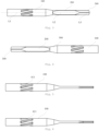
- FIG. 2 shows a schematic structural diagram of a medical ultrasonic scalpel according to an embodiment of the present application
- FIG. 3 is a front view of the medical ultrasonic scalpel of FIG. 2
- FIG. 4 is a rear view of the medical ultrasonic scalpel of FIG. 2
- FIG. 5 is a top view of the medical ultrasonic scalpel of FIG. 2
- FIG. 6 is a bottom view of the medical ultrasonic scalpel of FIG. 2
- FIG. 7 is a left side view of the medical ultrasonic scalpel of FIG. 2
- FIG. 8 is a right side view of the medical ultrasonic scalpel of FIG. 2 .
- the vibration source 60 may generate a longitudinal vibration.
- the composite vibration pattern generating portion 400 includes a first composite vibration pattern generating portion 410 provided in the handle 100.
- the first composite vibration pattern generating portion 410 is configured to convert a longitudinal vibration component of the vibration source 60 into the torsional vibration, so that the composite vibration (the superposition of the longitudinal vibration and the torsional vibration) of the cutting portion 310 of the blade 300 can be realized by configuring the structure of the medical ultrasonic scalpel 10.
- the first composite vibration pattern generating portion 410 may be of various structures.
- the first composite vibration pattern generating portion 410 may be a groove provided on the handle 100.
- the first composite vibration pattern generating portion 410 includes at least one inclined groove 411 provided on an outer periphery of the handle 100 at a first predetermined included angle with respect to the handle longitudinal central axis L1.
- the inclined groove 411 may be at the first predetermined included angle with respect to the handle longitudinal central axis L1. That is, an extension direction of the inclined groove 411 is not parallel to the handle longitudinal central axis L1.
- the at least one inclined groove 411 includes two or more inclined grooves 411 evenly distributed along the outer periphery of the handle 100. That is, the plurality of inclined grooves 411 may be equally spaced along the outer periphery of the handle 100.
- the first predetermined included angle may be greater than 0° and less than 180°.
- part of the longitudinal vibration component of the longitudinal vibration acts on the first composite vibration pattern generating portion 410. Since the inclined groove 411 is at the first predetermined included angle with respect to the handle longitudinal central axis L1, the part of the longitudinal vibration component is converted into the torsional vibration for rotation along the circumferential direction of the handle 100, so as to drive the cutting portion 310 to realize the torsional vibration. Moreover, since there is still part of the longitudinal vibration component that is not converted to the torsional vibration, the cutting portion 310 can still generate a longitudinal vibration under the action of the vibration source 60. That is, the cutting portion 310 of the blade 300 can realize a composite vibration of the longitudinal vibration and the torsional vibration.
- the first composite vibration pattern generating portion 410 may include at least one helical groove provided on the outer periphery of the handle 100 at the first predetermined included angle with respect to the handle longitudinal central axis L1.
- the helical groove may extend in the direction of a helix, and the first predetermined included angle may be a helix angle of the helix.
- the at least one helical groove includes two or more helical grooves evenly distributed along the outer periphery of the handle 100. That is, the plurality of helical grooves are arranged at intervals in the circumferential direction of the handle 100.
- the first composite vibration pattern generating portion 410 may alternatively include both at least one inclined groove 411 and at least one helical groove, and also enable the cutting portion 310 to realize a composite vibration of the longitudinal vibration and the torsional vibration. That is, the at least one inclined groove and the at least one helical groove include two or more inclined grooves and two or more helical grooves, respectively, evenly distributed along the outer periphery of the handle 100.
- the first composite vibration pattern generating portion 410 may be provided as a protrusion on the handle 100.
- the first composite vibration pattern generating portion 410 is at least one strip-like protrusion provided on the outer periphery of the handle 100 at the first predetermined included angle with respect to the handle longitudinal central axis L1.
- the inclined groove 411 may be at the first predetermined included angle with respect to the handle longitudinal central axis L1. That is, an extension direction of the strip-like protrusion is not parallel to the handle longitudinal central axis L1.
- the first predetermined included angle may be greater than 0° and less than 180°.
- the vibration source 60 When the vibration source 60 generates a longitudinal vibration, part of the longitudinal vibration component of the longitudinal vibration acts on the first composite vibration pattern generating portion 410. Since the strip-like protrusion is at the first predetermined included angle with respect to the handle longitudinal central axis L1, the part of the longitudinal vibration component is converted into the torsional vibration for rotation along the circumferential direction of the handle 100, so as to drive the cutting portion 310 to realize the torsional vibration. Moreover, since there is still part of the longitudinal vibration component that is not converted to the torsional vibration, the cutting portion 310 can still generate a longitudinal vibration under the action of the vibration source 60. That is, the cutting portion 310 of the blade 300 can realize a composite vibration of the longitudinal vibration and the torsional vibration.
- the first composite vibration pattern generating portion 410 is a helical protrusion provided on the outer periphery of the handle 100 at the first predetermined included angle with respect to the handle longitudinal central axis L1.
- the helical protrusion may extend in the direction of a helix, and the first predetermined included angle may be a helix angle of the helix.
- the plurality of helical grooves may be arranged at intervals along the handle longitudinal central axis L1, or along the circumferential direction of the handle 100.
- the first composite vibration pattern generating portion 410 may alternatively include both at least one strip-like protrusion and at least one helical protrusion, and also enable the cutting portion 310 to realize a composite vibration of the longitudinal vibration and the torsional vibration.
- the first composite vibration pattern generating portion 410 may include both the grooves and the protrusions provided on the handle 100.
- the above various structures of the first composite vibration pattern generating portion 410 can all convert the longitudinal vibration component into the torsional vibration, such that the cutting portion 310 realizes the composite vibration of the longitudinal vibration and the torsional vibration.
- FIG. 9 shows a schematic structural diagram of a medical ultrasonic scalpel according to another embodiment of the present application
- FIG. 10 is a front view of the medical ultrasonic scalpel of FIG. 9
- FIG. 11 is a rear view of the medical ultrasonic scalpel of FIG. 9
- FIG. 12 is a top view of the medical ultrasonic scalpel of FIG. 9
- FIG. 13 is a bottom view of the medical ultrasonic scalpel of FIG. 9
- FIG. 14 is a left side view of the medical ultrasonic scalpel of FIG. 9
- FIG. 15 is a right side view of the medical ultrasonic scalpel of FIG. 9 .
- the vibration source 60 may generate a longitudinal vibration.
- the composite vibration pattern generating portion 400 further includes a second composite vibration pattern generating portion 420 provided in the handle 100 or the shank 200.
- the second composite vibration pattern generating portion 420 is configured to convert a longitudinal vibration component of the vibration source 60 into the bending vibration, so that the composite vibration (the superposition of the longitudinal vibration and the bending vibration) of the cutting portion 310 of the blade 300 can be realized by configuring the structure of the medical ultrasonic scalpel 10.
- the second composite vibration pattern generating portion 420 may also be of various structures, and the second composite vibration pattern generating portion 420 is formed by at least one lateral cutout 421 of the shank 200.
- the lateral cutout 421 may be formed by removing a part of material from a side surface of the shank 200, and may be represented as a recess in the shank 200. There may also be one or more lateral cutouts 421, and the lateral cutouts 421 may be such that the shank 200 is of an asymmetric structure. For example, when there are a plurality of lateral cutouts, the plurality of lateral cutouts 421 are arranged at intervals along the longitudinal central axis L2 of the shank 200.
- the side surface may be understood as a lateral surface located between the first end and the second end of the shank 200.
- the shank 200 is of a flat sheet-like structure, and the lateral cutout 421 may be a notch provided at an edge of the shank 200.
- the second composite vibration pattern generating portion 420 is provided on the shank 200. In other embodiments, the second composite vibration pattern generating portion 420 may be provided on the handle 100. For example, the second composite vibration pattern generating portion 420 is formed by at least one lateral cutout of the handle 100.
- the second composite vibration pattern generating portion 420 may be formed by at least one lateral projection of the handle 100 or the shank 200.
- the lateral projection may be formed by adding a material to a side surface of the shank 200, and may be represented as a protruding portion on the shank 200.
- the plurality of lateral projections may be arranged at intervals along the longitudinal central axis L2 of the shank 200.
- the side surface may be understood as a lateral surface located between the first end and the second end of the shank 200.
- the lateral projection may be provided on the handle 100.
- the second composite vibration pattern generating portion 420 is formed by at least one lateral projection of the handle 100.
- the vibration source 60 When the vibration source 60 generates a longitudinal vibration, part of the longitudinal vibration component of the longitudinal vibration acts on the second composite vibration pattern generating portion 420. Since the handle 100 or the shank 200 has an asymmetrical eccentric structure due to the second composite vibration pattern generating portion 420, the structural forces on two sides of the handle longitudinal central axis L1 or the shank longitudinal central axis L2 are unbalanced, so that the medical ultrasonic scalpel 10 generates a bending vibration, so as to drive the cutting portion 310 to realize the bending vibration. Moreover, since there is still part of the longitudinal vibration component that is not converted to the bending vibration, the cutting portion 310 can still generate a longitudinal vibration under the action of the vibration source 60. That is, the cutting portion 310 of the blade 300 can realize a composite vibration of the longitudinal vibration and the bending vibration.
- the above various structures of the second composite vibration pattern generating portion 420 can all convert the longitudinal vibration component into the bending vibration, such that the cutting portion 310 realizes the composite vibration of the longitudinal vibration and the bending vibration.
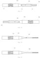
- FIG. 16 shows a schematic structural diagram of a medical ultrasonic scalpel according to yet another embodiment of the present application
- FIG. 17 is a front view of the medical ultrasonic scalpel of FIG. 16
- FIG. 18 is a rear view of the medical ultrasonic scalpel of FIG. 16
- FIG. 19 is a top view of the medical ultrasonic scalpel of FIG. 16
- FIG. 20 is a bottom view of the medical ultrasonic scalpel of FIG. 16
- FIG. 21 is a left side view of the medical ultrasonic scalpel of FIG. 16
- FIG. 22 is a right side view of the medical ultrasonic scalpel of FIG. 16 .
- the vibration source 60 may generate a longitudinal vibration.
- the composite vibration pattern generating portion 400 includes a first composite vibration pattern generating portion 410 provided in the handle 100 and a second composite vibration pattern generating portion 420 provided in the handle 100 or the shank 200.
- the first composite vibration pattern generating portion 410 is configured to convert the longitudinal vibration component of the vibration source 60 into the torsional vibration
- the second composite vibration pattern generating portion 420 is configured to convert the longitudinal vibration component of the vibration source 60 into the bending vibration, so that the composite vibration (the superposition of the longitudinal vibration, the torsional vibration and the bending vibration) of the cutting portion 310 of the blade 300 can be realized by configuring the structure of the medical ultrasonic scalpel 10.
- first composite vibration pattern generating portion 410 and the second composite vibration pattern generating portion 420 are the same as or similar to those in the above respective embodiments, and will not be described in more detail, and reference may be made specifically to the above embodiments.
- the longitudinal vibration may substantially include three parts of the longitudinal vibration component.
- a part of the longitudinal vibration component acts on the first composite vibration pattern generating portion 410. Since the first composite vibration pattern generating portion 410 is at the first predetermined included angle with respect to the handle longitudinal central axis L1, the part of the longitudinal vibration component is converted into the torsional vibration for rotation along the circumferential direction of the handle 100, so as to drive the cutting portion 310 to realize the torsional vibration.
- a second part of the longitudinal vibration component acts on the second composite vibration pattern generating portion 420. Since the handle 100 or the shank 200 has an asymmetrical eccentric structure due to the second composite vibration pattern generating portion 420, the structural forces on two sides of the handle longitudinal central axis L1 or the shank longitudinal central axis L2 are unbalanced, so that the medical ultrasonic scalpel 10 generates a bending vibration, so as to drive the cutting portion 310 to realize the bending vibration.
- a third part of the longitudinal vibration component is not converted to the torsional vibration or the bending vibration, so that the cutting portion 310 can still generate a longitudinal vibration under the action of the vibration source 60.
- the composite vibration pattern generating portion 400 enables the cutting portion 310 of the blade 300 to realize a composite vibration including the longitudinal vibration, the bending vibration and the torsional vibration.
- a transverse dimension of the handle 100 is greater than a transverse dimension of the shank 200, that is, the cross-sectional area of the handle 100 is greater than the cross-sectional area of the shank 200, and the second end of the handle 100 is connected to the first end of the shank 200 via a conical transition section 500.
- the conical transition section 500 can allow for a smooth transition between the handle 100 and the shank 200, increasing the strength of the medical ultrasonic scalpel 10.
- the composite vibration pattern generating portion 400 further includes a third composite vibration pattern generating portion provided in the conical transition section 500.
- the third composite vibration pattern generating portion is configured to convert a longitudinal vibration component of the vibration source 60 into the torsional vibration.
- the third composite vibration pattern generating portion may be of various structures.
- the third composite vibration pattern generating portion may be a groove provided on the conical transition section 500.
- the third composite vibration pattern generating portion includes at least one inclined groove provided on the outer periphery of the handle 100 at a second predetermined included angle with respect to the handle longitudinal central axis L1.
- the inclined groove may be at the second predetermined included angle with respect to the handle longitudinal central axis L1. That is, an extension direction of the inclined groove is not parallel to the handle longitudinal central axis L1.
- the inclined groove of the third composite vibration pattern generating portion differs from the inclined groove shown in FIG. 2 in that the inclined groove of the third composite vibration pattern generating portion is provided on a conical surface, and the distance between the inclined groove and a central line of the conical transition section 500 gradually decreases in a taper direction of the conical surface, whereas the inclined groove shown in FIG.
- the second predetermined included angle may be greater than 0° and less than 180°, which may be the same as or different from the first predetermined included angle.
- the third composite vibration pattern generating portion may include at least one helical groove provided on the outer periphery of the handle 100 at the second predetermined included angle with respect to the handle longitudinal central axis L1.
- the helical groove may extend in the direction of a conical helix, and the first predetermined included angle may be a helix angle of the conical helix.
- the third composite vibration pattern generating portion may alternatively include both at least one inclined groove and at least one helical groove, and also enable the cutting portion 310 to realize a composite vibration of the longitudinal vibration and the torsional vibration. That is, the at least one inclined groove and the at least one helical groove include two or more inclined grooves and two or more helical grooves, respectively, evenly distributed along the outer periphery of the conical transition section 500.
- the third composite vibration pattern generating portion may be provided as a protrusion on the conical transition section 500.
- the third composite vibration pattern generating portion is at least one strip-like protrusion provided on the outer periphery of the handle 100 at the second predetermined included angle with respect to the handle longitudinal central axis L1.
- the strip-like protrusion may be at the second predetermined included angle with respect to the handle longitudinal central axis L1. That is, an extension direction of the strip-like protrusion is not parallel to the handle longitudinal central axis L1.
- the distance between the strip-like protrusion and the central line of the conical transition section 500 gradually decreases in the taper direction of the conical surface.
- the arrangement of the strip-like protrusion can be referred to the arrangement of the inclined groove, and will not be described in more detail.
- the third composite vibration pattern generating portion may include at least one helical protrusion provided on the outer periphery of the handle 100 at the second predetermined included angle with respect to the handle longitudinal central axis L1.
- the helical protrusion may extend in the direction of a conical helix, and the second predetermined angle may be a helix angle of the conical helix.
- the arrangement of the helical protrusion can be referred to the arrangement of the helical groove, and will not be described in more detail.
- the third composite vibration pattern generating portion may alternatively include both at least one strip-like protrusion and at least one helical protrusion, and also enable the cutting portion 310 to realize a composite vibration of the longitudinal vibration and the torsional vibration.
- the vibration source 60 When the vibration source 60 generates a longitudinal vibration, part of the longitudinal vibration component of the longitudinal vibration acts on the third composite vibration pattern generating portion. Since the third composite vibration pattern generating portion is at the second predetermined included angle with respect to the handle longitudinal central axis L1, the part of the longitudinal vibration component is converted into the torsional vibration for rotation along the circumferential direction of the conical transition section, so as to drive the cutting portion 310 to realize the torsional vibration.
- the cutting portion 310 can still generate a longitudinal vibration under the action of the vibration source 60. That is, the cutting portion 310 of the blade 300 can realize a composite vibration of the longitudinal vibration and the torsional vibration.
- the composite vibration pattern generating portion 400 may include at least one of the first composite vibration pattern generating portion 410, the second composite vibration pattern generating portion 420 and the third composite vibration pattern generating portion, which may be selected according to a desired vibration mode.
- the vibration source 60 includes an ultrasonic transducer.
- the ultrasonic transducer may be connected to the first end of the handle 100, and can generate a longitudinal vibration and/or a torsional vibration.
- the ultrasonic transducer may enable a torsional motion and convert the torsional motion into a composite vibration including the torsional vibration by a change in the structure of the medical ultrasonic scalpel 10.
- FIG. 23 shows a schematic structural diagram of a medical ultrasonic scalpel according to yet another embodiment of the present application
- FIG. 24 is a front view of the medical ultrasonic scalpel of FIG. 23
- FIG. 25 is a rear view of the medical ultrasonic scalpel of FIG. 23
- FIG. 26 is a top view of the medical ultrasonic scalpel of FIG. 23
- FIG. 27 is a bottom view of the medical ultrasonic scalpel of FIG. 23
- FIG. 28 is a left side view of the medical ultrasonic scalpel of FIG. 23
- FIG. 29 is a right side view of the medical ultrasonic scalpel of FIG. 23 .
- the ultrasonic transducer may generate a longitudinal vibration and a torsional vibration, and at least a part of the handle 100 and the shank 200 constitutes the composite vibration pattern generating portion.
- the ultrasonic transducer may generate a longitudinal vibration and a torsional vibration, and at least a part of the handle 100 and the shank 200 constitutes the composite vibration pattern generating portion.
- no special modification is made to the structure of the medical ultrasonic scalpel 10, and the longitudinal vibration and the torsional rotation, i.e. the composite vibration, of the cutting portion 310 are realized by virtue of a variety of vibrations generated by the ultrasonic transducer.
- the ultrasonic transducer may simultaneously generate a torsional vibration and a longitudinal vibration, and the structure of the medical ultrasonic scalpel 10 may be modified.
- the composite vibration pattern generating portion 400 may include a second composite vibration pattern generating portion 420, so as to realize a composite vibration including the longitudinal vibration, the torsional vibration and the bending vibration.
- the vibration mode of the ultrasonic transducer and the structure of the composite vibration pattern generating portion 400 can be combined according to the requirements, the ultrasonic transducer generates at least one of the torsional vibration and the longitudinal vibration, and the composite vibration pattern generating portion 400 may include at least one of the first composite vibration pattern generating portion 410, the second composite vibration pattern generating portion 420, and the third composite vibration pattern generating portion, to realize a composite vibration of the cutting portion 310.
- FIG. 30 is a diagram showing the deformation of the medical ultrasonic scalpel according to the embodiment of the present application during longitudinal vibration.
- the dotted lines show a state of the medical ultrasonic scalpel 10 before a vibration is generated
- the solid lines show a state when the length of the medical ultrasonic scalpel 10 is increased while a longitudinal vibration is generated. Since the change in the width of the medical ultrasonic scalpel 10 is not significant during the longitudinal vibration, its overall profile is not shown in FIG. 30 , but only the part with an increased length is shown.
- the longitudinal vibration of the medical ultrasonic scalpel 10 makes it possible to realize a bone cutting treatment.
- FIG. 31 is a diagram showing the deformation of the medical ultrasonic scalpel according to the embodiment of the present application during bending vibration.
- the dotted lines show a state of the medical ultrasonic scalpel 10 before a vibration is generated
- the solid lines show a state when the medical ultrasonic scalpel 10 generates a longitudinal vibration.
- the second composite vibration pattern generating portion 420 can change the longitudinal vibration into a bending vibration, such that the medical ultrasonic scalpel 10 is bent, and the length thereof is increased, that is, the cutting portion 310 generates a composite vibration including the longitudinal vibration and the bending vibration.
- the medical ultrasonic scalpel 10 can realize bone cutting and grinding treatments.
- an embodiment of the present application also provide a medical ultrasonic scalpel system, including a vibration source 60 and a medical ultrasonic scalpel 10.
- the vibration source 60 is connected to a first end of a handle 100 of the medical ultrasonic scalpel 10, and the vibration source 60 is configured to generate a vibration.
- vibration source 60 and the medical ultrasonic scalpel 10 are the same as those in the above various embodiments and will not be described in more detail herein, and reference may be made specifically to the above various embodiments.
- the medical ultrasonic scalpel system provided in this embodiment enables the medical ultrasonic scalpel to generate a variety of vibrations to adapt to various types of surgeries, thereby improving the scope of application of the medical ultrasonic scalpel in surgery.
- An embodiment of the present application also provides a robotic-assisted ultrasonic scalpel system, including: a robotic-assisted surgical device and a medical ultrasonic scalpel system.
- the robotic-assisted surgical device is connected to a medical ultrasonic scalpel of the medical ultrasonic scalpel system to control movement of the medical ultrasonic scalpel.
- the robotic-assisted surgical device may include a robot capable of moving in multiple degrees of freedom, and precise control of the surgery can be realized by operating the medical ultrasonic scalpel by the robot.
- orientations or positional relationships or dimensions denoted by the terms such as “center”, “longitudinal”, “transverse”, “length”, “width”, “thickness”, “upper”, “lower”, “front”, “rear”, “left”, “right”, “vertical”, “horizontal”, “top”, “bottom”, “inner”, “outer”, “clockwise”, “counterclockwise”, “axial”, “radial” and “circumferential”, are the orientations or positional relationships or dimensions shown on the basis of the drawings, and these terms are used merely for ease of description, rather than indicating or implying that the device or element referred to must have particular orientations and be constructed and operated in the particular orientations, and therefore should not be construed as limiting the scope of protection of the present application.
- first”, “second” and “third” are merely for descriptive purposes and should not be construed as indicating or implying relative importance or implicitly indicating the number of technical features indicated. Thus, the features defined with “first”, “second” and “third” may explicitly or implicitly include one or more features.
- the term “plurality of” means two or more, unless specifically and specifically limited otherwise.
- connection should be interpreted broadly, for example, either fixed or detachable connection, or integration; may be a mechanical connection, or an electrical connection, or communication; and may be a direct connection or an indirect connection by means of an intermediate medium, or may be internal communication between two elements or interaction between the two elements.
- fixing should be interpreted broadly, for example, either fixed or detachable connection, or integration; may be a mechanical connection, or an electrical connection, or communication; and may be a direct connection or an indirect connection by means of an intermediate medium, or may be internal communication between two elements or interaction between the two elements.
- the expression of the first feature being “above” or “below” the second feature may include the case where the first feature is in direct contact with the second feature, and may also include the case where the first and second features are not in direct contact but are contacted via another feature therebetween.
- the first feature being “over”, “above” or “on” the second feature includes the case where the first feature is directly or obliquely above the second feature, or merely indicates that the first feature is at a higher level than the second feature.
- the first feature being “below”, “under” or “beneath” the second feature includes the case where the first feature is directly or obliquely below the second feature, or merely indicates that the first feature is at a lower level than the second feature.
Landscapes
- Health & Medical Sciences (AREA)
- Surgery (AREA)
- Life Sciences & Earth Sciences (AREA)
- Engineering & Computer Science (AREA)
- Biomedical Technology (AREA)
- Public Health (AREA)
- Veterinary Medicine (AREA)
- Nuclear Medicine, Radiotherapy & Molecular Imaging (AREA)
- General Health & Medical Sciences (AREA)
- Heart & Thoracic Surgery (AREA)
- Medical Informatics (AREA)
- Molecular Biology (AREA)
- Animal Behavior & Ethology (AREA)
- Dentistry (AREA)
- Oral & Maxillofacial Surgery (AREA)
- Orthopedic Medicine & Surgery (AREA)
- Mechanical Engineering (AREA)
- Robotics (AREA)
- Surgical Instruments (AREA)
Applications Claiming Priority (3)
| Application Number | Priority Date | Filing Date | Title |
|---|---|---|---|
| CN202221138828.XU CN217408915U (zh) | 2022-05-11 | 2022-05-11 | 医用超声刀、医用超声刀系统及机器人辅助超声刀系统 |
| CN202210515289.5A CN114886513A (zh) | 2022-05-11 | 2022-05-11 | 医用超声刀、医用超声刀系统及机器人辅助超声刀系统 |
| PCT/CN2023/086623 WO2023216778A1 (fr) | 2022-05-11 | 2023-04-06 | Scalpel à ultrasons médical, système de scalpel à ultrasons médical et système de scalpel à ultrasons assisté par robot |
Publications (1)
| Publication Number | Publication Date |
|---|---|
| EP4523637A1 true EP4523637A1 (fr) | 2025-03-19 |
Family
ID=88729641
Family Applications (1)
| Application Number | Title | Priority Date | Filing Date |
|---|---|---|---|
| EP23802554.8A Pending EP4523637A1 (fr) | 2022-05-11 | 2023-04-06 | Scalpel à ultrasons médical, système de scalpel à ultrasons médical et système de scalpel à ultrasons assisté par robot |
Country Status (7)
| Country | Link |
|---|---|
| US (1) | US20250204945A1 (fr) |
| EP (1) | EP4523637A1 (fr) |
| JP (1) | JP2025514186A (fr) |
| KR (1) | KR20250009507A (fr) |
| AU (1) | AU2023267637B2 (fr) |
| MX (1) | MX2024013698A (fr) |
| WO (1) | WO2023216778A1 (fr) |
Families Citing this family (1)
| Publication number | Priority date | Publication date | Assignee | Title |
|---|---|---|---|---|
| CN119138974B (zh) * | 2024-09-19 | 2025-05-16 | 苏州勤灏精密机械有限公司 | 基于多自由度超声刀的切割止血同步运行刀头组件 |
Family Cites Families (27)
| Publication number | Priority date | Publication date | Assignee | Title |
|---|---|---|---|---|
| CA2276316C (fr) * | 1998-06-29 | 2008-02-12 | Ethicon Endo-Surgery, Inc. | Methode d'equilibrage de lames chirurgicales ultrasonores asymetriques |
| US6423082B1 (en) * | 2000-03-31 | 2002-07-23 | Ethicon Endo-Surgery, Inc. | Ultrasonic surgical blade with improved cutting and coagulation features |
| US6514267B2 (en) * | 2001-03-26 | 2003-02-04 | Iep Pharmaceutical Devices Inc. | Ultrasonic scalpel |
| WO2003095028A1 (fr) * | 2002-05-13 | 2003-11-20 | Axya Medical, Inc. | Systemes ultrasonores de coupe et de coagulation de tissus mous |
| JP2004275592A (ja) * | 2003-03-18 | 2004-10-07 | Miwatec:Kk | 複合振動超音波ハンドピ−ス |
| US20050234484A1 (en) * | 2004-02-27 | 2005-10-20 | Houser Kevin L | Ultrasonic surgical blade having transverse and longitudinal vibration |
| GB0426503D0 (en) * | 2004-12-02 | 2005-01-05 | Orthosonics Ltd | Improved osteotome |
| US7621930B2 (en) * | 2006-01-20 | 2009-11-24 | Ethicon Endo-Surgery, Inc. | Ultrasound medical instrument having a medical ultrasonic blade |
| US20090069830A1 (en) * | 2007-06-07 | 2009-03-12 | Piezo Resonance Innovations, Inc. | Eye surgical tool |
| WO2009111436A2 (fr) * | 2008-03-06 | 2009-09-11 | Eilaz Babaev | Scalpel ultrasonore |
| US20090270891A1 (en) * | 2008-04-18 | 2009-10-29 | Jean Michael Beaupre | Balanced ultrasonic curved blade |
| JP4898980B2 (ja) * | 2010-01-21 | 2012-03-21 | オリンパスメディカルシステムズ株式会社 | 外科処置装置 |
| DE102012200666B4 (de) * | 2012-01-18 | 2014-09-11 | Söring GmbH | Sonotrode, chirurgisches Instrument mit einer Sonotrode sowie Herstellungsverfahren für eine Sonotrode |
| CN104349737B (zh) * | 2012-06-06 | 2016-09-07 | 奥林巴斯株式会社 | 超声波探头及超声波探头的制造方法 |
| WO2015029518A1 (fr) * | 2013-08-29 | 2015-03-05 | オリンパスメディカルシステムズ株式会社 | Dispositif de traitement de prise et unité de prise |
| CN105310746B (zh) * | 2015-07-22 | 2018-04-24 | 以诺康医疗科技(苏州)有限公司 | 一种同时提高切割和止血效果的超声手术刀 |
| EP3512443B1 (fr) * | 2016-09-16 | 2020-04-22 | Stryker European Holdings I, LLC | Pointe pour un outil chirurgical à ultrasons ayant des bords de coupe cémentés et son procédé de fabrication |
| CN107582128A (zh) * | 2017-09-29 | 2018-01-16 | 北京水木天蓬医疗技术有限公司 | 一种超声骨刀刀头 |
| CN107595368B (zh) * | 2017-10-19 | 2024-04-30 | 以诺康医疗科技(苏州)有限公司 | 一种超声波手术刀头、刀杆及超声波手术刀 |
| US20200022720A1 (en) * | 2017-12-07 | 2020-01-23 | Beijing Smtp Technology Co., Ltd. | Ultrasonic scalpel bit, ultrasonic vibration propagation assembly and ultrasonic hemostasis and cutting system |
| CN109620415B (zh) * | 2019-02-14 | 2024-03-26 | 北京水木天蓬医疗技术有限公司 | 机器人辅助超声骨动力系统 |
| CN110141308B (zh) * | 2019-05-10 | 2021-08-27 | 天津大学 | 一种具有增强止血能力的超声刀 |
| US12171454B2 (en) * | 2021-02-25 | 2024-12-24 | Olympus Corporation | Curved ultrasonic transmission member having improved vibration control |
| CN217408915U (zh) * | 2022-05-11 | 2022-09-13 | 北京水木天蓬医疗设备有限公司 | 医用超声刀、医用超声刀系统及机器人辅助超声刀系统 |
| CN114886513A (zh) * | 2022-05-11 | 2022-08-12 | 北京水木天蓬医疗设备有限公司 | 医用超声刀、医用超声刀系统及机器人辅助超声刀系统 |
| CN115500900B (zh) * | 2022-09-13 | 2024-03-19 | 以诺康医疗科技(苏州)有限公司 | 一种用于超声手术刀的切削部、过渡部及超声手术刀 |
| US20240197354A1 (en) * | 2022-12-19 | 2024-06-20 | Medtronic Ps Medical, Inc. | Irrigated ultrasonic device with features for dissecting dense tissue |
-
2023
- 2023-04-06 KR KR1020247041221A patent/KR20250009507A/ko active Pending
- 2023-04-06 US US18/859,052 patent/US20250204945A1/en active Pending
- 2023-04-06 JP JP2024563298A patent/JP2025514186A/ja active Pending
- 2023-04-06 WO PCT/CN2023/086623 patent/WO2023216778A1/fr not_active Ceased
- 2023-04-06 EP EP23802554.8A patent/EP4523637A1/fr active Pending
- 2023-04-06 AU AU2023267637A patent/AU2023267637B2/en active Active
-
2024
- 2024-11-05 MX MX2024013698A patent/MX2024013698A/es unknown
Also Published As
| Publication number | Publication date |
|---|---|
| WO2023216778A1 (fr) | 2023-11-16 |
| US20250204945A1 (en) | 2025-06-26 |
| AU2023267637A1 (en) | 2024-11-21 |
| JP2025514186A (ja) | 2025-05-02 |
| AU2023267637B2 (en) | 2026-02-12 |
| KR20250009507A (ko) | 2025-01-17 |
| MX2024013698A (es) | 2024-12-06 |
Similar Documents
| Publication | Publication Date | Title |
|---|---|---|
| EP1323481B1 (fr) | Couplage des vibrations à une pièce à main ultrasonique | |
| JP6534996B2 (ja) | 超音波器具及びその製造方法 | |
| EP2967593B1 (fr) | Foret chirurgical ultrasonore | |
| US8430897B2 (en) | Ultrasonic wound debrider probe and method of use | |
| JP6924704B2 (ja) | 線維組織除去のための超音波チップを有する外科器具 | |
| US20050177184A1 (en) | Torsional dissection tip | |
| JP2009261667A (ja) | 超音波ホーン及び超音波ハンドピース | |
| US12514595B2 (en) | Method and apparatus to reduce vibration | |
| WO2008048386A2 (fr) | Sonde ultrasonique de débridement de plaies et procédé d'utilisation | |
| EP2119403A1 (fr) | Ostéotome pour la chirurgie osseuse par ultrasons, en particulier pour la chirurgie maxillofaciale, dentaire et orthopédique | |
| EP4523637A1 (fr) | Scalpel à ultrasons médical, système de scalpel à ultrasons médical et système de scalpel à ultrasons assisté par robot | |
| KR20260030935A (ko) | 초음파 메스 블레이드 | |
| CN217408915U (zh) | 医用超声刀、医用超声刀系统及机器人辅助超声刀系统 | |
| US20260007429A1 (en) | Medical Ultrasonic Scalpel, Medical Ultrasonic Scalpel System, and Robot-Assisted Ultrasonic Scalpel System | |
| CN114886513A (zh) | 医用超声刀、医用超声刀系统及机器人辅助超声刀系统 | |
| CN211156054U (zh) | 一种医用工作尖、超声骨刀机和超声洁牙机 | |
| JP2002209906A (ja) | 超音波ハンドピ−ス | |
| JP2004275592A (ja) | 複合振動超音波ハンドピ−ス | |
| WO2021019852A1 (fr) | Procédé pour faire vibrer un appareil de vibration haute fréquence de type à pièce à main | |
| CA2711770C (fr) | Sonde a ultrasons de debridement de plaies et procede d'utilisation | |
| JPS62176445A (ja) | ハンドピ−ス |
Legal Events
| Date | Code | Title | Description |
|---|---|---|---|
| STAA | Information on the status of an ep patent application or granted ep patent |
Free format text: STATUS: THE INTERNATIONAL PUBLICATION HAS BEEN MADE |
|
| PUAI | Public reference made under article 153(3) epc to a published international application that has entered the european phase |
Free format text: ORIGINAL CODE: 0009012 |
|
| STAA | Information on the status of an ep patent application or granted ep patent |
Free format text: STATUS: REQUEST FOR EXAMINATION WAS MADE |
|
| 17P | Request for examination filed |
Effective date: 20241211 |
|
| AK | Designated contracting states |
Kind code of ref document: A1 Designated state(s): AL AT BE BG CH CY CZ DE DK EE ES FI FR GB GR HR HU IE IS IT LI LT LU LV MC ME MK MT NL NO PL PT RO RS SE SI SK SM TR |
|
| DAV | Request for validation of the european patent (deleted) | ||
| DAX | Request for extension of the european patent (deleted) | ||
| RIC1 | Information provided on ipc code assigned before grant |
Ipc: A61B 17/32 20060101AFI20260309BHEP Ipc: A61B 17/16 20060101ALI20260309BHEP Ipc: A61B 34/30 20160101ALI20260309BHEP Ipc: A61B 34/00 20160101ALI20260309BHEP |