EP4523968A1 - Trennwandvorrichtung mit mitteln zur ermöglichung von drei verwendungskonfigurationen - Google Patents
Trennwandvorrichtung mit mitteln zur ermöglichung von drei verwendungskonfigurationen Download PDFInfo
- Publication number
- EP4523968A1 EP4523968A1 EP24199873.1A EP24199873A EP4523968A1 EP 4523968 A1 EP4523968 A1 EP 4523968A1 EP 24199873 A EP24199873 A EP 24199873A EP 4523968 A1 EP4523968 A1 EP 4523968A1
- Authority
- EP
- European Patent Office
- Prior art keywords
- partition wall
- arrangement
- movable partition
- vehicle
- configuration
- Prior art date
- Legal status (The legal status is an assumption and is not a legal conclusion. Google has not performed a legal analysis and makes no representation as to the accuracy of the status listed.)
- Pending
Links
Images


Classifications
-
- B—PERFORMING OPERATIONS; TRANSPORTING
- B60—VEHICLES IN GENERAL
- B60R—VEHICLES, VEHICLE FITTINGS, OR VEHICLE PARTS, NOT OTHERWISE PROVIDED FOR
- B60R5/00—Compartments within vehicle body primarily intended or sufficiently spacious for trunks, suit-cases, or the like
- B60R5/006—Compartments within vehicle body primarily intended or sufficiently spacious for trunks, suit-cases, or the like stowing or holding means for elongated articles, e.g. skis inside vehicles
-
- B—PERFORMING OPERATIONS; TRANSPORTING
- B60—VEHICLES IN GENERAL
- B60R—VEHICLES, VEHICLE FITTINGS, OR VEHICLE PARTS, NOT OTHERWISE PROVIDED FOR
- B60R21/00—Arrangements or fittings on vehicles for protecting or preventing injuries to occupants or pedestrians in case of accidents or other traffic risks
- B60R21/02—Occupant safety arrangements or fittings, e.g. crash pads
- B60R21/026—Rigid partitions inside vehicles, e.g. between passengers and load compartments
Definitions
- the loading compartment is in communication with the passenger compartment of the vehicle, so that a partitioning device is used to protect the occupants in the event of a transported object being thrown, particularly in the event of an accident.
- Known partitioning devices may comprise at least one fixed wall, or even one fixed wall located behind the driver's seat and one fixed wall located behind the passenger seat.
- the fixed part located behind the passenger seat comprises an access hatch closing an opening made through the wall. Even if such an opening allows objects having a length greater than that of the loading compartment to move through the passenger compartment, the size of the hatch does not allow the loading of bulky objects into the passenger compartment.
- vehicles without a B-pillar are also known, which are greatly appreciated due to their enlarged opening compared to vehicles with a B-pillar delimiting two lateral openings, each closed by an opening.
- the openings can be one of the front hinged type, the other of the rear sliding type for example.
- the enlarged opening makes it possible to load bulky objects from the lateral side of the vehicle, which some users seek.
- This advantage finds a limit in the case of a vehicle with an enlarged opening and a partition wall, in particular because the partition wall includes an external lateral edge which cuts into two parts the access to the interior of the vehicle through the enlarged opening, thus making it impossible to load and transport bulky objects both through the loading compartment and the passenger compartment.
- partitioning devices may comprise a fixed part and a movable part, the latter often being articulated around a vertical axis such that the movable part is able to take an open position which is perpendicular to the fixed part.
- the moving part is arranged laterally to the driver, which obstructs his field of vision, in particular making side rearview impossible.
- the subject of the invention consists of an arrangement of a vehicle body comprising a partitioning device making it possible to separate, load and transport objects through loading and passenger compartment areas of the vehicle delimited in particular by a floor, the vehicle comprising a lateral opening capable of being closed by at least one opening, in particular by two directly adjacent openings in the closed position, at least one of the openings being glazed, the partitioning device comprising a movable partition wall.
- the movable partition wall comprises an upper part connected to a first articulation device making it possible to rotate about a vertical axis relative to the vehicle body, a lower part being connected to a second articulation device making it possible to rotate about a transverse axis relative to the upper part, the transverse axis of rotation being located approximately at a height of the floor defined according to a window frame of one of the openings, in particular according to a height of a window sill of one of the openings.
- the invention also relates to a vehicle comprising at least one opening on one of these body sides, a front door, a rear door, the opening being capable of being closed by the front and rear doors respectively in closed position, and includes the arrangement having some or all of the features previously described.
- X is the longitudinal front-rear direction of the vehicle directed towards the rear
- Y is the transverse right-left direction to the vehicle, which is horizontal and perpendicular to X, directed towards the right
- Z is the vertical direction directed towards the top.
- front, “rear”, “right”, “left”, “horizontal”, “vertical”, “upper” and “lower” relate to the vehicle or a part thereof and are defined in relation to the direction of movement of the vehicle.
- a vehicle 2 which is of the utility vehicle type with a rear loading area, here shown sheet metal, and a front area intended for at least one occupant, in particular the driver.
- the front area defines the cockpit of the vehicle which is made accessible by the front opening 5, which is preferably of the type of a swinging side door, in particular by a rotating articulation device consisting of hinges connecting the front door 5 to the front pillar of the body of the vehicle 2.
- the swinging side door 5 is provided with a window through which the driver's vision operates.
- the window moves through a window frame 50.
- the rear area defines the loading compartment which is made accessible by the rear opening 6, which is preferably of the type of a sliding side door along the longitudinal axis X of the vehicle.
- Access to the front and rear areas is made possible by an opening 4, which is then unique, and closed by the front hinged doors 5 and the rear sliding doors 6.
- FIG.2 illustrates the body of the vehicle 2 comprising the partitioning device 3 which consists of a fixed partition wall 33, preferably arranged at the rear of the driver's seat (not shown).
- the fixed partition wall extends along the transverse axis Y. It is extended by a movable partition wall 30 which consists of an upper part 31 and a lower part 32, shown here one above the other.
- the movable partition wall 30 is held in place by a locking device 60 which aims to fix it at the level of the floor 7.
- the locking device 60 may be of the type of a vertically sliding rod engaging an opening made in the floor.
- the partitioning device 3 in the CS separation configuration ensures total partitioning of the opening between the front part defining the passenger compartment area 22 and the rear part defining the loading area 21.
- FIG. 3 represents the loading configuration CC of the partitioning device 3 according to which the movable partition wall 30 is pivoted forwards around an axis Z.
- the rotation angle is approximately 90°, such that the movable partition wall 30 extends substantially perpendicular to the fixed partition wall 33. In this position, the driver's field of vision and/or rear vision is completely obstructed so that the configuration is limited to the loading time where accessibility to the interior of the vehicle comprising a single opening 4 is increased.
- the partitioning device 3 is provided with a hinge device 41 which makes it possible to rotate the movable partition wall 30 around an axis Z.
- the hinge device 41 may comprise a vertical rod securely connected to the upper part 31.
- the inner edge of the upper part 31 comprises the vertical rod which extends projecting downwards until it comes into rotational connection with the floor 7.
- the free height of the vertical rod is substantially identical to the height of the lower part 32 of the movable partition wall 30.
- the DC charging configuration, the movable partition wall 30 is arranged entirely in the passenger compartment area 22.
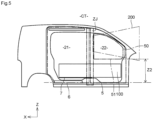
- FIG.4 represents the transport configuration CT of the partitioning device 3 according to which the movable partition wall 30 is oriented along an axis Y transverse to the vehicle.
- the upper part 31 is arranged identically to the separation configuration CS.
- the lower part 32 is pivoted about a transverse axis Y around the upper part 31.
- the lower part 32 is rotatably connected to the upper part 31, in particular by means of a second articulation device 42, which could be of the articulation hinge type, such that the partitioning device 3 delimits with the floor 7 an access opening between the loading area 21 and the passenger compartment area 22, on the passenger side.
- the height of the access opening is substantially equal to the height of the lower part 32.
- the second articulation device 42 is arranged at the interface of the upper and lower parts 31, 32, in particular their respective lower and upper edges.
- the second articulation device 42 is positioned at the level of the movable partition wall 30 at a height Z1 of the floor 7 which is defined relative to the field of vision and/or rear vision 200 of the driver.
- the locking device 60 which makes it possible to maintain the movable partition wall in the CS separation configuration, can also be used to keep the lower part 32 folded against the upper part 31.
- the height Z1 corresponds approximately to the height of the lower part 32 of the movable partition wall 30.
- the lower part 32 can be likened to an access hatch providing communication between the loading area 21 and the passenger compartment 22.
- the height Z1 is subject to the geometry of the front door 5, more particularly of the window frame 50 which constitutes it.
- the window frame 50 delimits a window threshold 51 which extends substantially horizontally at a height Z2 relative to the floor 7.
- the axis of rotation Y of the second articulation device 42 of the lower part 32 relative to the upper part 31 is at most located at the height Z2 defined by the window frame 50 of the front door 5.
- the height of the lower part 32 of the movable partition 30 is at most equal to the height Z2 along which the window sill 51 moves.
- the access opening between the loading 21 and passenger compartment 22 zones, as obtained by the pivoting of the lower part 32 against the upper part 31, is delimited in the upper part by the relative position of the second articulation device 42 with respect to the floor 7.
- the partitioning device in the CT transport configuration is thus composed of an architecture according to which the lower part 32 is folded over the upper part 31 in order to form an assembly whose thickness is less than a junction zone ZJ of the lateral openings 5 and 6, as can be seen in [ Fig.5 ].
- the outer lateral edges of the upper 31 and lower 32 parts of the movable partition are arranged transversely in line with the structure of the closed front 5 and rear 6 doors so that no part of the partitioning device 3 is inscribed in the driver's field of vision and/or rear vision 200.
- the field of vision and/or rear vision 200 is thus left approximately free at 180° relative to a vertical axis Z.
- the partitioning device 3 may be made of plastic or composite material, in particular with reinforced fiber. It may include hollow section beams in order to increase its impact resistance.
- the partitioning device 3 is made from a stamped steel plate in order to create horizontal stiffening elements.
- the partitioning device 3 of the invention is of simple design and inexpensive. It makes it possible to combine safety and loading capacity. increased by allowing the transport of at least one object placed at the loading areas 21 and passenger compartment 22, without the field of vision and/or rear vision 200 being obstructed, even partially.
- the partitioning device 3 is further remarkable in that the first articulation device 41 allows it to tilt completely into the passenger compartment area so that loading is greatly facilitated, in particular for a vehicle without a B-pillar whose lateral opening is a single opening which is intended to be closed by two directly adjacent openings 5, 6.
- the first and second articulation devices 41 and 42 are connected to position sensors 61, 62 electrically connected to a control unit 63 so that it is made possible to identify the actual configuration of the partitioning device 3, among the separation configuration CS, the loading configuration CC and the transport configuration CT.
- the control unit 63 is connected to a warning device 64, which can be visual and/or audible, so that the loading configuration CC generates a warning signal to the driver as soon as the engine computer 65 is woken up, for example when the driver presses a button for starting the vehicle.
- the arrangement 1 of the vehicle body 2 comprising a partitioning device 3 is remarkable in that it responds favorably to the safety aspect of transporting an object between the loading 21 and passenger compartment 22 zones, while making improved loading suitable for a vehicle without a center pillar.
Landscapes
- Engineering & Computer Science (AREA)
- Mechanical Engineering (AREA)
- Body Structure For Vehicles (AREA)
Applications Claiming Priority (1)
| Application Number | Priority Date | Filing Date | Title |
|---|---|---|---|
| FR2309735A FR3153056A1 (fr) | 2023-09-15 | 2023-09-15 | Dispositif de cloisonnement comportant les moyens rendant apte trois configurations d’utilisation. |
Publications (1)
| Publication Number | Publication Date |
|---|---|
| EP4523968A1 true EP4523968A1 (de) | 2025-03-19 |
Family
ID=89977386
Family Applications (1)
| Application Number | Title | Priority Date | Filing Date |
|---|---|---|---|
| EP24199873.1A Pending EP4523968A1 (de) | 2023-09-15 | 2024-09-11 | Trennwandvorrichtung mit mitteln zur ermöglichung von drei verwendungskonfigurationen |
Country Status (2)
| Country | Link |
|---|---|
| EP (1) | EP4523968A1 (de) |
| FR (1) | FR3153056A1 (de) |
Citations (3)
| Publication number | Priority date | Publication date | Assignee | Title |
|---|---|---|---|---|
| WO2014049233A1 (fr) * | 2012-09-25 | 2014-04-03 | Peugeot Citroen Automobiles Sa | Dispositif de cloisonnement pour vehicule utilitaire et vehicule presentant un tel dispositif |
| FR3010021A1 (fr) * | 2013-08-30 | 2015-03-06 | Peugeot Citroen Automobiles Sa | Dispositif de cloisonnement modulable a l'interieur d'un vehicule dote d'un moyen de cloisonnement amovible pour le stockage des objets allonges. |
| EP3715185A1 (de) * | 2019-03-25 | 2020-09-30 | Renault S.A.S. | Trennvorrichtung für ein kraftfahrzeug |
-
2023
- 2023-09-15 FR FR2309735A patent/FR3153056A1/fr active Pending
-
2024
- 2024-09-11 EP EP24199873.1A patent/EP4523968A1/de active Pending
Patent Citations (3)
| Publication number | Priority date | Publication date | Assignee | Title |
|---|---|---|---|---|
| WO2014049233A1 (fr) * | 2012-09-25 | 2014-04-03 | Peugeot Citroen Automobiles Sa | Dispositif de cloisonnement pour vehicule utilitaire et vehicule presentant un tel dispositif |
| FR3010021A1 (fr) * | 2013-08-30 | 2015-03-06 | Peugeot Citroen Automobiles Sa | Dispositif de cloisonnement modulable a l'interieur d'un vehicule dote d'un moyen de cloisonnement amovible pour le stockage des objets allonges. |
| EP3715185A1 (de) * | 2019-03-25 | 2020-09-30 | Renault S.A.S. | Trennvorrichtung für ein kraftfahrzeug |
Also Published As
| Publication number | Publication date |
|---|---|
| FR3153056A1 (fr) | 2025-03-21 |
Similar Documents
| Publication | Publication Date | Title |
|---|---|---|
| FR3051416B1 (fr) | Dispositif de separation entre un habitacle et un espace de chargement et vehicule equipe d'un tel dispositif | |
| EP2726309B1 (de) | Seitenschutzvorrichtung für ein kraftfahrzeug und entsprechendes kraftfahrzeug | |
| EP1706284B1 (de) | Schliessvorrichtung für ein mit einer luke und einem sonnendach versehenes fahrzeug | |
| EP3678879B1 (de) | Mechanismus für einen kraftfahrzeugkofferraum mit zwei öffnungspaneelen | |
| EP4523968A1 (de) | Trennwandvorrichtung mit mitteln zur ermöglichung von drei verwendungskonfigurationen | |
| EP1234702A1 (de) | Kombi-Kraftfahrzeug mit einem variablen Dach/Heckbereich | |
| EP1350672B1 (de) | Modulare Trennwand für den Innenraum, insbesondere eines Kraftfahrzeuges | |
| EP3539807A1 (de) | Optimierte heckklappenpfosten | |
| FR3051760A1 (fr) | Structure de pied milieu pourvu d'un element de renfort | |
| EP1193089B1 (de) | Seitentür für ein Kraftfahrzeug in zwei Teilen | |
| EP1234756A1 (de) | Kraftfahrzeug vom Kombi-umwandelbarem Typ | |
| FR2695596A1 (fr) | Dispositif d'obturation d'ouverture, notamment dispositif de toit ouvrant, pour véhicule. | |
| EP3524476A1 (de) | Abschirmungsvorrichtung für fahrzeug | |
| FR2859137A1 (fr) | Agencement d'un element de rigidification de deux portes a ouverture antagoniste | |
| WO2005080107A1 (fr) | Vehicule a toit decouvrable et hayon arriere | |
| FR3059609B1 (fr) | Dispositif d'articulation d'une porte laterale de vehicule | |
| FR2966779A1 (fr) | Dispositif de protection laterale pour un vehicule | |
| FR3163905A1 (fr) | .caisse de vehicule automobile de type fourgon. | |
| FR2677312A1 (fr) | Procede et dispositif de rangement d'objets longiformes a l'interieur d'un vehicule. | |
| FR3154947A1 (fr) | Dispositif d’accès pour un véhicule automobile avec des portes antagonistes. | |
| FR3162186A1 (fr) | Véhicule pourvu d’un dispositif amélioré de fixation d’un enrouleur arrière de ceinture de sécurité a la caisse du véhicule | |
| FR3148937A1 (fr) | Ensemble de vitres latérales pour véhicule automobile | |
| EP1806255B1 (de) | Befestigungseinheit eines Kofferraumdeckels für ein Kraftfahrzeug, und Kraftfahrzeug mit solch einer Befestigungseinheit | |
| WO2025026675A1 (fr) | Dispositif d'accès pour un véhicule automobile avec des portes antagonistes. | |
| FR2996500A1 (fr) | Carrosserie de vehicule avec pavillon arriere de toit coulissant. |
Legal Events
| Date | Code | Title | Description |
|---|---|---|---|
| PUAI | Public reference made under article 153(3) epc to a published international application that has entered the european phase |
Free format text: ORIGINAL CODE: 0009012 |
|
| STAA | Information on the status of an ep patent application or granted ep patent |
Free format text: STATUS: THE APPLICATION HAS BEEN PUBLISHED |
|
| AK | Designated contracting states |
Kind code of ref document: A1 Designated state(s): AL AT BE BG CH CY CZ DE DK EE ES FI FR GB GR HR HU IE IS IT LI LT LU LV MC ME MK MT NL NO PL PT RO RS SE SI SK SM TR |
|
| STAA | Information on the status of an ep patent application or granted ep patent |
Free format text: STATUS: REQUEST FOR EXAMINATION WAS MADE |
|
| 17P | Request for examination filed |
Effective date: 20250729 |
|
| GRAP | Despatch of communication of intention to grant a patent |
Free format text: ORIGINAL CODE: EPIDOSNIGR1 |
|
| STAA | Information on the status of an ep patent application or granted ep patent |
Free format text: STATUS: GRANT OF PATENT IS INTENDED |
|
| INTG | Intention to grant announced |
Effective date: 20250918 |
|
| GRAJ | Information related to disapproval of communication of intention to grant by the applicant or resumption of examination proceedings by the epo deleted |
Free format text: ORIGINAL CODE: EPIDOSDIGR1 |
|
| STAA | Information on the status of an ep patent application or granted ep patent |
Free format text: STATUS: REQUEST FOR EXAMINATION WAS MADE |
|
| INTC | Intention to grant announced (deleted) | ||
| GRAP | Despatch of communication of intention to grant a patent |
Free format text: ORIGINAL CODE: EPIDOSNIGR1 |
|
| STAA | Information on the status of an ep patent application or granted ep patent |
Free format text: STATUS: GRANT OF PATENT IS INTENDED |
|
| INTG | Intention to grant announced |
Effective date: 20260217 |