EP4524091A2 - Robotisches wartungssystem - Google Patents
Robotisches wartungssystem Download PDFInfo
- Publication number
- EP4524091A2 EP4524091A2 EP25150557.4A EP25150557A EP4524091A2 EP 4524091 A2 EP4524091 A2 EP 4524091A2 EP 25150557 A EP25150557 A EP 25150557A EP 4524091 A2 EP4524091 A2 EP 4524091A2
- Authority
- EP
- European Patent Office
- Prior art keywords
- vehicle
- robotic
- oil
- quick connect
- service operation
- Prior art date
- Legal status (The legal status is an assumption and is not a legal conclusion. Google has not performed a legal analysis and makes no representation as to the accuracy of the status listed.)
- Pending
Links
Images






Classifications
-
- B—PERFORMING OPERATIONS; TRANSPORTING
- B67—OPENING, CLOSING OR CLEANING BOTTLES, JARS OR SIMILAR CONTAINERS; LIQUID HANDLING
- B67D—DISPENSING, DELIVERING OR TRANSFERRING LIQUIDS, NOT OTHERWISE PROVIDED FOR
- B67D7/00—Apparatus or devices for transferring liquids from bulk storage containers or reservoirs into vehicles or into portable containers, e.g. for retail sale purposes
- B67D7/04—Apparatus or devices for transferring liquids from bulk storage containers or reservoirs into vehicles or into portable containers, e.g. for retail sale purposes for transferring fuels, lubricants or mixed fuels and lubricants
- B67D7/0401—Apparatus or devices for transferring liquids from bulk storage containers or reservoirs into vehicles or into portable containers, e.g. for retail sale purposes for transferring fuels, lubricants or mixed fuels and lubricants arrangements for automatically fuelling vehicles, i.e. without human intervention
-
- B—PERFORMING OPERATIONS; TRANSPORTING
- B25—HAND TOOLS; PORTABLE POWER-DRIVEN TOOLS; MANIPULATORS
- B25J—MANIPULATORS; CHAMBERS PROVIDED WITH MANIPULATION DEVICES
- B25J11/00—Manipulators not otherwise provided for
-
- B—PERFORMING OPERATIONS; TRANSPORTING
- B25—HAND TOOLS; PORTABLE POWER-DRIVEN TOOLS; MANIPULATORS
- B25J—MANIPULATORS; CHAMBERS PROVIDED WITH MANIPULATION DEVICES
- B25J11/00—Manipulators not otherwise provided for
- B25J11/008—Manipulators for service tasks
-
- B—PERFORMING OPERATIONS; TRANSPORTING
- B25—HAND TOOLS; PORTABLE POWER-DRIVEN TOOLS; MANIPULATORS
- B25J—MANIPULATORS; CHAMBERS PROVIDED WITH MANIPULATION DEVICES
- B25J11/00—Manipulators not otherwise provided for
- B25J11/008—Manipulators for service tasks
- B25J11/0085—Cleaning
-
- B—PERFORMING OPERATIONS; TRANSPORTING
- B25—HAND TOOLS; PORTABLE POWER-DRIVEN TOOLS; MANIPULATORS
- B25J—MANIPULATORS; CHAMBERS PROVIDED WITH MANIPULATION DEVICES
- B25J19/00—Accessories fitted to manipulators, e.g. for monitoring, for viewing; Safety devices combined with or specially adapted for use in connection with manipulators
- B25J19/02—Sensing devices
- B25J19/021—Optical sensing devices
- B25J19/023—Optical sensing devices including video camera means
-
- B—PERFORMING OPERATIONS; TRANSPORTING
- B60—VEHICLES IN GENERAL
- B60S—SERVICING, CLEANING, REPAIRING, SUPPORTING, LIFTING, OR MANOEUVRING OF VEHICLES, NOT OTHERWISE PROVIDED FOR
- B60S5/00—Servicing, maintaining, repairing, or refitting of vehicles
-
- B—PERFORMING OPERATIONS; TRANSPORTING
- B67—OPENING, CLOSING OR CLEANING BOTTLES, JARS OR SIMILAR CONTAINERS; LIQUID HANDLING
- B67D—DISPENSING, DELIVERING OR TRANSFERRING LIQUIDS, NOT OTHERWISE PROVIDED FOR
- B67D7/00—Apparatus or devices for transferring liquids from bulk storage containers or reservoirs into vehicles or into portable containers, e.g. for retail sale purposes
- B67D7/06—Details or accessories
- B67D7/36—Arrangements of flow- or pressure-control valves
-
- F—MECHANICAL ENGINEERING; LIGHTING; HEATING; WEAPONS; BLASTING
- F01—MACHINES OR ENGINES IN GENERAL; ENGINE PLANTS IN GENERAL; STEAM ENGINES
- F01M—LUBRICATING OF MACHINES OR ENGINES IN GENERAL; LUBRICATING INTERNAL COMBUSTION ENGINES; CRANKCASE VENTILATING
- F01M11/00—Component parts, details or accessories, not provided for in, or of interest apart from, groups F01M1/00 - F01M9/00
- F01M11/04—Filling or draining lubricant of or from machines or engines
- F01M11/0458—Lubricant filling and draining
-
- B—PERFORMING OPERATIONS; TRANSPORTING
- B67—OPENING, CLOSING OR CLEANING BOTTLES, JARS OR SIMILAR CONTAINERS; LIQUID HANDLING
- B67D—DISPENSING, DELIVERING OR TRANSFERRING LIQUIDS, NOT OTHERWISE PROVIDED FOR
- B67D7/00—Apparatus or devices for transferring liquids from bulk storage containers or reservoirs into vehicles or into portable containers, e.g. for retail sale purposes
- B67D7/04—Apparatus or devices for transferring liquids from bulk storage containers or reservoirs into vehicles or into portable containers, e.g. for retail sale purposes for transferring fuels, lubricants or mixed fuels and lubricants
- B67D7/0401—Apparatus or devices for transferring liquids from bulk storage containers or reservoirs into vehicles or into portable containers, e.g. for retail sale purposes for transferring fuels, lubricants or mixed fuels and lubricants arrangements for automatically fuelling vehicles, i.e. without human intervention
- B67D2007/0403—Fuelling robots
- B67D2007/0417—Manipulator arms
-
- B—PERFORMING OPERATIONS; TRANSPORTING
- B67—OPENING, CLOSING OR CLEANING BOTTLES, JARS OR SIMILAR CONTAINERS; LIQUID HANDLING
- B67D—DISPENSING, DELIVERING OR TRANSFERRING LIQUIDS, NOT OTHERWISE PROVIDED FOR
- B67D7/00—Apparatus or devices for transferring liquids from bulk storage containers or reservoirs into vehicles or into portable containers, e.g. for retail sale purposes
- B67D7/04—Apparatus or devices for transferring liquids from bulk storage containers or reservoirs into vehicles or into portable containers, e.g. for retail sale purposes for transferring fuels, lubricants or mixed fuels and lubricants
- B67D7/0401—Apparatus or devices for transferring liquids from bulk storage containers or reservoirs into vehicles or into portable containers, e.g. for retail sale purposes for transferring fuels, lubricants or mixed fuels and lubricants arrangements for automatically fuelling vehicles, i.e. without human intervention
- B67D2007/0444—Sensors
- B67D2007/0455—Sensors recognising the position
- B67D2007/0457—Sensors recognising the position of the car
- B67D2007/0463—Sensors recognising the position of the car optically
-
- B—PERFORMING OPERATIONS; TRANSPORTING
- B67—OPENING, CLOSING OR CLEANING BOTTLES, JARS OR SIMILAR CONTAINERS; LIQUID HANDLING
- B67D—DISPENSING, DELIVERING OR TRANSFERRING LIQUIDS, NOT OTHERWISE PROVIDED FOR
- B67D7/00—Apparatus or devices for transferring liquids from bulk storage containers or reservoirs into vehicles or into portable containers, e.g. for retail sale purposes
- B67D7/04—Apparatus or devices for transferring liquids from bulk storage containers or reservoirs into vehicles or into portable containers, e.g. for retail sale purposes for transferring fuels, lubricants or mixed fuels and lubricants
- B67D7/0401—Apparatus or devices for transferring liquids from bulk storage containers or reservoirs into vehicles or into portable containers, e.g. for retail sale purposes for transferring fuels, lubricants or mixed fuels and lubricants arrangements for automatically fuelling vehicles, i.e. without human intervention
- B67D2007/0444—Sensors
- B67D2007/0455—Sensors recognising the position
- B67D2007/0474—Sensors recognising the position of the filling nozzle relative to the fuel tank opening, e.g. engagement between nozzle and tank opening
-
- B—PERFORMING OPERATIONS; TRANSPORTING
- B67—OPENING, CLOSING OR CLEANING BOTTLES, JARS OR SIMILAR CONTAINERS; LIQUID HANDLING
- B67D—DISPENSING, DELIVERING OR TRANSFERRING LIQUIDS, NOT OTHERWISE PROVIDED FOR
- B67D7/00—Apparatus or devices for transferring liquids from bulk storage containers or reservoirs into vehicles or into portable containers, e.g. for retail sale purposes
- B67D7/06—Details or accessories
- B67D7/08—Arrangements of devices for controlling, indicating, metering or registering quantity or price of liquid transferred
- B67D7/14—Arrangements of devices for controlling, indicating, metering or registering quantity or price of liquid transferred responsive to input of recorded programmed information, e.g. on punched cards
- B67D7/145—Arrangements of devices for controlling, indicating, metering or registering quantity or price of liquid transferred responsive to input of recorded programmed information, e.g. on punched cards by wireless communication means, e.g. RF, transponders or the like
-
- B—PERFORMING OPERATIONS; TRANSPORTING
- B67—OPENING, CLOSING OR CLEANING BOTTLES, JARS OR SIMILAR CONTAINERS; LIQUID HANDLING
- B67D—DISPENSING, DELIVERING OR TRANSFERRING LIQUIDS, NOT OTHERWISE PROVIDED FOR
- B67D7/00—Apparatus or devices for transferring liquids from bulk storage containers or reservoirs into vehicles or into portable containers, e.g. for retail sale purposes
- B67D7/06—Details or accessories
- B67D7/58—Arrangements of pumps
- B67D7/62—Arrangements of pumps power operated
Definitions
- Changing the motor oil in a motorized vehicle generally involves draining the "old” motor oil, replacing the “old” oil filter with a “new” oil filter, and adding “new” motor oil to the engine.
- the drain plug located under the oil pan at the bottom of the engine is unscrewed and the force of gravity is relied on to have the "old” motor oil drain out of the vehicle.
- the drain plug is reinstalled, either with the existing drain plug gasket or with a new drain plug gasket.
- the "old” oil filter is then unscrewed and replaced with a “new” oil filter.
- the drain plug reinstalled and the "new” oil filter installed the "new” oil is added to the engine, typically through an opening positioned at the top side of the engine.
- a human may utilize a jack to raise the vehicle off of the ground to provide sufficient access to the underside of the vehicle.
- the human may drive the vehicle up on ramps to provide sufficient access to the underside of the vehicle.
- the human may position the vehicle on a lift which when actuated raises the vehicle off of the ground to provide sufficient access to the underside of the vehicle.
- the human typically utilizes a socket wrench to unscrew the drain plug, and relies on a container placed under the vehicle to catch the drained oil. Once the oil is drained from the vehicle, the human may thereafter add a new gasket to the drain plug and utilize the socket wrench to reinstall the drain plug.
- the human may thereafter utilize a filter wrench or similar tool to remove the "old” oil filter and install a "new” oil filter.
- the vehicle is ready for the "new” oil to be added.
- the human prior to adding the new oil, the human generally opens the "hood” of the vehicle to gain access to the top side of the engine, unscrews the oil filler cap and places a funnel in the opening previously covered by the oil filler cap. The human may then open the "new oil” container and pour the new oil into the funnel, where the oil then flows into the engine of the vehicle. Once the desired amount of oil has been added, the human typically reinstalls the oil filler cap and closes the hood of the vehicle.
- the human in addition to the amount of human interaction utilized to complete the oil change, the human also carries the burden of securing the correct size drain plug gasket, the correct size oil filter and the recommended "new" oil (e.g., synthetic or non-synthetic, viscosity, etc.).
- the recommended "new" oil e.g., synthetic or non-synthetic, viscosity, etc.
- FIG. 1 illustrates a robotic servicing system 10, in accordance with at least one aspect of the present disclosure.
- the robotic servicing system 10 includes a robotic assembly 11, a user interface 12, one or more sensors 14, one or more indicating lights 16, an evacuation system 18, a refill system 20 and a control circuit 22.
- the robotic servicing system 10 may also include a purge system 24 and a filter cleansing system 26.
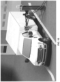
- the robotic servicing system 10 can be a stand-alone, unmanned station which performs a robotically implemented engine oil change in remote locations or at designated service providers.
- RFID radio-frequency identification
- the robotic servicing system 10 can also perform other various service operations on the vehicle such as, for example, refueling the vehicle, checking/altering tire pressure, checking brakes, greasing the vehicle and checking/adding various fluids (e.g., transmission fluid, wiper fluid, coolant, etc.) to the vehicle.
- various fluids e.g., transmission fluid, wiper fluid, coolant, etc.
- the robotic servicing system 10 will be described hereinafter in the context of an oil change service. However, it will be appreciated that the robotic servicing system 10 may be utilized to perform any number of different service operations on the vehicle.
- the user interface 12 includes a display 30, a keypad 32, an optical scanner 34, a card reader 36, and a printer 38.
- the display 30 provides information, such as for example, the make and model of the vehicle, the type of oil (synthetic or non-synthetic) to be used, the viscosity of the oil to be used, the cost for the oil change service, etc.
- the keypad 32 allows for the user to provide input data to the robotic servicing system 10 such as, for example, an upgrade to a synthetic oil, a request for a printed receipt, etc.
- the optical scanner 34 is configured to read a card such as, for example, a membership card or a rewards card associated with the vehicle or the operator of the vehicle.
- the card reader 36 is configured to read a credit card, a debit card, a gift card and the like in order to secure payment for the oil change service to be provided.
- the printer 38 is configured to print a receipt and/or other information for the user/operator of the vehicle.
- the "waste oil” container 42 is configured to receive the "waste oil” being evacuated from the vehicle and the valve 44 may be utilized to stop the flow of the "waste oil” being evacuated from the vehicle.
- the hosing 40 may be coupled to any number of "waste oil” containers 42 via any number of valves 44 and pumps 46.
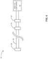
- the hosing 40 can be wound on a hose reel (not shown) and has a quick fit connector 48 coupled to an end of the hosing 40.
- the quick fit connector 48 is configured to mate with the quick fit valve of the vehicle.
- a sensor e.g., one of the sensors 14 of the robotic servicing system 10 is configured to sense whether a connection has been made between the quick fit connector 48 and the quick fit valve of the vehicle.
- the "new oil” container 52 contains the “new oil” utilized to refill the motor oil of the vehicle and the valve 44 may be utilized to stop the flow of the "new oil” being provided to the vehicle.
- the hosing 50 may be coupled to any number of "new oil” containers 52 via any number of valves 54 and pumps 56.
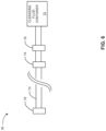
- the hosing 50 can be wound on a hose reel (not shown) and has a quick fit connector 58 coupled to an end of the hosing 50.
- the quick fit connector 58 is configured to mate with the quick fit valve of the vehicle.
- a sensor e.g., one of the sensors 14
- the robotic servicing system 10 is configured to sense whether a connection has been made between the quick fit connector 58 and the quick fit valve of the vehicle.
- the purging agent container 62 contains a pressurized purging agent (e.g., air or nitrogen) and the valve 64 may be utilized to stop the flow of the purging agent provided to the vehicle.
- the hosing 60 can be wound on a hose reel (not shown) and has a quick fit connector 68 coupled to an end of the hosing 60.
- the quick fit connector 68 is configured to mate with the quick fit valve of the vehicle.
- a sensor e.g., one of the sensors 14
- the robotic servicing system 10 is configured to sense whether a connection has been made between the quick fit connector 68 and the quick fit valve of the vehicle.
- the filter cleansing system 26 includes hosing 70 which is coupled to a cleansing fluid container 72 via a valve 74 and a pump 76.
- the cleansing fluid container 72 contains a cleansing fluid and the valve 74 may be utilized to stop the flow of the cleansing fluid provided to the vehicle.
- the hosing 70 can be wound on a hose reel (not shown) and has a quick fit connector 78 coupled to an end of the hosing 70.
- the quick fit connector 78 is configured to mate with the quick fit valve of the vehicle.
- a sensor e.g., one of the sensors 14
- the robotic servicing system 10 is configured to sense whether a connection has been made between the quick fit connector 78 and the quick fit valve of the vehicle.
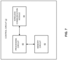
- the control circuit 22 is coupled to the robotic assembly 11, the user interface 12, the one or more sensors 14, the one or more indicating lights 16, the evacuation system 18, the refill system 20, the purge system 24 and the filter cleansing system 26 (See FIG. 1 ). As shown in FIG. 7 in accordance with at least one aspect of the present disclosure, the control circuit 22 includes a processing circuit 80, a memory circuit 82 and a wireless communication module 84.
- the processing circuit 80 may be, for example, hardwired circuitry, programmable circuitry (e.g., a computer processor including one or more individual instruction processing cores, processing unit, processor, microcontroller, microcontroller unit, controller, digital signal processor (DSP), programmable logic device (PLD), programmable logic array (PLA), or field programmable gate array (FPGA)), state machine circuitry, firmware that stores instructions executed by programmable circuitry, and any combination thereof.
- the processing circuit 70 may, collectively or individually, be embodied as circuitry that forms part of a larger system, for example, an integrated circuit (IC), an application-specific integrated circuit (ASIC), a system on-chip (SoC), desktop computers, laptop computers, tablet computers, servers, smart phones, etc.
- IC integrated circuit
- ASIC application-specific integrated circuit
- SoC system on-chip
- the processing circuit 80 may include, but is not limited to, electrical circuitry having at least one discrete electrical circuit, electrical circuitry having at least one integrated circuit, electrical circuitry having at least one application specific integrated circuit, electrical circuitry forming a general purpose computing device configured by a computer program (e.g., a general purpose computer configured by a computer program which at least partially carries out processes and/or devices described herein, or a microprocessor configured by a computer program which at least partially carries out processes and/or devices described herein), electrical circuitry forming a memory device (e.g., forms of random access memory), and/or electrical circuitry forming a communications device (e.g., a modem, communications switch, or optical-electrical equipment).
- a computer program e.g., a general purpose computer configured by a computer program which at least partially carries out processes and/or devices described herein, or a microprocessor configured by a computer program which at least partially carries out processes and/or devices described herein
- the memory circuit 82 is coupled to the processing circuit 80 and may include more than one type of memory.
- the memory 82 circuit may include volatile memory and non-volatile memory.
- the volatile memory can include random access memory (RAM), which can act as external cache memory.
- RAM random access memory
- the random access memory can be static random access memory (SRAM), dynamic random access memory (DRAM), synchronous dynamic random access memory (SDRAM), double data rate synchronous dynamic random access memory (DDR SDRAM), enhanced synchronous dynamic random access memory (ESDRAM), Synchlink dynamic random access memory (SLDRAM), direct Rambus random access memory (DRRAM) and the like.
- the non-volatile memory can include read-only memory (ROM), programmable read-only memory (PROM), electrically programmable read-only memory, electrically erasable programmable read-only memory (EEPROM), flash memory and the like.
- the memory circuit 82 can also include removable/non-removable, volatile/non-volatile storage media, such as for example disk storage.
- the disk storage can include, but is not limited to, devices like a magnetic disk drive, a floppy disk drive, a tape drive, a Jaz drive, a Zip drive, a LS-60 drive, a flash memory card, or a memory stick.
- the disk storage can include storage media separately or in combination with other storage media including, but not limited to, an optical disc drive such as a compact disc ROM device (CD-ROM), a compact disc recordable drive (CD-R Drive), a compact disc rewritable drive (CD-RW Drive), a digital versatile disc ROM drive (DVD-ROM) and the like.
- an optical disc drive such as a compact disc ROM device (CD-ROM), a compact disc recordable drive (CD-R Drive), a compact disc rewritable drive (CD-RW Drive), a digital versatile disc ROM drive (DVD-ROM) and the like.
- the wireless communication module 84 is configured to enable communication between the robotic servicing system 10 and other devices/systems, including the vehicle, via a network 132 (See FIG. 10 ), where the communications between the wireless communications module 84 and the network 132 are wireless communications.
- the vehicle may emit a wireless signal associated with a radio-frequency identification (RFID) tag of the vehicle and the control circuit 22 may be configured to utilize the signal to automatically identify the vehicle based on the signal.
- RFID radio-frequency identification
- the control circuit 22 may access a database of vehicles enrolled in member service rolls and match information in the signal (e.g., a vehicle ID) with a vehicle in the database.
- the database includes information regarding make, model, year and engine of the vehicle, as well as the type, viscosity and volume of oil for the vehicle.
- the control circuit 22 based on the information in the database, the control circuit 22 identifies the make, model, year and engine of the vehicle and determines the type, viscosity and volume of oil associated with the vehicle. Stated differently, the control circuit 22 determines the type, viscosity and volume of "new oil" to be added to the engine of the vehicle during a refill operation.
- the one or more controllers 96 are configured to control the operation of the motors 94 based on control signals (e.g., drive signals) output by the processing circuit 102.
- the vision system 98 is configured to assess the position of the robotic arm 90 and the tool 92 relative to the vehicle (or the target point of the vehicle such as, for example, a quick connect valve at an exterior of the vehicle, the drain plug of the vehicle, the oil filter of the vehicle, etc.) and provide this information as feedback to the processing circuit 102 so the processing circuit 102 can in turn determine the proper control signals to be output to the one or more controllers 94 to properly position the robotic arm 90 and the tool 92.
- the vision system 98 is configured to assess the position of the robotic arm 90 relative to any of the "unconnected" tools 92 and provide this information as feedback to the processing circuit 102 so the processing circuit 102 can in turn determine the proper control signals to be output to the one or more controllers 94 to properly position the robotic arm 90 relative to the "unconnected" tools 92 to autonomously connect the desired tool 92 to the robotic arm 90.
- the vision system 98 may be implemented in any suitable manner.
- the vision system 98 includes one or more cameras or other imaging devices.
- the vision system 98 is implemented by a laser vision system.
- the vision system is implemented by a machine vision system.
- the plurality of sensors 100 may be similar or identical to the sensors 14 described hereinabove. According to various aspects, one or more of the sensors 100 are configured to sense whether the robotic arm 90 has engaged with one of the tools 92, or whether a tool 92 engaged with the robotic arm 90 has engaged with any of the above-described quick fit connectors 48, 58, 68, 78 (or any of the hosing 40, 50, 60, 70). Similarly, one or more of the sensors 100 may be configured to sense whether any of the tools 92 have engaged with the drain plug of the vehicle, with the oil filter of the vehicle, etc.
- FIG. 9 illustrates a method 110 of performing a robotically controlled oil change service in accordance with at least one aspect of the present disclosure.
- the method 110 may be implemented by the robotic servicing system 10.
- the control circuit 22 or the robotic assembly 11 e.g., the vision system 98, the sensors 100 or the processing circuit 102 recognizes whether the vehicle has a service ID associated with vehicles enrolled in member service rolls.
- the recognition may be a result of a signal communicated from the vehicle (e.g., a signal associated with a radio-frequency identification (RFID) tag) or an image of the vehicle (or an image of a license plate, a bar code, or the like on the vehicle) captured by the vision system 98.
- RFID radio-frequency identification
- the control circuit 22 or the processing circuit 102 Upon receipt of the signal, the control circuit 22 or the processing circuit 102 operates to allow the purge aspect of the oil change service to begin. According to various aspects, without the signal, the control circuit 22 or the processing circuit 102 operates as if the connection has not been made and prevents the purge aspect of the oil change service from beginning. In other words, the control circuit 22 or the processing circuit 102 locks out the purge aspect of the oil change service until the signal is communicated from the sensor.
- the control circuit 22 or the processing circuit 102 Upon receipt of the signal, the control circuit 22 or the processing circuit 102 operates to allow the filter cleansing aspect of the oil change service to begin. According to various aspects, without the signal, the control circuit 22 or the processing circuit 102 operates as if the connection has not been made and prevents the filter cleansing aspect of the oil change service from beginning. In other words, the control circuit 22 or the processing circuit 102 locks out the filter cleansing aspect of the oil change service until the signal is communicated from the sensor.
- the robotic servicing system 10 is controlled to introduce the cleansing fluid from the filter cleaning container 72 to the quick fit valve of the vehicle, which is coupled to the reusable oil filter of the vehicle.
- a reusable filter can be found, for example, in U.S. Patent Application Publication No. 20190282935 , the entire content of which is hereby incorporated by reference.
- the cleansing fluid is introduced to the reusable filter in reverse flow - from a clean side of the filter to an unfiltered side.
- the cleansing fluid acts to back flush contaminants from the 'unfiltered' side of filter media.
- the control circuit 22 or the processing circuit 102 is configured to monitor the cleansing fluid used for the filter cleansing, and determine when contaminants in the cleansing fluid have reached a desired level. Once the desired level has been reached, the control circuit 22 or the processing circuit 102 may operate to stop the filter cleansing aspect of the oil change service.
- the robotic servicing system 10 may be controlled to initiate 120 the evacuation aspect of the oil change service by autonomously attaching the quick fit connector 48 coupled to an end of the hosing 40 of the evacuation system 18 to the quick fit valve of the vehicle.
- a sensor e.g., one of the sensors 14 or one of the sensors 100
- the connection between the quick fit connector 48 and the quick fit valve of the vehicle has been made, generate a signal indicative of the connection having been made, and communicate the signal to the control circuit 22 or the processing circuit 102.
- the robotic servicing system 10 "pulls" the oil from the engine sump to the quick fit valve of the vehicle, through the quick fit connector 48 and the hosing 40 of the evacuation system 18 and back to the "waste oil” container 42.
- the pressurized pulling (i.e., negative pressure) of the oil from the engine sump results in a more thorough and complete evacuation of the engine oil than is the case with traditional gravity draining.
- the robotic servicing system 10 can then be controlled to change 122 the oil filter (or oil filters) of the vehicle or initiate 124 the refill aspect of the oil change service.
- the robotic servicing system 10 may be controlled to change a conventional oil filter (as would almost always be the case) or a reusable oil filter if the reusable filter was not adequately cleaned by the purge aspect, the filter cleansing aspect and the cleansing fluid purge aspect of the oil change service.
- the robotic servicing system 10 may be controlled to initiate 124 the refill aspect of the oil change service by autonomously attaching the quick fit connector 58 coupled to an end of the hosing 50 of the refill system 20 to the quick fit valve of the vehicle.
- the robotic servicing system 10 "pushes" new clean motor oil from the "new oil” container 52 into the quick fit valve of the vehicle, where the new clean oil is then distributed to the engine of the vehicle via the oil filter (or oil filters).
- the control circuit 22 or the processing circuit 102 controls the delivery of the correct type, viscosity and volume of "new oil” to the engine of the vehicle.
- the Internet and/or World Wide Web may include elements, such as, for example, intermediate nodes, proxy servers, routers, switches, and adapters configured to direct and/or deliver data.
- the robotic servicing system 10 is configured to communicate with the one or more computing systems 134 via the network 132 using various communication protocols (e.g., HTTP, TCP/IP, UDP, WAP, WiFi, Bluetooth) and/or to operate within or in concert with one or more other communications systems.
- various communication protocols e.g., HTTP, TCP/IP, UDP, WAP, WiFi, Bluetooth
- IP address Internet Protocol address
- the one or more computing systems 134 can include, for example, a computing system of an owner of the robotic servicing system 10, a computing system of a service provider associated with the robotic servicing system 10, a computing system associated with an owner of the vehicle being serviced by the robotic servicing system 10, etc., and each of these computing systems can be at locations which are remote from the vehicle being serviced.
- Example 6 The robotic serving system of Examples 4 or 5, wherein the robotic assembly further comprises at least one motor coupled to the at least one robotic arm and at least one controller coupled to the at least one motor.
- Example 14 The robotic serving system of Examples 1, 2, 3, 4, 5, 6, 7, 8, 9, 10, 11, 12 or 13, further comprising a purge system couplable to the robotic assembly.
- Example 15 The robotic serving system of Example 14, further comprising a filter cleansing system couplable to the robotic assembly.
- Example 16 - A method of performing a robotically controlled oil change service comprises utilizing a robotic assembly to couple an evacuation system to a quick connect valve of a vehicle to evacuate oil from an engine of the vehicle, utilizing the robotic assembly to couple a refill system to the quick connect valve of the vehicle, and controlling a volume of new oil added to the vehicle via the refill system.
- Example 17 The method of Example 16, further comprising automatically identifying the vehicle based on at least one of the following (1) a signal communicated from the vehicle and (2) an image associated with the vehicle.
- Example 18 The method of Example 17, further comprising determining a type, a viscosity and a volume of the new oil based on the identified vehicle.
- Example 19 The method of Examples 16, 17 or 18, further comprising introducing a purging agent to an oil filter of the vehicle.
- Example 20 The method of Example 19, further comprising introducing a cleansing fluid to the oil filter of the vehicle.
- a robotic servicing system comprising:
- Statement 9 The robotic servicing system of Statement 8, wherein a first one of the one or more sensors is configured to sense whether the first quick connect fitting is connected to the quick connect valve of the vehicle.
- a method of performing a robotically controlled oil change service comprising:
- Statement 17 The method of Statement 16, further comprising automatically identifying the vehicle based on at least one of the following:
- Statement 18 The method of Statement 17, further comprising determining a type, a viscosity and a volume of the new oil based on the identified vehicle.
- Statement 19 The method of Statement 16, further comprising introducing a purging agent to an oil filter of the vehicle.
- Statement 20 The method of Statement 19, further comprising introducing a cleansing fluid to the oil filter of the vehicle.
- the robotic servicing system 10 may also be configure to provide analogous services for other types of machines such as, for example, earth moving machines (e.g., an excavator, a high-lift, a bulldozer, etc.), machines other than earth moving machines, mobile generators, etc.
- earth moving machines e.g., an excavator, a high-lift, a bulldozer, etc.
Landscapes
- Engineering & Computer Science (AREA)
- Mechanical Engineering (AREA)
- Robotics (AREA)
- Multimedia (AREA)
- General Engineering & Computer Science (AREA)
- Vehicle Cleaning, Maintenance, Repair, Refitting, And Outriggers (AREA)
- Manipulator (AREA)
Applications Claiming Priority (3)
| Application Number | Priority Date | Filing Date | Title |
|---|---|---|---|
| US201962880007P | 2019-07-29 | 2019-07-29 | |
| EP20846967.6A EP4003670B1 (de) | 2019-07-29 | 2020-07-29 | Roboter-gestütztes wartungssystem |
| PCT/US2020/043991 WO2021021878A1 (en) | 2019-07-29 | 2020-07-29 | Robotic servicing system |
Related Parent Applications (1)
| Application Number | Title | Priority Date | Filing Date |
|---|---|---|---|
| EP20846967.6A Division EP4003670B1 (de) | 2019-07-29 | 2020-07-29 | Roboter-gestütztes wartungssystem |
Publications (2)
| Publication Number | Publication Date |
|---|---|
| EP4524091A2 true EP4524091A2 (de) | 2025-03-19 |
| EP4524091A3 EP4524091A3 (de) | 2025-07-16 |
Family
ID=74230120
Family Applications (2)
| Application Number | Title | Priority Date | Filing Date |
|---|---|---|---|
| EP25150557.4A Pending EP4524091A3 (de) | 2019-07-29 | 2020-07-29 | Robotisches wartungssystem |
| EP20846967.6A Active EP4003670B1 (de) | 2019-07-29 | 2020-07-29 | Roboter-gestütztes wartungssystem |
Family Applications After (1)
| Application Number | Title | Priority Date | Filing Date |
|---|---|---|---|
| EP20846967.6A Active EP4003670B1 (de) | 2019-07-29 | 2020-07-29 | Roboter-gestütztes wartungssystem |
Country Status (3)
| Country | Link |
|---|---|
| US (3) | US11608261B2 (de) |
| EP (2) | EP4524091A3 (de) |
| WO (1) | WO2021021878A1 (de) |
Families Citing this family (1)
| Publication number | Priority date | Publication date | Assignee | Title |
|---|---|---|---|---|
| EP4524091A3 (de) | 2019-07-29 | 2025-07-16 | RPM Industries, LLC | Robotisches wartungssystem |
Citations (1)
| Publication number | Priority date | Publication date | Assignee | Title |
|---|---|---|---|---|
| US20190282935A1 (en) | 2018-03-19 | 2019-09-19 | RPM Industries, LLC | System including a reuseable oil filter |
Family Cites Families (29)
| Publication number | Priority date | Publication date | Assignee | Title |
|---|---|---|---|---|
| US3527268A (en) * | 1967-07-26 | 1970-09-08 | Standard Oil Co | Device for automatically filling vehicle tanks with motor fuel |
| US4708175A (en) * | 1986-08-25 | 1987-11-24 | Gmf Robotics Corporation | Method and apparatus for automated filling of a container with a fluid |
| US5318080A (en) * | 1991-10-23 | 1994-06-07 | Viken James P | Transmission fluid changer |
| US5626170A (en) * | 1993-02-01 | 1997-05-06 | Flo-Dynamics, Inc. | Automatic transmission fluid changer apparatus |
| US5462679A (en) * | 1993-09-16 | 1995-10-31 | Nelson Industries, Inc. | Apparatus and method for in situ cleaning of oil filter |
| US5787372A (en) * | 1994-04-25 | 1998-07-28 | Edwards; Robert W. | Automated fluid changing system with single-point connection |
| US5415247A (en) * | 1994-05-20 | 1995-05-16 | Knorr; Robert | Automotive fluid exchange system |
| US5554278A (en) * | 1994-06-03 | 1996-09-10 | Henderson; Bruce L. | Quick change oil recycler |
| US7150286B2 (en) * | 1997-10-30 | 2006-12-19 | Rpm Industries, Inc. | Methods and systems for performing, monitoring and analyzing multiple machine fluid processes |
| DE29908866U1 (de) * | 1999-05-21 | 2000-02-24 | California Kleindienst Holding GmbH, 86153 Augsburg | Fahrzeugbehandlungsanlage |
| DE19962969A1 (de) * | 1999-12-24 | 2001-07-12 | Bosch Gmbh Robert | Anordnung zur Einleitung von Betriebsflüssigkeit in eine Einfüllöffnung |
| US6463967B1 (en) | 2000-11-17 | 2002-10-15 | The Lubrizol Corporation | System for diagnosing, maintaining and reporting the performance and safety condition of apparatus during refueling |
| US20030164200A1 (en) * | 2001-03-16 | 2003-09-04 | American Controls, Inc. | Assembly line fluid filling system and method |
| US6595228B1 (en) * | 2001-11-27 | 2003-07-22 | Motorvac Technologies, Inc. | Vehicle fluid transfer system |
| US20050279385A1 (en) * | 2004-06-16 | 2005-12-22 | Ryko Manufacturing Company | Apparatus and method for positioning a vehicle in the wash area of a vehicle wash system |
| WO2007106486A1 (en) * | 2006-03-13 | 2007-09-20 | Colder Products Company | Connection state sensing for coupling device |
| RU2607912C2 (ru) * | 2007-03-09 | 2017-01-11 | Макдоналд Деттуилер энд Ассошиэйтс Инк. | Система и способ дозаправки спутников |
| US8393362B1 (en) * | 2010-01-30 | 2013-03-12 | James A. Hollerback | Automated vehicle fueling apparatus and method |
| US9260988B2 (en) * | 2013-09-12 | 2016-02-16 | Euroiltec Industry Co., Ltd. | Self-help oil changing apparatus |
| US10046962B2 (en) * | 2016-06-21 | 2018-08-14 | Hall Labs Llc | Mobile vehicle refueling system |
| US10514088B2 (en) * | 2016-10-21 | 2019-12-24 | Nio Usa, Inc. | Automatic oil exchange service for electric vehicle gearboxes |
| DE102016221213B4 (de) | 2016-10-27 | 2019-07-04 | Audi Ag | Automatisiertes Instandhaltungssystem |
| US10207411B2 (en) * | 2017-02-01 | 2019-02-19 | Toyota Research Institute, Inc. | Systems and methods for servicing a vehicle |
| US10095239B1 (en) * | 2017-03-31 | 2018-10-09 | Uber Technologies, Inc. | Autonomous vehicle paletization system |
| US10974546B2 (en) * | 2018-04-20 | 2021-04-13 | Robotire, Inc. | Automated removal and replacement of vehicle wheels and tires |
| US10759650B2 (en) * | 2018-09-07 | 2020-09-01 | Joseph F. LAWLER, III | Automated engine oil change system and method |
| CN109849860A (zh) | 2019-02-28 | 2019-06-07 | 深圳市元征科技股份有限公司 | 一种智能换油方法及装置 |
| US20200353900A1 (en) * | 2019-05-06 | 2020-11-12 | Osman Yusuf | Automated vehicle service network, method, and system |
| EP4524091A3 (de) | 2019-07-29 | 2025-07-16 | RPM Industries, LLC | Robotisches wartungssystem |
-
2020
- 2020-07-29 EP EP25150557.4A patent/EP4524091A3/de active Pending
- 2020-07-29 EP EP20846967.6A patent/EP4003670B1/de active Active
- 2020-07-29 WO PCT/US2020/043991 patent/WO2021021878A1/en not_active Ceased
- 2020-07-29 US US16/941,970 patent/US11608261B2/en active Active
-
2023
- 2023-01-30 US US18/161,275 patent/US12286339B2/en active Active
-
2025
- 2025-03-26 US US19/090,542 patent/US20250313450A1/en active Pending
Patent Citations (1)
| Publication number | Priority date | Publication date | Assignee | Title |
|---|---|---|---|---|
| US20190282935A1 (en) | 2018-03-19 | 2019-09-19 | RPM Industries, LLC | System including a reuseable oil filter |
Also Published As
| Publication number | Publication date |
|---|---|
| WO2021021878A1 (en) | 2021-02-04 |
| EP4003670B1 (de) | 2025-01-08 |
| US12286339B2 (en) | 2025-04-29 |
| US20250313450A1 (en) | 2025-10-09 |
| EP4003670A4 (de) | 2023-08-30 |
| US20230278853A1 (en) | 2023-09-07 |
| EP4003670C0 (de) | 2025-01-08 |
| US11608261B2 (en) | 2023-03-21 |
| EP4524091A3 (de) | 2025-07-16 |
| US20210032093A1 (en) | 2021-02-04 |
| EP4003670A1 (de) | 2022-06-01 |
Similar Documents
| Publication | Publication Date | Title |
|---|---|---|
| US20250059900A1 (en) | Autonomous oil change system | |
| US20250313450A1 (en) | Robotic servicing system | |
| EP3670276B1 (de) | Servicestation für eine autonome fahrzeugreinigung | |
| US20180087418A1 (en) | Fluid Method and System | |
| US20180258806A1 (en) | Fluid Method and System | |
| US20130048088A1 (en) | Fluid management system | |
| US20180266288A1 (en) | Fluid Method and System | |
| WO2018024336A1 (de) | System und verfahren zur fahrzeugpflege sowie verwendung eines derartigen systems | |
| WO2008079749A2 (en) | Manufactured product configuration | |
| CN113597545A (zh) | 用于车辆的便携式无线连接诊断系统 | |
| KR20170012291A (ko) | 유압 시스템에서의 파이프의 플러싱을 위한 방법 및 플러싱을 위한 플랜트 | |
| DE102013004112B4 (de) | Filter für Fluid und Verfahren zur Erkennung eines Filterelements in einem Filtergehäuse | |
| DE102016215523A1 (de) | Verfahren für eine Datenverarbeitungsanlage zur Erhaltung eines Betriebszustands eines Fahrzeugs | |
| DE102014101714A1 (de) | Multifunktionales Hydraulikaggregat | |
| EP2455613A2 (de) | Lufttrocknungskartusche | |
| DE102018222645A1 (de) | Verfahren zur autonomen Fahrzeugreinigung | |
| DE102005002245A1 (de) | Verfahren und Vorrichtung zum Betanken eines Fahrzeugs | |
| DE102016109015A1 (de) | Haushaltsgerät und Verfahren zum Überwachen eines Haushaltsgeräts | |
| WO2016050428A1 (de) | Prüfscheibensystem | |
| DE202006013601U1 (de) | Tankverschlussvorrichtung sowie Betankungssystem | |
| DE102019132834A1 (de) | Verfahren zum Durchführen einer fahrzeugbasierten Serviceleistung sowie ein Kraftfahrzeug hierzu | |
| EP2578529B1 (de) | Verfahren und Vorrichtung zum Fördern von Kraftstoff aus dem Kraftstofftank eines Kraftfahrzeugs | |
| DE102019000646A1 (de) | Windschutzscheibe für ein Fahrzeug | |
| DE102015212493A1 (de) | Verfahren und Vorrichtung zur Unterstützung des Abholvorganges von Einkaufsgütern | |
| EP4296217B1 (de) | Entnahmesystem und verfahren zum betrieb eines entnahmesystems |
Legal Events
| Date | Code | Title | Description |
|---|---|---|---|
| PUAI | Public reference made under article 153(3) epc to a published international application that has entered the european phase |
Free format text: ORIGINAL CODE: 0009012 |
|
| STAA | Information on the status of an ep patent application or granted ep patent |
Free format text: STATUS: THE APPLICATION HAS BEEN PUBLISHED |
|
| AC | Divisional application: reference to earlier application |
Ref document number: 4003670 Country of ref document: EP Kind code of ref document: P |
|
| AK | Designated contracting states |
Kind code of ref document: A2 Designated state(s): AL AT BE BG CH CY CZ DE DK EE ES FI FR GB GR HR HU IE IS IT LI LT LU LV MC MK MT NL NO PL PT RO RS SE SI SK SM TR |
|
| REG | Reference to a national code |
Ref country code: DE Ref legal event code: R079 Free format text: PREVIOUS MAIN CLASS: B67D0007620000 Ipc: B25J0011000000 |
|
| PUAL | Search report despatched |
Free format text: ORIGINAL CODE: 0009013 |
|
| AK | Designated contracting states |
Kind code of ref document: A3 Designated state(s): AL AT BE BG CH CY CZ DE DK EE ES FI FR GB GR HR HU IE IS IT LI LT LU LV MC MK MT NL NO PL PT RO RS SE SI SK SM TR |
|
| RIC1 | Information provided on ipc code assigned before grant |
Ipc: B25J 11/00 20060101AFI20250610BHEP Ipc: F01M 11/04 20060101ALI20250610BHEP Ipc: B67D 7/04 20100101ALI20250610BHEP Ipc: B67D 7/62 20100101ALI20250610BHEP Ipc: B67D 7/14 20100101ALI20250610BHEP Ipc: B67D 7/36 20100101ALI20250610BHEP |
|
| STAA | Information on the status of an ep patent application or granted ep patent |
Free format text: STATUS: REQUEST FOR EXAMINATION WAS MADE |
|
| 17P | Request for examination filed |
Effective date: 20260114 |