EP4524105A2 - Verfahren zur herstellung von lithiumsulfid - Google Patents
Verfahren zur herstellung von lithiumsulfid Download PDFInfo
- Publication number
- EP4524105A2 EP4524105A2 EP24200718.5A EP24200718A EP4524105A2 EP 4524105 A2 EP4524105 A2 EP 4524105A2 EP 24200718 A EP24200718 A EP 24200718A EP 4524105 A2 EP4524105 A2 EP 4524105A2
- Authority
- EP
- European Patent Office
- Prior art keywords
- reactor
- layer
- lithium
- solid sulfur
- lithium source
- Prior art date
- Legal status (The legal status is an assumption and is not a legal conclusion. Google has not performed a legal analysis and makes no representation as to the accuracy of the status listed.)
- Pending
Links
Images
Classifications
-
- C—CHEMISTRY; METALLURGY
- C01—INORGANIC CHEMISTRY
- C01B—NON-METALLIC ELEMENTS; COMPOUNDS THEREOF; METALLOIDS OR COMPOUNDS THEREOF NOT COVERED BY SUBCLASS C01C
- C01B17/00—Sulfur; Compounds thereof
- C01B17/22—Alkali metal sulfides or polysulfides
-
- B—PERFORMING OPERATIONS; TRANSPORTING
- B01—PHYSICAL OR CHEMICAL PROCESSES OR APPARATUS IN GENERAL
- B01J—CHEMICAL OR PHYSICAL PROCESSES, e.g. CATALYSIS OR COLLOID CHEMISTRY; THEIR RELEVANT APPARATUS
- B01J21/00—Catalysts comprising the elements, oxides, or hydroxides of magnesium, boron, aluminium, carbon, silicon, titanium, zirconium, or hafnium
- B01J21/02—Boron or aluminium; Oxides or hydroxides thereof
- B01J21/04—Alumina
-
- B—PERFORMING OPERATIONS; TRANSPORTING
- B01—PHYSICAL OR CHEMICAL PROCESSES OR APPARATUS IN GENERAL
- B01J—CHEMICAL OR PHYSICAL PROCESSES, e.g. CATALYSIS OR COLLOID CHEMISTRY; THEIR RELEVANT APPARATUS
- B01J23/00—Catalysts comprising metals or metal oxides or hydroxides, not provided for in group B01J21/00
- B01J23/70—Catalysts comprising metals or metal oxides or hydroxides, not provided for in group B01J21/00 of the iron group metals or copper
- B01J23/74—Iron group metals
- B01J23/75—Cobalt
-
- B—PERFORMING OPERATIONS; TRANSPORTING
- B01—PHYSICAL OR CHEMICAL PROCESSES OR APPARATUS IN GENERAL
- B01J—CHEMICAL OR PHYSICAL PROCESSES, e.g. CATALYSIS OR COLLOID CHEMISTRY; THEIR RELEVANT APPARATUS
- B01J23/00—Catalysts comprising metals or metal oxides or hydroxides, not provided for in group B01J21/00
- B01J23/70—Catalysts comprising metals or metal oxides or hydroxides, not provided for in group B01J21/00 of the iron group metals or copper
- B01J23/74—Iron group metals
- B01J23/755—Nickel
-
- B—PERFORMING OPERATIONS; TRANSPORTING
- B01—PHYSICAL OR CHEMICAL PROCESSES OR APPARATUS IN GENERAL
- B01J—CHEMICAL OR PHYSICAL PROCESSES, e.g. CATALYSIS OR COLLOID CHEMISTRY; THEIR RELEVANT APPARATUS
- B01J23/00—Catalysts comprising metals or metal oxides or hydroxides, not provided for in group B01J21/00
- B01J23/70—Catalysts comprising metals or metal oxides or hydroxides, not provided for in group B01J21/00 of the iron group metals or copper
- B01J23/76—Catalysts comprising metals or metal oxides or hydroxides, not provided for in group B01J21/00 of the iron group metals or copper combined with metals, oxides or hydroxides provided for in groups B01J23/02 - B01J23/36
- B01J23/84—Catalysts comprising metals or metal oxides or hydroxides, not provided for in group B01J21/00 of the iron group metals or copper combined with metals, oxides or hydroxides provided for in groups B01J23/02 - B01J23/36 with arsenic, antimony, bismuth, vanadium, niobium, tantalum, polonium, chromium, molybdenum, tungsten, manganese, technetium or rhenium
- B01J23/85—Chromium, molybdenum or tungsten
- B01J23/88—Molybdenum
- B01J23/883—Molybdenum and nickel
-
- H—ELECTRICITY
- H01—ELECTRIC ELEMENTS
- H01M—PROCESSES OR MEANS, e.g. BATTERIES, FOR THE DIRECT CONVERSION OF CHEMICAL ENERGY INTO ELECTRICAL ENERGY
- H01M10/00—Secondary cells; Manufacture thereof
- H01M10/54—Reclaiming serviceable parts of waste accumulators
-
- C—CHEMISTRY; METALLURGY
- C01—INORGANIC CHEMISTRY
- C01P—INDEXING SCHEME RELATING TO STRUCTURAL AND PHYSICAL ASPECTS OF SOLID INORGANIC COMPOUNDS
- C01P2006/00—Physical properties of inorganic compounds
- C01P2006/80—Compositional purity
-
- H—ELECTRICITY
- H01—ELECTRIC ELEMENTS
- H01M—PROCESSES OR MEANS, e.g. BATTERIES, FOR THE DIRECT CONVERSION OF CHEMICAL ENERGY INTO ELECTRICAL ENERGY
- H01M10/00—Secondary cells; Manufacture thereof
- H01M10/05—Accumulators with non-aqueous electrolyte
- H01M10/052—Li-accumulators
-
- Y—GENERAL TAGGING OF NEW TECHNOLOGICAL DEVELOPMENTS; GENERAL TAGGING OF CROSS-SECTIONAL TECHNOLOGIES SPANNING OVER SEVERAL SECTIONS OF THE IPC; TECHNICAL SUBJECTS COVERED BY FORMER USPC CROSS-REFERENCE ART COLLECTIONS [XRACs] AND DIGESTS
- Y02—TECHNOLOGIES OR APPLICATIONS FOR MITIGATION OR ADAPTATION AGAINST CLIMATE CHANGE
- Y02E—REDUCTION OF GREENHOUSE GAS [GHG] EMISSIONS, RELATED TO ENERGY GENERATION, TRANSMISSION OR DISTRIBUTION
- Y02E60/00—Enabling technologies; Technologies with a potential or indirect contribution to GHG emissions mitigation
- Y02E60/10—Energy storage using batteries
-
- Y—GENERAL TAGGING OF NEW TECHNOLOGICAL DEVELOPMENTS; GENERAL TAGGING OF CROSS-SECTIONAL TECHNOLOGIES SPANNING OVER SEVERAL SECTIONS OF THE IPC; TECHNICAL SUBJECTS COVERED BY FORMER USPC CROSS-REFERENCE ART COLLECTIONS [XRACs] AND DIGESTS
- Y02—TECHNOLOGIES OR APPLICATIONS FOR MITIGATION OR ADAPTATION AGAINST CLIMATE CHANGE
- Y02W—CLIMATE CHANGE MITIGATION TECHNOLOGIES RELATED TO WASTEWATER TREATMENT OR WASTE MANAGEMENT
- Y02W30/00—Technologies for solid waste management
- Y02W30/50—Reuse, recycling or recovery technologies
- Y02W30/84—Recycling of batteries or fuel cells
Definitions
- the embodiments of the present disclosure generally relate to a method of preparing lithium sulfide. More particularly, the embodiments of the present disclosure relate to a method of preparing a high-purity lithium sulfide.
- a secondary battery which can be charged and discharged repeatedly has been widely employed as a power source for mobile electronic devices such as camcorders, mobile phones, laptop computers, and the like, and also as a power source for electric automobiles, hybrid vehicles, and the like.
- Lithium secondary batteries among the various types of secondary batteries are being actively developed due to their high operational voltage, energy density per unit weight, charging rate, and compact dimension.
- the support may include alumina
- the active metal may include at least one of Ni, Mo, Co and W.
- a ratio of the total number of moles of lithium atoms included in the lithium source layer relative to the total number of moles of sulfur atoms included in the solid sulfur layer may be in a range from 1 to 3.
- the reaction gas may include hydrogen or a hydrogen-nitrogen mixture gas.
- a reaction temperature in the reactor may be in a range from 300°C to 500°C.
- a reactor may include a first reactor and a second reactor.
- the solid sulfur layer and the catalyst layer may be disposed in the above first reactor, and the lithium source layer may be disposed in the second reactor.
- the reaction gas may be supplied from the first reactor to the second reactor to sequentially contact the solid sulfur layer, the catalyst layer and the lithium source layer.
- the solid sulfur layer may be disposed in the first reactor, the catalyst layer may be disposed in the second reactor, and the lithium source layer may be disposed in the third reactor.
- the reaction gas may be supplied from the first reactor to the second reactor and the third reactor to sequentially contact the solid sulfur layer, the catalyst layer and the lithium source layer.
- a solid sulfur layer, a catalyst layer and a lithium source layer may be sequentially arranged in a reactor.
- a reactor system comprising a catalyst layer disposed between a solid sulfur layer and a lithium source layer may be provided.
- a reaction gas may be fed first into the solid sulfur layer to pass through the solid sulfur layer, then through the catalyst layer, and after exiting the catalyst layer to pass through the lithium source layer to produce lithium sulfide.
- the lithium sulfide may be separated. The the separated lithium sulfide may be collected.
- a solid sulfur layer, a catalyst layer and a lithium source layer may be sequentially disposed in one or more reactors, and a reaction gas may be injected in a single direction (an omni-direction) to sequentially contact the layers, thereby generate a high-purity lithium sulfide under mild conditions.
- Embodiments of the present disclosure provide a method for preparing lithium sulfide with high purity and high yield using solid sulfur, a catalyst and a lithium source
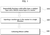
- FIG. 1 is a schematic process flow chart of a method of preparing lithium sulfide in accordance with embodiments of the present disclosure.
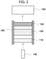
- FIG. 2 is a schematic process flow chart of a method of preparing lithium sulfide in accordance with embodiments of the present disclosure.
- a solid sulfur layer, a catalyst layer and a lithium source layer may be sequentially disposed inside a reactor (e.g., in an operation of S 10).
- reactor 100 may include a solid sulfur layer 110, a catalyst layer 120 and a lithium source layer 130.
- the reactor 100 may be operatively connected with a gas supplier 140 and a lithium sulfide collector 150.
- the solid sulfur layer 110, the catalyst layer 120 and the lithium source layer 130 may be sequentially disposed within the reactor 100 to fill the inside of the reactor 100.
- a reaction gas may sequentially pass through the solid sulfur, the catalyst and the lithium source layers 110, 120, and 130 according to the arranged order.
- a shape in which the solid sulfur layer 110, the catalyst layer 120 and the lithium source layer 130 are disposed is not particularly limited.
- the solid sulfur layer 110, the catalyst layer 120 and the lithium source layer 130 may be disposed in separated spaces.
- the solid sulfur layer 110, the catalyst layer 120 and the lithium source layer 130 may be disposed in a separated state by a separator in the same space.
- At least two layers of the solid sulfur layer 110, the catalyst layer 120 and the lithium source layer 130 may contact each other.
- the solid sulfur layer 110, the catalyst layer 120 and the lithium source layer 130 may be spaced apart from each other.
- a flow of the reaction gas may be promoted by increase of sequential contact with the layers, and lithium sulfide may be efficiently prepared, in an economic, environmentally optimal manner with high yield and purity.
- reaction gas is injected in both directions of the reactor 100 (e.g., from the solid sulfur layer to the lithium source layer and from the lithium source layer to the solid sulfur layer), a gas flow may not be substantially generated or a gas residence period may be increased to degrade the purity of the produced lithium sulfide.
- the other end portion may be connected to the reactor 100 or may be separated from the reactor.
- the other end may be connected to the reactor 100 through a pipe.
- the other end portion may be integral with the reactor 100.
- An eco-friendly and low-cost preparation process of lithium sulfide may be implemented using the solid sulfur produced as a by-product in the desulfurization process. Additionally, the solid sulfur may be easily controlled and sequentially disposed in the reactor, and generation of a hazardous gas may be decreased in the preparation process of lithium sulfide.
- the catalyst layer 120 may include a hydrogen-treated catalyst.
- the catalyst layer 120 may include at least one selected from a group consisting of Ni, Co, Fe, Mo, Cu, V and W as the active metal supported by the support.
- the catalyst may include at least one of Ni, Mo, Co and W as the active metal, so that the injected reaction gas may contact the catalyst layer 120 to promote a continuous flow. Accordingly, the reaction gas may contact and react with the lithium source.
- the lithium source may include at least one of lithium hydroxide and lithium oxide.
- Lithium hydroxide and lithium oxide may be present independently or in a mixed state in the lithium source layer 130.
- a lithium hydroxide powder and/or a lithium oxide powder may be used.
- An average particle diameter of the powder or the lithium oxide powder may be 2 mm or less.
- the waste cathode material may include a cathode current collector (e.g., aluminum (Al)) and a cathode active material layer, and the cathode active material layer may include a cathode active material, a conductive material and a binder.
- a cathode current collector e.g., aluminum (Al)
- the cathode active material layer may include a cathode active material, a conductive material and a binder.
- the conductive material may include, e.g., a carbon-based material such as graphite, carbon black, graphene, carbon nanotube, and the like.
- the binder may include a resin material such as vinylidene fluoride-hexafluoropropylene copolymer (PVDF-co-HFP), polyvinylidene fluoride (PVDF), polyacrylonitrile, polymethylmethacrylate, etc.
- the waste cathode material may be pulverized to form the waste cathode active material mixture.
- the waste cathode active material mixture may be heat-treated, and impurities contained in the cathode active material mixture may be removed or reduced. Accordingly, the purity of the preliminary precursor mixture may be improved, and thus, the purity of the recovered lithium precursor may also be improved.
- the reaction gas reacting with the waste cathode active material mixture may include a reductive gas.
- the preliminary precursor mixture may include, for example, lithium hydroxide, lithium oxide, a transition metal, a transition metal oxide, and the like.
- the lithium precursor may be recovered by washing the preliminary precursor mixture with water, and the lithium precursor may be separated from the transition metal by the washing treatment to be recovered in advance.
- the lithium precursor may include lithium hydroxide or a hydrate thereof.
- the recovered lithium precursor may be crystallized, for example, by a dry process.
- the reactor 100 may include a reactor capable of injecting the reaction gas in the desired single direction.
- the reactor 100 may include a tubular reactor, a top reactor, a stirring bath reactor, a fluidized bed reactor, and the like.
- the reaction gas injected into the reactor 100 may include hydrogen, and may further include an inert gas such as argon, nitrogen, helium, and the like.
- volume ratio of hydrogen contained in the reaction gas is less than 30%, a production time of lithium sulfide may be increased, thereby reducing efficiency.
- a reaction temperature by the injection of the reaction gas may be in a range from 300°C to 500°C. In some embodiments, the reaction temperature may be in a range from 300°C to 450°C.
- the reaction temperature is less than 300°C
- the reaction may not be activated or an activity may become low even though the reaction gas and solid sulfur contact each other to degrade yield of lithium sulfide. Further, purity of lithium sulfide may be lowered due to side reactions.
- reaction temperature exceeds 500°C
- a flow rate of the reaction gas may become non-uniform, and the prepared lithium sulfide may be excessively agglomerated to deteriorate the yield.
- an injection pressure of the reaction gas may be in a range from 0.1 bar to 5 bar.
- a reaction pressure may be similar to an atmospheric pressure or may be maintained to be higher than the atmospheric pressure depending on an amount of the injected reaction gas.
- the reaction pressure may be in a range from 0.5 bar to 4 bar, or from 1 bar to 3 bar. In the above range, purity of the prepared lithium sulfide may be further improved.
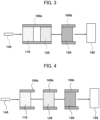
- FIGS. 3 and 4 are schematic process flow-charts for describing a method of preparing lithium sulfide in accordance with some embodiments of the present disclosure.
- the first reactor 100a may be connected to the gas supplier 140, and the second reactor 100b or the third reactor 100c may be connected to the lithium sulfide collector 150.
- the first reactor 100a, the second reactor 100b and the third reactor 100c may be connected to each other.
- a connecting method of the first reactor 100a, the second reactor 100b and the third reactor 100c is not particularly limited, and any connecting method capable of preventing leakage of the reaction gas, reactants, etc., and stably maintaining the reaction may be employed.
- the first reactor 100a, the second reactor 100b and the third reactor 100c may be connected to each other to transfer the reaction gas supplied to the first reactor 100a to the second reactor 100b and/or the third reactor 100c.
- the layers included in the first reactor 100a, the second reactor 100b and the third reactor 100c may be disposed in the same direction.
- the reaction gas may be supplied to the first reactor 100a in the single direction through the gas supplier 140.
- the reaction gas may be supplied in a direction toward the second reactor 100b or the third reactor 100c connected to the first reactor 100a and may form a unidirectional flow of the reaction gas from the first reactor 100a to the second reactor 100b or the third reactor 100c.
- the solid sulfur layer 110 and the catalyst layer 120 may be disposed in the first reactor 100a, and the lithium source layer 130 may be disposed in the second reactor 100b.
- the solid sulfur layer 110 and the catalyst layer 120 in the first reactor 100a may contact each other or may be spaced apart from each other.
- the solid sulfur layer 110 may be disposed in the first reactor 100a, and the catalyst layer 120 and the lithium source layer 130 may be disposed in the second reactor 100b.
- the catalyst layer 120 and the lithium source layer 130 in the second reactor 100b may contact or be spaced apart from each other.
- the reaction gas may be supplied to sequentially contact the solid sulfur layer 110, the catalyst layer 120 and the lithium source layer 130.
- the solid sulfur layer 110 may be disposed in the first reactor 100a, the catalyst layer 120 may be disposed in the second reactor 100b, and the lithium source layer 130 may be disposed in the third reactor 100c.
- lithium sulfide may be efficiently produced while suppressing impurities according to the unidirectional flow of reaction gas.
- the lithium sulfide obtained by the lithium sulfide collecting unit 150 may have high purity (e.g., 95% or more, 98% or more, or 99% or more) even when an additional purification is not further performed.
- the reaction gas may be injected in the single direction to pass through the catalyst layer 120 located between the solid sulfur layer 110 and the lithium source layer 130, so that the high purity lithium sulfide may be prepared even when the purification is omitted.
- a solvent may not be used in the arrangement of the solid sulfur layer 110, the catalyst layer 120 and the lithium source layer 130.
- the solid sulfur layer 110, the catalyst layer 120 and the lithium source layer 130 may not include a solvent.
- an organic solvent such as isopropyl alcohol, hexane, toluene, dimethylformamide, N-methylcaprolactam, N-methylpyrrolidone etc., may not be used. Accordingly, an additional residual solvent treatment may be omitted after the preparation of lithium sulfide, thus further enhancing the eco-friendly characteristics of the inventive process.
- a solid sulfur, a catalyst comprising an active metal on a support (active metal: NiMo/support: Al 2 O 3 ) and lithium hydroxide monohydrate (LiOH ⁇ H 2 O) were sequentially filled in a reactor.
- a hydrogen (100 vol%) gas was injected in a single direction into the reactor to sequentially contact the solid sulfur layer, the NiMo/Al 2 O 3 catalyst layer and the lithium hydroxide layer in the recited order. While injecting the hydrogen gas, the reaction was performed for 5 hours while maintaining a reaction pressure at 2 bar and a reaction temperature at 400°C. Thereafter, the reactor was moved to a Glove box, and a product located at a top of the reactor was separated to obtain lithium sulfide.
- the reaction was proceeded by the same method as that in Example 1, except that the reaction temperature was changed to 350°C.
- the reaction was proceeded by the same method as that in Example 1, except that the reaction temperature was changed to 300°C.
- the reaction was proceeded by the same method as that in Example 1, except that a mixed gas of hydrogen (50 vol%)/nitrogen (50 vol%) was used as the reaction gas.
Landscapes
- Chemical & Material Sciences (AREA)
- Organic Chemistry (AREA)
- Engineering & Computer Science (AREA)
- Chemical Kinetics & Catalysis (AREA)
- Materials Engineering (AREA)
- Manufacturing & Machinery (AREA)
- Electrochemistry (AREA)
- General Chemical & Material Sciences (AREA)
- Inorganic Chemistry (AREA)
- Catalysts (AREA)
Applications Claiming Priority (1)
| Application Number | Priority Date | Filing Date | Title |
|---|---|---|---|
| KR1020230124026A KR20250041384A (ko) | 2023-09-18 | 2023-09-18 | 황화리튬 제조 방법 |
Publications (2)
| Publication Number | Publication Date |
|---|---|
| EP4524105A2 true EP4524105A2 (de) | 2025-03-19 |
| EP4524105A3 EP4524105A3 (de) | 2025-12-17 |
Family
ID=92816729
Family Applications (1)
| Application Number | Title | Priority Date | Filing Date |
|---|---|---|---|
| EP24200718.5A Pending EP4524105A3 (de) | 2023-09-18 | 2024-09-17 | Verfahren zur herstellung von lithiumsulfid |
Country Status (5)
| Country | Link |
|---|---|
| US (1) | US20250091865A1 (de) |
| EP (1) | EP4524105A3 (de) |
| JP (1) | JP2025043397A (de) |
| KR (1) | KR20250041384A (de) |
| CN (1) | CN119637812A (de) |
Family Cites Families (4)
| Publication number | Priority date | Publication date | Assignee | Title |
|---|---|---|---|---|
| JP3816141B2 (ja) * | 1996-04-16 | 2006-08-30 | 古河機械金属株式会社 | 硫化リチウムの製造方法 |
| TWI748052B (zh) * | 2017-02-03 | 2021-12-01 | 德商亞比馬利德國有限公司 | 高反應性、無塵且自由流動的硫化鋰及其生產方法 |
| WO2023008250A1 (ja) * | 2021-07-30 | 2023-02-02 | Agc株式会社 | 硫化リチウムの製造方法 |
| CN114455550B (zh) * | 2022-01-20 | 2023-07-18 | 湖北索立德新能源科技有限责任公司 | 硫化锂的制备方法 |
-
2023
- 2023-09-18 KR KR1020230124026A patent/KR20250041384A/ko active Pending
-
2024
- 2024-09-14 CN CN202411291274.0A patent/CN119637812A/zh active Pending
- 2024-09-17 US US18/887,527 patent/US20250091865A1/en active Pending
- 2024-09-17 EP EP24200718.5A patent/EP4524105A3/de active Pending
- 2024-09-18 JP JP2024160865A patent/JP2025043397A/ja active Pending
Also Published As
| Publication number | Publication date |
|---|---|
| KR20250041384A (ko) | 2025-03-25 |
| JP2025043397A (ja) | 2025-03-31 |
| US20250091865A1 (en) | 2025-03-20 |
| CN119637812A (zh) | 2025-03-18 |
| EP4524105A3 (de) | 2025-12-17 |
Similar Documents
| Publication | Publication Date | Title |
|---|---|---|
| US12476292B2 (en) | Method for recovering active metal of lithium secondary battery | |
| EP4290650A1 (de) | Verfahren zur rückgewinnung eines lithiumvorläufers aus einer lithiumsekundärbatterie | |
| US20230323507A1 (en) | Method of recycling nickel from waste battery material | |
| Weng et al. | Research Progress on Lithium Sulfide Synthesis: A Review | |
| EP4524105A2 (de) | Verfahren zur herstellung von lithiumsulfid | |
| KR20210112727A (ko) | 리튬 이차 전지의 활성 금속 회수 방법 | |
| US12211979B2 (en) | Method for recovering active metal of lithium secondary battery | |
| US12407035B2 (en) | Method for recovering active metal of lithium secondary battery | |
| EP4391149A1 (de) | Verfahren zur rückgewinnung eines lithiumvorläufers aus einer lithiumsekundärbatterie | |
| KR20210085420A (ko) | 유동층 반응기 및 이를 이용한 리튬 이차 전지의 활성 금속 회수 방법 | |
| US20220349022A1 (en) | Fluidized bed reactor and method for recovering active metal from lithium secondary battery thereby | |
| EP4549377A1 (de) | Verfahren zur herstellung von lithiumsulfid | |
| EP4261981A1 (de) | Verfahren zur rückgewinnung von aktivem metall einer lithiumsekundärbatterie | |
| US20230238599A1 (en) | Method for recovering active metals from lithium secondary battery | |
| KR20240073690A (ko) | 리튬 전구체 회수 시스템 및 리튬 전구체 회수 방법 | |
| KR102931098B1 (ko) | 황화철의 제조방법 | |
| KR102617868B1 (ko) | 옥시수산화질산철의 제조방법 | |
| Abdallah et al. | Industrial Recycling Process of Batteries for EVs | |
| Yang et al. | Metallic phase two-dimensional transition metal dichalcogenides for electrochemical |
Legal Events
| Date | Code | Title | Description |
|---|---|---|---|
| PUAI | Public reference made under article 153(3) epc to a published international application that has entered the european phase |
Free format text: ORIGINAL CODE: 0009012 |
|
| STAA | Information on the status of an ep patent application or granted ep patent |
Free format text: STATUS: REQUEST FOR EXAMINATION WAS MADE |
|
| 17P | Request for examination filed |
Effective date: 20240917 |
|
| AK | Designated contracting states |
Kind code of ref document: A2 Designated state(s): AL AT BE BG CH CY CZ DE DK EE ES FI FR GB GR HR HU IE IS IT LI LT LU LV MC ME MK MT NL NO PL PT RO RS SE SI SK SM TR |
|
| PUAL | Search report despatched |
Free format text: ORIGINAL CODE: 0009013 |
|
| AK | Designated contracting states |
Kind code of ref document: A3 Designated state(s): AL AT BE BG CH CY CZ DE DK EE ES FI FR GB GR HR HU IE IS IT LI LT LU LV MC ME MK MT NL NO PL PT RO RS SE SI SK SM TR |
|
| RIC1 | Information provided on ipc code assigned before grant |
Ipc: C01D 15/00 20060101AFI20251112BHEP Ipc: H01M 10/052 20100101ALI20251112BHEP Ipc: C01B 17/22 20060101ALI20251112BHEP Ipc: H01M 10/54 20060101ALI20251112BHEP |