EP4524110A1 - Abwasserfiltervorrichtung für eine kleinkläranlage - Google Patents
Abwasserfiltervorrichtung für eine kleinkläranlage Download PDFInfo
- Publication number
- EP4524110A1 EP4524110A1 EP24197025.0A EP24197025A EP4524110A1 EP 4524110 A1 EP4524110 A1 EP 4524110A1 EP 24197025 A EP24197025 A EP 24197025A EP 4524110 A1 EP4524110 A1 EP 4524110A1
- Authority
- EP
- European Patent Office
- Prior art keywords
- tank
- filtration
- gravity flow
- section
- flow channel
- Prior art date
- Legal status (The legal status is an assumption and is not a legal conclusion. Google has not performed a legal analysis and makes no representation as to the accuracy of the status listed.)
- Pending
Links
Images


Classifications
-
- C—CHEMISTRY; METALLURGY
- C02—TREATMENT OF WATER, WASTE WATER, SEWAGE, OR SLUDGE
- C02F—TREATMENT OF WATER, WASTE WATER, SEWAGE, OR SLUDGE
- C02F1/00—Treatment of water, waste water, or sewage
- C02F1/001—Processes for the treatment of water whereby the filtration technique is of importance
-
- B—PERFORMING OPERATIONS; TRANSPORTING
- B01—PHYSICAL OR CHEMICAL PROCESSES OR APPARATUS IN GENERAL
- B01D—SEPARATION
- B01D21/00—Separation of suspended solid particles from liquids by sedimentation
- B01D21/0003—Making of sedimentation devices, structural details thereof, e.g. prefabricated parts
-
- B—PERFORMING OPERATIONS; TRANSPORTING
- B01—PHYSICAL OR CHEMICAL PROCESSES OR APPARATUS IN GENERAL
- B01D—SEPARATION
- B01D21/00—Separation of suspended solid particles from liquids by sedimentation
- B01D21/0006—Settling tanks provided with means for cleaning and maintenance
-
- B—PERFORMING OPERATIONS; TRANSPORTING
- B01—PHYSICAL OR CHEMICAL PROCESSES OR APPARATUS IN GENERAL
- B01D—SEPARATION
- B01D21/00—Separation of suspended solid particles from liquids by sedimentation
- B01D21/0012—Settling tanks making use of filters, e.g. by floating layers of particulate material
-
- B—PERFORMING OPERATIONS; TRANSPORTING
- B01—PHYSICAL OR CHEMICAL PROCESSES OR APPARATUS IN GENERAL
- B01D—SEPARATION
- B01D21/00—Separation of suspended solid particles from liquids by sedimentation
- B01D21/0018—Separation of suspended solid particles from liquids by sedimentation provided with a pump mounted in or on a settling tank
-
- C—CHEMISTRY; METALLURGY
- C02—TREATMENT OF WATER, WASTE WATER, SEWAGE, OR SLUDGE
- C02F—TREATMENT OF WATER, WASTE WATER, SEWAGE, OR SLUDGE
- C02F3/00—Biological treatment of water, waste water, or sewage
- C02F3/28—Anaerobic digestion processes
- C02F3/2866—Particular arrangements for anaerobic reactors
- C02F3/288—Particular arrangements for anaerobic reactors comprising septic tanks combined with a filter
-
- E—FIXED CONSTRUCTIONS
- E03—WATER SUPPLY; SEWERAGE
- E03F—SEWERS; CESSPOOLS
- E03F5/00—Sewerage structures
- E03F5/04—Gullies inlets, road sinks, floor drains with or without odour seals or sediment traps
- E03F5/0401—Gullies for use in roads or pavements
- E03F5/0404—Gullies for use in roads or pavements with a permanent or temporary filtering device; Filtering devices specially adapted therefor
-
- E—FIXED CONSTRUCTIONS
- E03—WATER SUPPLY; SEWERAGE
- E03F—SEWERS; CESSPOOLS
- E03F5/00—Sewerage structures
- E03F5/14—Devices for separating liquid or solid substances from sewage, e.g. sand or sludge traps, rakes or grates
-
- E—FIXED CONSTRUCTIONS
- E03—WATER SUPPLY; SEWERAGE
- E03F—SEWERS; CESSPOOLS
- E03F5/00—Sewerage structures
- E03F5/22—Adaptations of pumping plants for lifting sewage
-
- C—CHEMISTRY; METALLURGY
- C02—TREATMENT OF WATER, WASTE WATER, SEWAGE, OR SLUDGE
- C02F—TREATMENT OF WATER, WASTE WATER, SEWAGE, OR SLUDGE
- C02F3/00—Biological treatment of water, waste water, or sewage
- C02F3/02—Aerobic processes
- C02F3/12—Activated sludge processes
- C02F3/1236—Particular type of activated sludge installations
- C02F3/1242—Small compact installations for use in homes, apartment blocks, hotels or the like
Definitions
- the field of the invention relates to the design and manufacture of wastewater treatment equipment. More specifically, the invention relates to a wastewater filtration device, of the type incorporating a filtration tank intended to receive wastewater pre-treated by a septic tank.
- Homes not connected to the collection network are generally equipped with a septic tank for the treatment of domestic wastewater (excluding rainwater) combined with a filtration system such as a filter sand tank.
- filtration tanks which are coupled with septic tanks in which wastewater is pre-treated.
- Such a filtration tank comprises an internal volume into which wastewater is brought to be filtered by at least one filtration stage, comprising a filter medium, located inside the filtration tank.
- a lifting pump installed in the filtration tank, on the bottom of the latter, is intended to suck up the filtered water to evacuate it. It should be noted that, apart from the filter media, these tanks are therefore most of the time partially empty of water.
- a non-collective wastewater treatment installation can traditionally include prefabricated tanks intended to be buried in pits.
- the tanks can be prefabricated in concrete or plastic.
- Concrete tanks are therefore particularly heavy, and their transport and installation are subject to constraints related to this weight. However, they have significant structural strength and a natural capacity, due to their weight, to resist Archimedes' pressure if water invades the cavity in which they are buried.
- Plastic tanks are therefore easier to transport and install.
- a more general problem with filtration systems that include a prefabricated tank is the clogging of the tank, with particles inevitably passing through the filter and accumulating at the bottom of the tank.
- the invention aims in particular to overcome the drawbacks of the prior art.
- the invention aims to propose a filtration device comprising a prefabricated filtration tank which at least partially resolves the problem linked to the fouling of the tank.
- the invention also aims to provide such a device which does not require such a recurrent in-depth overhaul as may be necessary with comparable tanks according to the prior art.
- the filtration tank of the device according to the invention is less subject to fouling than other devices according to the prior art.
- the flow water filtered by the filtration stage flows towards the lifting section, carrying potential particles that have passed through the filtration stage.
- the filtered water concentrates in this flow channel to reach the lifting section.
- the filtered water is thus likely to create a greater flow in this flow channel to carry particles.
- the shape of the internal surface of the bottom of the tank thus optimizes the evacuation of particles thanks to the filtered water which flows to the lifting pump.
- the cleaning action by the filtered water is reinforced.
- the collection section of the internal surface of the bottom then corresponds to the part of this internal surface which is closest to the laying plane.
- the gravity flow channel and collection section do not interfere with the tank's ability to rest on a flat surface, for example the surface of a slab.
- the collection section comprises two gravity flow sections framing the gravity flow channel, each gravity flow section being inclined towards the gravity flow channel.
- Each gravity flow pan thus directs the filtered water flowing along its surface towards the gravity flow channel.
- the gravity flow pans thus help to form a larger flow at the gravity flow channel.
- the device includes a draining floor overhanging the gravity flow channel.
- This draining floor while forming a means of filtering the water flowing into the tank, also forms a means capable of retaining a filter medium from the filtration stage, and preventing it from falling into the drainage channel.
- the draining floor provides a free volume between it and the drainage channel.
- the draining floor rests on the collection section on either side of the drainage channel, and the drainage channel has a cross-section curved towards the outside of the tank.
- the drainage channel due to its shape and the presence of the overlying draining floor which rests on either side of the channel, then presents reinforced resistance against external pressures exerted against the tank at the level of the channel, for example that resulting from the invasion by water of the pit in which the tank is buried.
- the device comprises vertical reinforcements housed in the tank and resting on the bottom and on an upper wall of the tank which overhangs the bottom.
- the resistance of the tank is thus reinforced.
- At least part of the vertical reinforcements rests on the bottom via the draining floor.
- the bottom of the tank has at least one membrane connected at least partially to the rigid shell, and at least partially forming the internal surface of the bottom of the tank.
- the internal surface of the tank bottom is not strictly dependent on the shape of the rigid shell of the tank. It is thus possible for this rigid shell to form reinforcements such as stiffeners, without these reinforcements forming spaces inside the tank that are likely to become clogged.
- This device 1 includes a prefabricated filtration tank 2.
- prefabricated means that the tank is not built at its installation site, and that it is designed to be manufactured at a dedicated manufacturing site, then transported to its installation site.
- This filtration tank 2 is advantageously formed from a rigid shell 20 made of plastic and/or composite material.
- tank 2 is manufactured by rotational molding.
- the tank 2 is intended to rest on a part of its shell 20 which forms a part of the bottom 21 of the tank 2.
- the tank 2 thus extends in height from its bottom 21.
- markers include a horizontal axis H, and a vertical axis V.
- Tank 2 also includes a main inspection chamber 24 and a secondary inspection chamber 25.
- the tank 2 has a main filtration part 201, and a secondary part 202 dedicated to lifting the filtered water.
- the filtration device 1 comprises at least one filtration stage 4 (illustrated schematically) which is located in the filtration tank 2. More precisely, the filtration device 1 comprises a single filtration stage 4 which is located in the main filtration part 201. It is conceivable, according to other embodiments, that the filtration device 1 comprises several filtration stages, such as two or three filtration stages.
- This filtration stage 4 can for example be formed from clay balls, plant fibers such as coconut fibers, and has a height which can be between 30 centimeters and 1.5 meters depending on the material and the level of treatment requirement, and being for example of the order of 60 centimeters.
- the filtration device 1 also comprises means for supplying water to be filtered designed to supply the filtration stage with water to be filtered.
- the filtration device 1 is in particular designed to be arranged next to a wastewater treatment tank, the treated water emerging from said tank being intended to feed the filtration device 1.
- the filtration device 1 also comprises a lifting pump 6 installed in the filtration tank 2.
- the bottom 21 has an internal surface 210 to the tank 2.
- This internal surface 210 corresponds to the surface which delimits in the lower part the internal volume in which the water to be filtered is treated, and the filtered water collected.
- the lifting section 212 is located at a lower height than the collection section 211. In this way, the filtered water collected by the collection section 211 is directed towards the lifting section 212 to be pumped there by the lifting pump 6.
- the collection section 211 essentially corresponds to the internal surface 210 directly above the main filtration part 201 of the tank, while the collection section 212 essentially corresponds to the internal surface 210 directly above the secondary part 202 of the tank 2.
- the collection section 211 comprises at least one gravity flow channel 5 extending longitudinally towards the lifting section.
- the channel 5 has at least one slope relative to the horizontal when the device is installed, this slope allowing the flow of a liquid in a predetermined direction under the effect of gravity.
- the collection section 211 may comprise a plurality of flow channels 5, for example extending parallel to each other.
- the collection section 211 comprises a single gravity flow channel 5.
- Gravity flow channel 5 concentrates the filtered water and allows the creation of a flow of filtered water directed towards the lifting section 212.
- the flow channel 5 has a slope 51 greater than or equal to 1%, and less than or equal to 20%, preferably less than or equal to 10%, and even more preferably less than or equal to 5%.
- the longitudinal dimension of the tank 2 can be advantageous, and the range of 1% to 5% offers a good ratio between the capacity to create a flow in the channel 5 to evacuate particles and the longitudinal dimension of the tank 2.
- the drainage channel 5 has a slope of 2% which optimizes the two aforementioned characteristics.
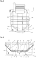
- the gravity flow channel 5 has a cross section comprising a central portion framed by two lateral portions.
- the cross-section of the channel 5 has a tangent tending to approach the vertical. This tends to cause a flow of water to "fall" towards the central portion of the channel 5.
- the central portion of the flow channel 5, as can be seen, has a shape tending to flatten, that is to say having a radius of curvature greater than that presented for example by the rounding of the transition part.
- part of the central portion is strictly flat, in particular a part which would be centered on the central portion.
- the bottom 21 and in particular the collection section 211 have a rectangular shape with a large length and a small width.
- the drainage channel 5 extends along the horizontal axis H.
- the drainage channel 5 thus has a significant length compared to the surface of the bottom 21 projected in a horizontal plane.
- the flow channel 5 is centered in the collection section 211.
- the flow channel 5 has a cross-section curved towards the outside of the tank 2. This shape allows the channel 5 to better resist external stresses and to accelerate the flow rate, which prevents the accumulation of residues in the bottom of the device.
- the tank 2 has an overflow 213 at the interface between the collection section 211 and the lifting section 212, and more precisely at the lowest end of the flow channel 5, towards the lifting section 212.
- the spillway 213 has a longitudinal section in an arc of a circle accelerating the speed of a flow of water leaving the gravity flow channel 5.
- the secondary part 202 of the tank 2 has a substantially cylindrical shape and has at its lower part a truncated housing 60, with a section decreasing towards the lifting section 212, to accommodate the pump 6.
- the lifting section 212 corresponds to the disc-shaped surface at the base of the frustoconical housing 60.
- the truncated cone shape makes it possible to maximize the grouping of the filtered water to be raised at the level of the pump, above the lifting section 212, and the resistance of this part of the tank 2, while presenting a secondary part 202 facilitating the maintenance of the lifting pump 6 (for example for its insertion/extraction) thanks to the larger diameter above the truncated cone part.
- the collection section 211 comprises two gravity flow sections 52 which frame the gravity flow channel 5. As can be seen in the Figure 6 , each gravity flow section 52 is inclined towards the gravity flow channel 5.
- these gravity flow sections 52 directly border the flow channel 5 by extending along the channel 5.
- the collection section 211 also comprises a front face 53 of gravity flow also inclined towards the channel 5, and located opposite the lifting section 212 relative to the flow channel 5.
- the collection section 211 comprises edges interposed between the channel 5 and the gravity flow sides 52.
- the device 1 comprises a base 7 for the tank 2.
- This base 7 delimits a laying plane 70 of the tank 2.
- the base of the housing 60 is at the level of this laying plane 70, thus allowing the lifting section 212 to be at the lowest height of the internal surface of the bottom, while not exceeding the height of the laying plane 70.
- this base 7 is formed by the rigid shell 20 of the tank 2.
- each beam 71 is formed by the rigid shell 20 which has a U-shaped section at the level of the beam 71.
- These beams 71 extend longitudinally along the collection section 211, and in particular along the channel 5.
- the beams 71 have, along their length, and from the laying plane 70 which they help to form, notches 711 reinforcing their structural resistance and allowing the passage of the forks of a lifting trolley.
- the stiffeners 72 extend transversely to the beams 71. They also have an external lower surface participating in forming the laying plane 70.
- stiffeners 72 are formed by the rigid shell 20 and contribute to the structural resistance of the tank 2.
- the device 1 comprises, according to the present embodiment, membranes 9 partially linked to the rigid shell 20.
- These membranes 9 are waterproof, and are for example glued to the rigid shell 20 at the edges and the gravity flow sides 52.
- the crevices formed by the beams 71 and the stiffeners 72 can be filled, for example with sand or water.
- the membranes 9 partially form the internal surface of the bottom 21 of the tank 2. In fact, the membranes 9 are coupled to the rigid shell 20 by being stretched above the crevices formed in particular by the beams 71 and the stiffeners 72.
- water filtered by the filtration stage 4 can flow along the membrane 9 to the gravity flow channel 5.
- the device 1 could comprise only a single membrane, which would for example also be glued in the gravity flow channel 5.
- the membrane(s) 9 are for example formed from EPDM rubber (acronym for ethylene-propylene-diene monomer).
- the base 7 provides a space above the installation plane 70 in which the gravity flow channel 5 extends.
- This space is notably formed between the two beams 71.
- the height of the base 7, and thus of the beams 71, allows the gravity flow channel 5 to have an optimized slope to form a flow of water towards the lifting section.
- device 1 includes a draining floor 8.
- the draining floor 8 can, for example, be formed by a honeycomb grid with vertical cells to which a geotextile felt is coupled to allow the filtered water to flow.
- This draining floor 8 is made, for example, of polyethylene.
- This draining floor 8 overhangs the gravity flow channel 5.
- the draining floor 8 rests on either side of the gravity flow channel 5, on the edges inserted between the channel 5 and the gravity flow sides 52.
- the device comprises ad hoc means allowing the filtered water flowing along the gravity flow sections 52 to pass the draining floor.
- These means may for example take the form of wedges raising the draining floor 8 from the edges, or of a filter foam having a reinforcement allowing it to support the filtering floor 8, or of a combination of the wedges and an excess of the geotextile felt of the draining floor 8.
- the draining floor 8 provides a free volume between it and the gravity flow channel 5.
- the device 1 also comprises vertical reinforcements 31 housed in the tank 2 and resting on the bottom 21 and on the upper wall 23 of the tank 2 which overhangs the bottom 21.
- each vertical reinforcement 31 rest on the bottom 21 via the draining floor 8. More precisely, each vertical reinforcement 31 is coupled to a crosspiece 310 extending transversely on the draining floor 8, parallel to the depth axis P, as illustrated by the Figure 4 .
- the device 1 previously described is used to form non-collective sanitation installations which is also an object of the invention.
- the pit dug in the ground must be of sufficient height to allow the insertion of tank 2, while allowing inspection points and a ventilation chimney to emerge from the surface of the surrounding ground.
- This pit must have a flat base on which the filtration device, and more specifically the tank 2, rests by means of the base 7.
- This flat base can in particular be formed by a raft.
- the backfill material is used to fill the pit, around the filtration device 1.
- This backfill material can, for example, correspond to part of the earth from the excavation of the pit.
- the filtration device 1 and the installation previously described have a significant capacity to resist fouling thanks to the bottom of the tank 2 which makes it possible to easily flush, in the direction of the lifting pump for evacuation, unfiltered particles likely to create fouling, under the effect of a flow of filtered water.
- This solution takes effect as soon as water flows into the filtration tank, and does not require one-off intervention by a human operator in the tank to initiate it.
Landscapes
- Life Sciences & Earth Sciences (AREA)
- Chemical & Material Sciences (AREA)
- Water Supply & Treatment (AREA)
- Engineering & Computer Science (AREA)
- Hydrology & Water Resources (AREA)
- Chemical Kinetics & Catalysis (AREA)
- Public Health (AREA)
- Health & Medical Sciences (AREA)
- Microbiology (AREA)
- Environmental & Geological Engineering (AREA)
- Organic Chemistry (AREA)
- Biodiversity & Conservation Biology (AREA)
- Sewage (AREA)
- Filtration Of Liquid (AREA)
Applications Claiming Priority (1)
| Application Number | Priority Date | Filing Date | Title |
|---|---|---|---|
| FR2309690A FR3153000A1 (fr) | 2023-09-14 | 2023-09-14 | Dispositif de filtration d’eaux usées pour installation d’assainissement non collectif |
Publications (1)
| Publication Number | Publication Date |
|---|---|
| EP4524110A1 true EP4524110A1 (de) | 2025-03-19 |
Family
ID=89767578
Family Applications (1)
| Application Number | Title | Priority Date | Filing Date |
|---|---|---|---|
| EP24197025.0A Pending EP4524110A1 (de) | 2023-09-14 | 2024-08-28 | Abwasserfiltervorrichtung für eine kleinkläranlage |
Country Status (2)
| Country | Link |
|---|---|
| EP (1) | EP4524110A1 (de) |
| FR (1) | FR3153000A1 (de) |
Citations (7)
| Publication number | Priority date | Publication date | Assignee | Title |
|---|---|---|---|---|
| FR2817856A1 (fr) * | 2000-12-11 | 2002-06-14 | Eparco Assainissement | Installation de traitement d'eaux usees avec systeme limiteur de debit amont et systeme limiteur de debit aval |
| FR2993552A1 (fr) * | 2012-07-18 | 2014-01-24 | Neropure | Dispositif pour le traitement des effluents liquides |
| FR2999625A1 (fr) | 2012-12-17 | 2014-06-20 | P R D | Cuve de traitement d'eaux destinee a etre enterree, comprenant une paroi externe presentant des elements en saillie |
| US10167216B2 (en) * | 2012-09-14 | 2019-01-01 | Gregory D. Graves | High efficiency wastewater treatment system |
| CN112081214A (zh) * | 2020-09-21 | 2020-12-15 | 南京沃谱瑞环境研究院有限公司 | 一种海绵城市用地下排水装置 |
| CN114592578A (zh) * | 2022-03-28 | 2022-06-07 | 中国水利水电第十一工程局有限公司 | 一种海绵城市用的绿化沟 |
| EP4079390A1 (de) * | 2021-04-23 | 2022-10-26 | Innoclair | Vorrichtung zum filtern von abwasser für eine nicht-kollektive abwasseraufbereitungsanlage |
-
2023
- 2023-09-14 FR FR2309690A patent/FR3153000A1/fr active Pending
-
2024
- 2024-08-28 EP EP24197025.0A patent/EP4524110A1/de active Pending
Patent Citations (8)
| Publication number | Priority date | Publication date | Assignee | Title |
|---|---|---|---|---|
| FR2817856A1 (fr) * | 2000-12-11 | 2002-06-14 | Eparco Assainissement | Installation de traitement d'eaux usees avec systeme limiteur de debit amont et systeme limiteur de debit aval |
| FR2993552A1 (fr) * | 2012-07-18 | 2014-01-24 | Neropure | Dispositif pour le traitement des effluents liquides |
| US10167216B2 (en) * | 2012-09-14 | 2019-01-01 | Gregory D. Graves | High efficiency wastewater treatment system |
| FR2999625A1 (fr) | 2012-12-17 | 2014-06-20 | P R D | Cuve de traitement d'eaux destinee a etre enterree, comprenant une paroi externe presentant des elements en saillie |
| CN112081214A (zh) * | 2020-09-21 | 2020-12-15 | 南京沃谱瑞环境研究院有限公司 | 一种海绵城市用地下排水装置 |
| EP4079390A1 (de) * | 2021-04-23 | 2022-10-26 | Innoclair | Vorrichtung zum filtern von abwasser für eine nicht-kollektive abwasseraufbereitungsanlage |
| FR3122101A1 (fr) | 2021-04-23 | 2022-10-28 | Innoclair | Dispositif de filtration d’eaux usées pour installation d’assainissement non collectif |
| CN114592578A (zh) * | 2022-03-28 | 2022-06-07 | 中国水利水电第十一工程局有限公司 | 一种海绵城市用的绿化沟 |
Also Published As
| Publication number | Publication date |
|---|---|
| FR3153000A1 (fr) | 2025-03-21 |
Similar Documents
| Publication | Publication Date | Title |
|---|---|---|
| EP0279140B1 (de) | Technischer Modul für Schwimmbäder | |
| FR2927913A1 (fr) | Element prefabrique en beton destine a la realisation d'un reservoir de recuperation et/ou de retention d'eau pluviale | |
| EP2307624B1 (de) | Automatisches und sich schnell öffnendes system für volltankablass | |
| EP4524110A1 (de) | Abwasserfiltervorrichtung für eine kleinkläranlage | |
| EP1019600B1 (de) | Filter- und pumpenvorrichtung für überlauf-schwimmbäder | |
| EP0770735B1 (de) | Unterirdischer Pufferbehälter zum Lagern und Behandeln von Regenwasser | |
| EP1905904A1 (de) | System zur Rückgewinnung von Regenwasser | |
| CA2529641C (fr) | Procede de digestion anaerobie de boues et digesteur | |
| FR2965835A1 (fr) | Installation comprenant un poste de transformation electrique et un systeme ameliore de separation des eaux pluviales et de l'huile de fuite | |
| EP4079390A1 (de) | Vorrichtung zum filtern von abwasser für eine nicht-kollektive abwasseraufbereitungsanlage | |
| FR2907022A1 (fr) | Unite de traitement modulaire | |
| EP4079983B1 (de) | Hebestation für abwasser mit verstärktem boden | |
| FR2917725A1 (fr) | Systeme d'accumulation | |
| EP1722039A1 (de) | Vorrichtung zum Lagern von Regenwasser | |
| LU500135B1 (fr) | Système en béton de freinage de décharge d'eau | |
| EP3636857A1 (de) | Vorrichtung zur oberflächenabschöpfung für schwimmbad, und mit einer solchen vorrichtung ausgestattetes schwimmbad | |
| FR3106504A1 (fr) | Bâtiment dépolluant. | |
| EP1484095A2 (de) | Absetzbecken zur Behandlung von Abflüssen | |
| FR3046158A1 (fr) | Dispositif de traitement d'eaux usees par filtres a plantes du type roseaux | |
| EP4069817B1 (de) | Verbesserte methanisierungseinheit | |
| FR3144631A1 (fr) | Dispositif d’ecumage pour bassin a debordement | |
| FR2728926A1 (fr) | Caveau monobloc en materiau composite | |
| EP0688904A1 (de) | Schleusentor | |
| FR2944814A1 (fr) | Separateur a hydrocarbures destine au traitement d'eaux de ruissellement | |
| EP4459076A1 (de) | Schwimmbeckeninstallation mit pufferrohren zur wasserspeicherung aus einem wasserrückgewinnungsnetzwerk |
Legal Events
| Date | Code | Title | Description |
|---|---|---|---|
| PUAI | Public reference made under article 153(3) epc to a published international application that has entered the european phase |
Free format text: ORIGINAL CODE: 0009012 |
|
| STAA | Information on the status of an ep patent application or granted ep patent |
Free format text: STATUS: THE APPLICATION HAS BEEN PUBLISHED |
|
| AK | Designated contracting states |
Kind code of ref document: A1 Designated state(s): AL AT BE BG CH CY CZ DE DK EE ES FI FR GB GR HR HU IE IS IT LI LT LU LV MC ME MK MT NL NO PL PT RO RS SE SI SK SM TR |
|
| STAA | Information on the status of an ep patent application or granted ep patent |
Free format text: STATUS: REQUEST FOR EXAMINATION WAS MADE |
|
| 17P | Request for examination filed |
Effective date: 20250403 |