EP4524227A1 - Dispositif et procédé de mesure - Google Patents
Dispositif et procédé de mesure Download PDFInfo
- Publication number
- EP4524227A1 EP4524227A1 EP22941668.0A EP22941668A EP4524227A1 EP 4524227 A1 EP4524227 A1 EP 4524227A1 EP 22941668 A EP22941668 A EP 22941668A EP 4524227 A1 EP4524227 A1 EP 4524227A1
- Authority
- EP
- European Patent Office
- Prior art keywords
- reflection
- measuring device
- heat conduction
- substrate
- conduction plate
- Prior art date
- Legal status (The legal status is an assumption and is not a legal conclusion. Google has not performed a legal analysis and makes no representation as to the accuracy of the status listed.)
- Pending
Links
Images





Classifications
-
- B—PERFORMING OPERATIONS; TRANSPORTING
- B01—PHYSICAL OR CHEMICAL PROCESSES OR APPARATUS IN GENERAL
- B01L—CHEMICAL OR PHYSICAL LABORATORY APPARATUS FOR GENERAL USE
- B01L7/00—Heating or cooling apparatus; Heat insulating devices
- B01L7/52—Heating or cooling apparatus; Heat insulating devices with provision for submitting samples to a predetermined sequence of different temperatures, e.g. for treating nucleic acid samples
-
- G—PHYSICS
- G01—MEASURING; TESTING
- G01N—INVESTIGATING OR ANALYSING MATERIALS BY DETERMINING THEIR CHEMICAL OR PHYSICAL PROPERTIES
- G01N21/00—Investigating or analysing materials by the use of optical means, i.e. using sub-millimetre waves, infrared, visible or ultraviolet light
- G01N21/62—Systems in which the material investigated is excited whereby it emits light or causes a change in wavelength of the incident light
- G01N21/63—Systems in which the material investigated is excited whereby it emits light or causes a change in wavelength of the incident light optically excited
- G01N21/64—Fluorescence; Phosphorescence
- G01N21/6428—Measuring fluorescence of fluorescent products of reactions or of fluorochrome labelled reactive substances, e.g. measuring quenching effects, using measuring "optrodes"
-
- C—CHEMISTRY; METALLURGY
- C12—BIOCHEMISTRY; BEER; SPIRITS; WINE; VINEGAR; MICROBIOLOGY; ENZYMOLOGY; MUTATION OR GENETIC ENGINEERING
- C12Q—MEASURING OR TESTING PROCESSES INVOLVING ENZYMES, NUCLEIC ACIDS OR MICROORGANISMS; COMPOSITIONS OR TEST PAPERS THEREFOR; PROCESSES OF PREPARING SUCH COMPOSITIONS; CONDITION-RESPONSIVE CONTROL IN MICROBIOLOGICAL OR ENZYMOLOGICAL PROCESSES
- C12Q1/00—Measuring or testing processes involving enzymes, nucleic acids or microorganisms; Compositions therefor; Processes of preparing such compositions
- C12Q1/68—Measuring or testing processes involving enzymes, nucleic acids or microorganisms; Compositions therefor; Processes of preparing such compositions involving nucleic acids
- C12Q1/6844—Nucleic acid amplification reactions
- C12Q1/6851—Quantitative amplification
-
- C—CHEMISTRY; METALLURGY
- C12—BIOCHEMISTRY; BEER; SPIRITS; WINE; VINEGAR; MICROBIOLOGY; ENZYMOLOGY; MUTATION OR GENETIC ENGINEERING
- C12Q—MEASURING OR TESTING PROCESSES INVOLVING ENZYMES, NUCLEIC ACIDS OR MICROORGANISMS; COMPOSITIONS OR TEST PAPERS THEREFOR; PROCESSES OF PREPARING SUCH COMPOSITIONS; CONDITION-RESPONSIVE CONTROL IN MICROBIOLOGICAL OR ENZYMOLOGICAL PROCESSES
- C12Q1/00—Measuring or testing processes involving enzymes, nucleic acids or microorganisms; Compositions therefor; Processes of preparing such compositions
- C12Q1/68—Measuring or testing processes involving enzymes, nucleic acids or microorganisms; Compositions therefor; Processes of preparing such compositions involving nucleic acids
- C12Q1/6844—Nucleic acid amplification reactions
- C12Q1/686—Polymerase chain reaction [PCR]
-
- G—PHYSICS
- G01—MEASURING; TESTING
- G01N—INVESTIGATING OR ANALYSING MATERIALS BY DETERMINING THEIR CHEMICAL OR PHYSICAL PROPERTIES
- G01N1/00—Sampling; Preparing specimens for investigation
- G01N1/28—Preparing specimens for investigation including physical details of (bio-)chemical methods covered elsewhere, e.g. G01N33/50, C12Q
- G01N1/44—Sample treatment involving radiation, e.g. heat
-
- G—PHYSICS
- G01—MEASURING; TESTING
- G01N—INVESTIGATING OR ANALYSING MATERIALS BY DETERMINING THEIR CHEMICAL OR PHYSICAL PROPERTIES
- G01N33/00—Investigating or analysing materials by specific methods not covered by groups G01N1/00 - G01N31/00
- G01N33/48—Biological material, e.g. blood, urine; Haemocytometers
- G01N33/50—Chemical analysis of biological material, e.g. blood, urine; Testing involving biospecific ligand binding methods; Immunological testing
- G01N33/58—Chemical analysis of biological material, e.g. blood, urine; Testing involving biospecific ligand binding methods; Immunological testing involving labelled substances
- G01N33/582—Chemical analysis of biological material, e.g. blood, urine; Testing involving biospecific ligand binding methods; Immunological testing involving labelled substances with fluorescent label
-
- B—PERFORMING OPERATIONS; TRANSPORTING
- B01—PHYSICAL OR CHEMICAL PROCESSES OR APPARATUS IN GENERAL
- B01L—CHEMICAL OR PHYSICAL LABORATORY APPARATUS FOR GENERAL USE
- B01L2300/00—Additional constructional details
- B01L2300/08—Geometry, shape and general structure
- B01L2300/0809—Geometry, shape and general structure rectangular shaped
- B01L2300/0819—Microarrays; Biochips
-
- B—PERFORMING OPERATIONS; TRANSPORTING
- B01—PHYSICAL OR CHEMICAL PROCESSES OR APPARATUS IN GENERAL
- B01L—CHEMICAL OR PHYSICAL LABORATORY APPARATUS FOR GENERAL USE
- B01L2300/00—Additional constructional details
- B01L2300/16—Surface properties and coatings
- B01L2300/168—Specific optical properties, e.g. reflective coatings
-
- B—PERFORMING OPERATIONS; TRANSPORTING
- B01—PHYSICAL OR CHEMICAL PROCESSES OR APPARATUS IN GENERAL
- B01L—CHEMICAL OR PHYSICAL LABORATORY APPARATUS FOR GENERAL USE
- B01L2300/00—Additional constructional details
- B01L2300/18—Means for temperature control
- B01L2300/1805—Conductive heating, heat from thermostatted solids is conducted to receptacles, e.g. heating plates, blocks
-
- G—PHYSICS
- G01—MEASURING; TESTING
- G01N—INVESTIGATING OR ANALYSING MATERIALS BY DETERMINING THEIR CHEMICAL OR PHYSICAL PROPERTIES
- G01N21/00—Investigating or analysing materials by the use of optical means, i.e. using sub-millimetre waves, infrared, visible or ultraviolet light
- G01N21/62—Systems in which the material investigated is excited whereby it emits light or causes a change in wavelength of the incident light
- G01N21/63—Systems in which the material investigated is excited whereby it emits light or causes a change in wavelength of the incident light optically excited
- G01N21/64—Fluorescence; Phosphorescence
- G01N21/6428—Measuring fluorescence of fluorescent products of reactions or of fluorochrome labelled reactive substances, e.g. measuring quenching effects, using measuring "optrodes"
- G01N2021/6439—Measuring fluorescence of fluorescent products of reactions or of fluorochrome labelled reactive substances, e.g. measuring quenching effects, using measuring "optrodes" with indicators, stains, dyes, tags, labels, marks
Definitions
- the present invention relates to a measuring device and a measuring method, and particularly to digital PCR.
- PCR or real-time PCR has been used for genetic testing. These technologies have a problem that measurement accuracy is low when a measurement target (nucleic acid) is in a trace amount. To solve this problem, digital PCR technology has recently attracted attention.
- a sample containing DNA to be detected is divided into a large number of minute regions, and PCR is performed on each minute region.
- the type of DNA present in each minute region is identified by performing discrimination between the segment containing the DNA to be detected and the segment not containing the DNA based on fluorescence intensity.
- PTL 1 discloses, as a DNA detection method using digital PCR, a DNA detection method for measuring a melting temperature between DNA and a fluorescence-labeled probe that hybridizes to DNA in a droplet containing the DNA and the fluorescence-labeled probe.
- melting curve analysis there are a plurality of types of genes to be measured, and examples thereof include wild-type and mutant-type genes. Since the melting curve differs depending on the type of the target gene and the fluorescence-labeled probe, it is possible to identify the type of the target gene by measuring the melting curve. In the case of simultaneously measuring a large number of genes, it is necessary to measure fluorescence intensity and a melting curve with high accuracy to reduce measurement variations of each gene.
- An object of the present invention is to provide a measuring device capable of suppressing unevenness of a fluorescence image and fluctuation of fluorescence intensity caused by an influence of air bubbles in melting curve analysis of a target gene.
- An example of a measuring device includes:
- a measuring method according to the present invention is a measuring method using a measuring device, the measuring device including:
- the present invention can provide a measuring device and a measuring method capable of suppressing the influence of air bubbles, measuring the fluorescence intensity and the melting curve with high accuracy, and identifying the type of gene with high accuracy.
- FIGS. 1 and 2 A conventional example will be described with reference to FIGS. 1 and 2 .
- FIG. 1 is a schematic view of a conventional measuring device holding a through-hole well 1 when fluorescence is measured.
- This measuring device includes a substrate 2 holding a plurality of through-hole wells 1, a mixed solution 3 of nucleic acid injected into the wells and a fluorescence-labeled probe, an oil 4 covering the through-hole wells 1, and a heat conduction plate 5.
- excitation light 6 is emitted to the through-hole wells 1.
- a part of the excitation light 6 becomes transmitted light 7 passing through the through-hole wells 1.
- the transmitted light 7 is reflected by the heat conduction plate 5 to become reflected light 8.
- the reflected light 8 passes through the through-hole wells 1 again.
- a reflected light intensity 10 is measured as the measurement light intensity of the wells together with a fluorescence intensity 9.
- the transmitted light 7 of the through-hole well 1 is diffused in the lower portion of the through-hole well 1 by the air bubble 11.
- light 12 that is not reflected by the heat conduction plate 5 is not detected as strong as the reflected light intensity 10. That is, when the air bubble is present, the measured light intensity is the sum of the fluorescence intensity 9 and the reflected light intensity 13 attenuated as compared with the original reflected light intensity 10.
- FIG. 2 includes reflection images obtained by observing a substrate 101 holding a through-hole well 100 at a low magnification ( FIG. 2(a) ) and a high magnification ( FIG. 2(b) ).
- the reflection image of the through-hole well 100 is bright.
- the excitation light 6 passes through the through-hole well 1 and reflected by the heat conduction plate 5.
- the through-hole well 100 and a through-hole well 102 are compared, there is a variation in brightness. This is due to in-plane variation in reflectance of the heat conduction plate 5.
- Example 1 will be described with reference to FIGS. 3 and 4 .
- the heat conduction plate is subjected to blackening treatment, which makes air bubbles difficult to be observed.
- Using the measuring device according to the present example makes it possible to measure the fluorescence intensity without the influence of air bubbles.
- FIG. 3 is a schematic view illustrating that applying a black surface treatment film 201 to a heat conduction plate 200 at a lower portion of the measuring device makes an air bubble 202 observed in FIG. 1 difficult to be observed.
- the measuring device includes a substrate 209 having a plurality of through-hole wells 203 (through-holes) for introducing and dividing a mixed solution 208.
- the measuring device has an oil 210 covering a first surface 209a of the substrate 209 and a second surface 209b on the opposite side from the first surface of the substrate to close the through-hole wells 203.
- the mixed solution 208 includes a nucleic acid solution.
- a reference to a mixed solution can be interpreted as a reference to a nucleic acid solution.
- the measuring device includes a heat conduction plate 200 provided on the second surface 209b side to change the temperature of the substrate 209 (for example, to heat the substrate 209). It can be said that the second surface 209b is a surface of the substrate 209 on the heat conduction plate 200 side.
- the material of the heat conduction plate 200 is, for example, metal or resin, or it may be glass. Using such a material makes it possible to configure a heat conduction plate suitable for the requirements of the measuring device. Other materials may also be used.
- the measuring device has a reflection-suppressing mechanism that suppresses reflection of excitation light 207 emitted from the first surface 209a side (for example, reflection to the first surface 209a side) .
- the reflection suppressing mechanism is a colored surface treatment structure of the heat conduction plate 200.
- the reflection-suppressing mechanism includes a black surface treatment film 201 as a reflection-suppressing film.
- the surface treatment film 201 is disposed on the heat conduction plate 200.
- the surface treatment film 201 absorbs excitation light (or light having the same wavelength as the excitation light).
- Applying the black surface treatment film 201 to the heat conduction plate 200 causes reflected light 204 from the heat conduction plate 200 to generate attenuated reflected light intensity 205.
- the measured light intensity of each through-hole well 203 is the sum of the fluorescence intensity 206 and the attenuated reflected light intensity 205. Therefore, the air bubbles are prevented from being observed as unevenness on the measurement image.
- the structure and forming method of the surface treatment film 201 can be appropriately designed by those skilled in the art.
- the thickness of the surface treatment film 201 varies depending on the surface treatment step.
- an anodized film such as a film formed through an alumite treatment has a thickness of about 5 to 40 ⁇ m
- a film formed through electroplating has a thickness of about 2 to 20 ⁇ m.
- the thickness of a film formed through spray coating is about 15 to 30 ⁇ m. In the case of the present example, the film thickness is desirably 40 ⁇ m or less.
- FIG. 4 includes reflection images obtained by observing a substrate 300 after applying the black surface treatment film 201 to the heat conduction plate at low magnification ( FIG. 4(a) ) and high magnification ( FIG. 4(b) ).
- the reflection image in a through-hole well 301 is dark.
- the reflected light intensity between the through-hole well 301 and a through-hole well 302 it can be seen that there is no variation in the reflected light intensity.
- the reflected light intensity is small as a whole. From this reflection image, it can be said that reflection from the heat conduction plate 200 is suppressed.
- the black surface treatment film 201 is used as the colored surface treatment structure.
- the reflectance thereof is important.
- "colored" means that the reflectance is 10% or less over a wavelength of 400 nm to 700 nm, for example, and means black as a specific example. With such a colored surface treatment structure, reflection from the heat conduction plate 200 is suppressed.
- the measuring device can suppress the unevenness of the fluorescence image and the fluctuation in the fluorescence intensity caused by the influence of air bubbles in the melting curve analysis of the target gene.
- Example 2 will be described with reference to FIGS. 5 and 6 .
- fine particles 401 are injected into the lower portion of a through-hole well 400, which makes an air bubble 402 difficult to be observed.
- Using the measuring device according to the present example makes it possible to measure the fluorescence intensity without the influence of the air bubble 402.
- description of parts common to Example 1 may be omitted.
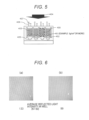
- FIG. 5 is a schematic view illustrating a state where fluorescence measurement is performed in a case where fine particles 401 are introduced into a lower portion of a mixed solution 403 of a nucleic acid and a fluorescence-labeled probe injected into the through-hole well 400 in the measuring device.
- the reflection-suppressing mechanism according to the present example includes the fine particles 401 introduced into the through-hole well 400. It is preferable that the fine particles 401 do not allow excitation light 404 to pass therethrough.
- the measured light intensity is the sum of a fluorescence intensity 406 and an attenuated reflected light intensity 407. This makes the air bubble 402 difficult to be observed in the measurement image.
- FIG. 6 illustrates a comparison between reflection images of the measuring devices illustrated in FIGS. 1 and 5.
- FIG. 6(a) is a reflection image obtained by observing a conventional measuring device.
- FIG. 6(b) is a reflection image obtained by observing a measuring device according to the present example into which fine particles are injected.
- the average reflected light intensity averaged for 50 through-hole wells was 133 (any unit).
- the average reflected light intensity was 99.
- the average reflected light intensity of the plurality of through-hole wells is focused, the average reflected light intensity of the plurality of wells is decreased by injecting fine particles into the through-hole wells. Thus, excitation light is prevented from passing through the through-hole well and being reflected on the heat conduction plate.
- Conditions of the fine particles to be injected include size, specific gravity, surface treatment, and number.
- the size (for example, diameter) is desirably 30 nm or more.
- the scattering phenomenon is based on Mie scattering theory. Since Mie scattering shows significant scattering intensity from about 30 nm, this value can be set as a lower limit value.
- the size of the fine particles is preferably smaller than that of the through-hole well into which the fine particles are injected. Thus, when the well size is 60 ⁇ m, the upper limit value of the fine particles can be 60 ⁇ m.
- the fine particles settle at the bottom of the through-hole well.
- fine particles having a specific gravity larger than 1 such as polymer fine particles (polystyrene, specific gravity: 1.04 to 1.07 g/cm 3 ), magnetic fine particles (iron, specific gravity: 7.85 g/cm 3 ), and metal fine particles (silver, specific gravity: 10.49 g/cm 3 ), are used as the fine particles (that is, the specific gravity of the fine particles is 1 g/cm 3 or more). In such a case, the fine particles settle in the through-hole well.
- polymer fine particles polystyrene, specific gravity: 1.04 to 1.07 g/cm 3
- magnetic fine particles iron, specific gravity: 7.85 g/cm 3
- metal fine particles silver, specific gravity: 10.49 g/cm 3
- the mixed solution of a nucleic acid and a fluorescence-labeled probe is a watersoluble solution, it is suitable that the fine particles are hydrophilically treated (for example, hydrophilically coated). To prevent the nucleic acid from being adsorbed to the fine particle, it is preferable to negatively charge the surfaces of the fine particles.
- a treatment of disposing a carboxy group on the surfaces of the fine particles is performed so that the fine particle exhibits hydrophilicity.
- a condition that the fine particle sectional area ⁇ the number of injections is equal to or less than the bottom area of the through-hole well: (fine particle sectional area) ⁇ (number of fine particles to be injected) ⁇ (through-hole well bottom area) is preferably satisfied. It is not always necessary to cover the entire bottom area of the through-hole well with fine particles. In one example, it has been confirmed that the influence of air bubbles is reduced using the condition that about 10% of the bottom area of the well is covered with fine particles.
- the measuring device can suppress the unevenness of the fluorescence image and the fluctuation in the fluorescence intensity caused by the influence of air bubbles in the melting curve analysis of the target gene.
- Example 3 will be described with reference to FIG. 7 .
- the lower portion of the measuring device is formed into a transparent heat conduction plate 500, which makes an air bubble 501 difficult to be observed.
- Using the measuring device according to the present example makes it possible to measure the fluorescence intensity without the influence of the air bubble 501.
- description of parts common to Examples 1 and 2 may be omitted.
- FIG. 7 is a schematic view illustrating a state where fluorescence is measured in a case where the lower portion of the measuring device is formed into the transparent heat conduction plate 500.
- Excitation light 502 passes through a through-hole well 503 and reaches the transparent heat conduction plate 500. At this time, the excitation light 502 becomes light 504 passing through the heat conduction plate 500 because of the transparent heat conduction plate. This makes it possible to suppress reflection of excitation light.
- the measured light intensity is the sum of a fluorescence intensity 505 and an attenuated reflected light intensity 506. This makes the air bubble 501 difficult to be observed in the measurement image.
- the transparent heat conduction plate 500 examples include plastic such as polycarbonate and glass.
- the transparent heat conduction plate 500 may be a transparent conductive substrate obtained by doping a glass substrate with indium tin oxide or the like.
- the measuring device can suppress the unevenness of the fluorescence image and the fluctuation in the fluorescence intensity caused by the influence of air bubbles in the melting curve analysis of the target gene.
- Example 4 will be described with reference to FIG. 8 .
- a heat conduction plate 600 having an uneven structure is used, which makes an air bubble 601 difficult to be observed.
- Using the measuring device according to the present example makes it possible to measure the fluorescence intensity without the influence of the air bubble 601.
- description of parts common to Examples 1 to 3 may be omitted.
- FIG. 8 is a schematic view illustrating a state where fluorescence is measured in a case where the heat conduction plate 600 having an uneven structure is used as the lower portion of the measuring device.
- the reflection-suppressing mechanism according to the present example includes an uneven structure, and the uneven structure is disposed on the heat conduction plate 600 having an uneven structure.
- Excitation light 602 passes through a through-hole well 603 and reaches the heat conduction plate 600 having an uneven structure. At this time, reflected light 604 of the excitation light can be suppressed by the uneven structure.
- the measured light intensity is the sum of a fluorescence intensity 605 and an attenuated reflected light intensity 606. This makes the air bubble 601 difficult to be observed in the measurement image.
- the structure is periodic. It is more preferable that the pitch (spatial repetition period) of the uneven structure is 1 ⁇ m or less.
- the measuring device can suppress the unevenness of the fluorescence image and the fluctuation in the fluorescence intensity caused by the influence of air bubbles in the melting curve analysis of the target gene.
- Example 5 will be described with reference to FIG. 9 .
- the oil covering the through-holes is colored, which makes an air bubble 700 difficult to be observed.
- Using the measuring device according to the present example makes it possible to measure the fluorescence intensity without the influence of the air bubble 700.
- description of parts common to Examples 1 to 4 may be omitted.
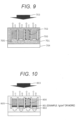
- FIG. 9 is a schematic view illustrating a state where fluorescence is measured in a case where a through-hole well 702 is covered with a colored oil 701 in the measuring device.
- the oil 701 is colored in black.
- the colored oil 701 is not necessarily limited to those subjected to the coloring treatment, and the color is not limited to black.
- Excitation light 703 is absorbed by the colored oil 701.
- reflected light 705 from a heat conduction plate 704 can be suppressed.
- the reflectance of the coloring pigment is important in the coloring of the oil.
- "colored" means that the reflectance is 10% or less over a wavelength of 400 nm to 700 nm, for example. With such a reflectance, reflection of the excitation light can be efficiently suppressed.
- the oil 701 may actually be present on the upper side of the through-hole well 702, and in such a case, fluorescence may also be shielded.
- the reflectance of the excitation light and the fluorescence in the oil 701 is 10%, and the transmittance is 10%.
- 10% is incident on the through-hole well 702, 1% is reflected at the lower end of the through-hole well 702, and 0.1% is transmitted to the upper side of the through-hole well 702 and detected.
- 10% is transmitted to the upper side of the through-hole well 702 and detected. In this manner, it can be said that the excitation light is negligible with respect to the fluorescence on the upper side of the through-hole well 702, and the reflection of the excitation light is efficiently suppressed.
- the measuring device can suppress the unevenness of the fluorescence image and the fluctuation in the fluorescence intensity caused by the influence of air bubbles in the melting curve analysis of the target gene.
- Example 6 will be described with reference to FIG. 10 .
- an ink 801 is introduced into the lower portion of a through-hole well 800, which makes an air bubble 802 difficult to be observed.
- Using the measuring device according to the present example makes it possible to measure the fluorescence intensity without the influence of the air bubble 802.
- description of parts common to Examples 1 to 5 may be omitted.
- FIG. 10 is a schematic view illustrating a state where fluorescence is measured in a case where the ink 801 is injected into the lower portion of the through-hole well 800.
- the reflection-suppressing mechanism includes the ink 801 introduced into the through-hole well 800. After passing through the through-hole well 800, excitation light 803 is absorbed by the ink 801. This makes the air bubble 802 difficult to be observed in the measurement image.
- the ink 801 is desirably a pigment ink.
- the specific gravity is preferably larger than that of the mixed solution of a nucleic acid and a fluorescence-labeled probe as the condition determined from the viewpoint of the specific gravity. That is, it is preferable that the ink 801 has a specific gravity larger than that of a mixed solution 805. Satisfying this condition makes it possible to cause the ink to settle to the lower portion of the through-hole well.
- the specific gravity of the ink 801 is preferably 1 g/cm 3 or more.
- carbon black specifically gravity: 1.7 to 1.8 g/cm 3
- the like may be used as the pigment ink.
- the measuring device can suppress the unevenness of the fluorescence image and the fluctuation in the fluorescence intensity caused by the influence of air bubbles in the melting curve analysis of the target gene.
- Example 7 shows an effect that air bubbles are not actually observed by using the measuring device according to Example 1.
- the measuring device is heated for a certain period of time so as to be maintained at 85°C.
- the measuring device is irradiated with excitation light in the visible range to acquire a fluorescence image.
- the exposure time at the time of fluorescence image acquisition is 1300 ms. 80 or more fluorescence images are continuously photographed to evaluate the presence or absence of the influence of air bubbles.
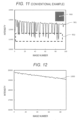
- FIG. 11 illustrates a fluorescence intensity change 901 of a single well 900 in the measuring device illustrated in FIG. 1 not provided with the reflection-suppressing mechanism as a comparative example.
- a part of the fluorescence image of the through-hole well is illustrated in the upper right of the graph (only the single well 900 is modified white for visibility).
- the horizontal axis represents the number of fluorescence images
- the vertical axis represents the fluorescence intensity.
- the image number represents the order in which the images were acquired, and thus, the horizontal axis corresponds to time.
- the data in the graph is the fluorescence intensity change of the single well 900 in each fluorescence image.
- the fluorescence intensity does not always show a constant value, and a steep fluorescence intensity change 902 occurs.
- this steep fluorescence intensity change 902 occurs, air bubbles are present in the lower portion of the well.
- the presence of air bubbles can be confirmed from the steep fluorescence intensity change 902 of the fluorescence intensity.
- FIG. 12 illustrates a fluorescence intensity change 1000 of a single well in the measuring device according to Example 1 to which the reflection-suppressing mechanism is applied. It can be seen that a steep change in fluorescence intensity is not observed as compared with the case of FIG. 11 . Thus, it is possible to suppress the influence of air bubbles by using Example 1. It is considered that the same effect is obtained from the measuring device according to Examples 2 to 6.
- the measuring device can suppress the unevenness of the fluorescence image and the fluctuation in the fluorescence intensity caused by the influence of air bubbles in the melting curve analysis of the target gene.
- Example 8 illustrates a measuring method for melting curve analysis using the measuring device of Examples 1 to 6. Using the measuring device according to the present example makes it possible to measure melting curve analysis with high accuracy.
- FIG. 13 illustrates a measurement flow from injecting a mixed solution of a nucleic acid and a fluorescence-labeled probe into the measuring device according to the present example to performing melting curve analysis.
- a mixed solution of a nucleic acid and a fluorescence-labeled probe is introduced into the measuring device and fractionated into each of the through-hole wells to fractionate the nucleic acid into the through-hole wells (S1100).
- an oil is introduced in such a manner as to cover the periphery of the through-hole well (S1101).
- the oil is introduced to cover the first surface 209a of the substrate 209 and the second surface 209b on the opposite side from the first surface 209a of the substrate 209 to close the through-hole well 203 into which the mixed solution 208 has been introduced.
- PCR is performed to amplify the nucleic acid in the through-hole well (S1102).
- the temperature of the measuring device in particular, the temperature of the substrate 209 is changed by the heat conduction plate 200.
- the measurement device is irradiated with excitation light while the temperature is changed to detect the fluorescence intensity from the mixed solution of the nucleic acid and the fluorescence-labeled probe in the through-hole well (S1103).
- the excitation light 207 is emitted from the first surface 209a side of the substrate 209, and fluorescence is detected from the first surface 209a side, whereby the mixed solution 208 is measured.
- FIG. 14 illustrates an example of a melting curve analysis result in a conventional measuring device not provided with the reflection-suppressing mechanism as a comparative example.
- FIG. 14(a) is a graph in which the fluorescence intensity change with respect to temperature change in a single well in the measuring device is plotted. A decrease in fluorescence intensity can be confirmed. When air bubbles are observed during this decrease, a steep fluorescence intensity decrease 1200 is observed.
- FIG. 14(b) is obtained by differentiating the temperature with respect to the fluorescence intensity change of FIG. 14(a) , and a differential curve of the melting curve is calculated.
- the melting temperature is calculated from the peak of the differential curve.
- a true melting temperature 1201 but also a melting temperature artifact 1202 is observed. This artifact is caused from a steep fluorescence intensity decrease 1200.
- the influence of air bubbles greatly affects the melting curve analysis.
- FIG. 15 illustrates an example of a melting curve analysis result in the present example.
- the fluorescence intensity change with respect to the temperature change in a single well in the measuring device is plotted. A monotonic decrease in fluorescence intensity can be confirmed.
- FIG. 15(b) is obtained by differentiating the temperature with respect to the fluorescence intensity change of FIG. 15(a) .
- the measuring device of the present example air bubbles are hardly observed. Thereby, a steep decrease in fluorescence intensity or the like is hardly observed in the melting curve. Thus, only a true melting temperature 1300 is observed in the differential curve of the melting curve. Therefore, the measuring device according to the present example can suppress unnecessary artifacts, and highly accurate melting curve analysis can be performed.
- the measuring device and the measuring method according to the present example can suppress the unevenness of the fluorescence image and the fluctuation in the fluorescence intensity caused by the influence of air bubbles in the melting curve analysis of the target gene.
- Example 9 illustrates a method for confirming that the effect of making air bubbles difficult to be observed is obtained by blackening surface treatment on the heat conduction plate of Example 1 or injection of fine particles into through-hole wells of Example 2.
- FIG. 16 illustrates a measurement flow in which the operation of reflection image measurement is added to the measurement flow diagram of Example 8 illustrated in FIG. 13 .
- Steps S1400 to S1402 and S1404 in FIG. 16 can be the same as the steps S1100 to S1102 and S1103 in FIG. 13 , respectively.
- the reflection image of the measuring device is measured (S1403).
- the reflection image is measured by irradiating excitation light 207 or white light from the first surface 209a side of the substrate 209.
- the operation of the reflection image measurement is performed after PCR (S1402).
- the operation may be performed after an oil introduction step (S1401) of covering the through-hole.
- the step of S1403 can be performed after step S1401 and before step S1404 ends.
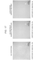
- FIG. 17 illustrates a reflection image actually observed in each measuring device.
- As the reflection image an image focused on the heat conduction plate is acquired.
- the coefficient of variation of the reflected light intensity is 10%.
- the coefficient of variation is a value obtained by dividing the standard deviation of the reflected light intensity by the average of the reflected light intensities for a plurality of through-hole wells.
- the coefficients of variation of the reflected light intensity are 3% and 4%, respectively.
- the coefficient of variation of the reflected light intensity decreases in the measuring device according to each example of the present invention.
- the performance of the measuring device according to the present example can be evaluated by evaluating the reflection image before performing the melting curve analysis.
- the measuring device and the measuring method according to the present example can suppress the unevenness of the fluorescence image and the fluctuation in the fluorescence intensity caused by the influence of air bubbles in the melting curve analysis of the target gene.
- the present invention is not limited to the above-described examples but includes various modifications.
- the above-described examples have been described in detail for easy understanding of the present invention, and the present invention is not necessarily limited to those having all the described configurations.
- a part of the configuration of a certain example can be replaced with the configuration of another example, and the configuration of a certain example can be added to the configuration of another example.
- a part of a configuration of each example can be added to, deleted from, and replaced with a part of another configuration.
Landscapes
- Chemical & Material Sciences (AREA)
- Health & Medical Sciences (AREA)
- Life Sciences & Earth Sciences (AREA)
- Engineering & Computer Science (AREA)
- Immunology (AREA)
- Physics & Mathematics (AREA)
- Organic Chemistry (AREA)
- General Health & Medical Sciences (AREA)
- Biochemistry (AREA)
- Analytical Chemistry (AREA)
- Chemical Kinetics & Catalysis (AREA)
- Molecular Biology (AREA)
- Wood Science & Technology (AREA)
- Proteomics, Peptides & Aminoacids (AREA)
- Zoology (AREA)
- Biotechnology (AREA)
- Pathology (AREA)
- Microbiology (AREA)
- General Physics & Mathematics (AREA)
- Genetics & Genomics (AREA)
- Bioinformatics & Cheminformatics (AREA)
- Biophysics (AREA)
- Urology & Nephrology (AREA)
- Hematology (AREA)
- Biomedical Technology (AREA)
- General Engineering & Computer Science (AREA)
- Medicinal Chemistry (AREA)
- Food Science & Technology (AREA)
- Cell Biology (AREA)
- Optics & Photonics (AREA)
- Nuclear Medicine, Radiotherapy & Molecular Imaging (AREA)
- Clinical Laboratory Science (AREA)
- Investigating, Analyzing Materials By Fluorescence Or Luminescence (AREA)
- Apparatus Associated With Microorganisms And Enzymes (AREA)
- Measuring Or Testing Involving Enzymes Or Micro-Organisms (AREA)
Applications Claiming Priority (1)
| Application Number | Priority Date | Filing Date | Title |
|---|---|---|---|
| PCT/JP2022/020026 WO2023218588A1 (fr) | 2022-05-12 | 2022-05-12 | Dispositif et procédé de mesure |
Publications (2)
| Publication Number | Publication Date |
|---|---|
| EP4524227A1 true EP4524227A1 (fr) | 2025-03-19 |
| EP4524227A4 EP4524227A4 (fr) | 2026-04-01 |
Family
ID=88730017
Family Applications (1)
| Application Number | Title | Priority Date | Filing Date |
|---|---|---|---|
| EP22941668.0A Pending EP4524227A4 (fr) | 2022-05-12 | 2022-05-12 | Dispositif et procédé de mesure |
Country Status (5)
| Country | Link |
|---|---|
| US (1) | US20250264408A1 (fr) |
| EP (1) | EP4524227A4 (fr) |
| JP (1) | JP7810791B2 (fr) |
| CN (1) | CN119013386A (fr) |
| WO (1) | WO2023218588A1 (fr) |
Family Cites Families (7)
| Publication number | Priority date | Publication date | Assignee | Title |
|---|---|---|---|---|
| JP2015169477A (ja) * | 2014-03-05 | 2015-09-28 | 大日本印刷株式会社 | 核酸増幅チップ |
| JP6812797B2 (ja) * | 2014-11-04 | 2021-01-13 | 凸版印刷株式会社 | 核酸導入方法、核酸検出方法、生体成分解析方法、生体成分定量用アレイデバイス、及び生体成分解析キット |
| JP6754301B2 (ja) * | 2017-01-05 | 2020-09-09 | 株式会社日立製作所 | ドロップレットデジタルpcrの測定方法および測定装置 |
| EP3560593B1 (fr) | 2018-04-25 | 2024-06-05 | OPTOLANE Technologies Inc. | Cartouche de pcr numérique en temps réel |
| JP7066540B2 (ja) * | 2018-06-14 | 2022-05-13 | 株式会社日立製作所 | デジタルpcrの測定方法および測定装置 |
| JP7164927B2 (ja) * | 2019-03-19 | 2022-11-02 | 株式会社日立製作所 | デジタルpcr計測装置 |
| JP7245734B2 (ja) * | 2019-06-26 | 2023-03-24 | 株式会社日立製作所 | デジタルpcrの測定方法および測定装置 |
-
2022
- 2022-05-12 EP EP22941668.0A patent/EP4524227A4/fr active Pending
- 2022-05-12 US US18/857,380 patent/US20250264408A1/en active Pending
- 2022-05-12 WO PCT/JP2022/020026 patent/WO2023218588A1/fr not_active Ceased
- 2022-05-12 JP JP2024520169A patent/JP7810791B2/ja active Active
- 2022-05-12 CN CN202280094804.5A patent/CN119013386A/zh active Pending
Also Published As
| Publication number | Publication date |
|---|---|
| JP7810791B2 (ja) | 2026-02-03 |
| CN119013386A (zh) | 2024-11-22 |
| WO2023218588A1 (fr) | 2023-11-16 |
| US20250264408A1 (en) | 2025-08-21 |
| EP4524227A4 (fr) | 2026-04-01 |
| JPWO2023218588A1 (fr) | 2023-11-16 |
Similar Documents
| Publication | Publication Date | Title |
|---|---|---|
| EP1248948B1 (fr) | Procede et dispositif pour la determination de parametres dependant de la temperature, tels que les parametres d'association/dissociation et/ou la constante d'equilibre de complexes constitues d'au moins deux composants | |
| US11662313B2 (en) | Microfluidic devices and observation methods | |
| US8143077B2 (en) | Microchip and method of manufacturing microchip | |
| US20190060897A1 (en) | Analysis devices, analysis kits, and analysis systems | |
| Weigert et al. | Combining HR-TEM and XPS to elucidate the core–shell structure of ultrabright CdSe/CdS semiconductor quantum dots | |
| US8718420B2 (en) | SPR sensor cell and SPR sensor | |
| EP2650670A1 (fr) | Cellule de capteur à résonance plasmonique de surface et capteur à résonance plasmonique de surface | |
| Lard et al. | Biosensing using arrays of vertical semiconductor nanowires: Mechanosensing and biomarker detection | |
| Ryu et al. | Ultrasensitive terahertz sensing of gold nanoparticles inside nano slot antennas | |
| DE112013003156T5 (de) | Durchflusszelle zur Biomaterialanalyse und Biomaterial-Analysevorrichtung | |
| EP4524227A1 (fr) | Dispositif et procédé de mesure | |
| AT513859A4 (de) | Mikro-Fluoreszenzdetektionsvorrichtung sowie Verfahren zur Detektion | |
| US9339813B2 (en) | Substance determining apparatus | |
| Liu et al. | Cylindrical illumination confocal spectroscopy: rectifying the limitations of confocal single molecule spectroscopy through one-dimensional beam shaping | |
| Peng et al. | Polyethylene imine-modified photonic crystal microfluidic chip for highly sensitive detection of microbial spores | |
| US20090238413A1 (en) | Method for quantifying metal colloid | |
| US12105022B2 (en) | Metal-based particle assembly, layered body and sensing apparatus | |
| JP5543485B2 (ja) | 流体中のターゲット成分を検出する検出装置 | |
| EP0585744B1 (fr) | Elément d'analyse guidant la lumière pour déterminer un analyte | |
| JP4910132B2 (ja) | 表面電荷量計測装置及び表面電荷量計測方法 | |
| DE102023209207A1 (de) | Diagnosesystem zur Analyse biologischer Proben | |
| Okura et al. | Surface-dependent quenching of Qdot emission can be a new tool for high resolution measurements | |
| Brownstein et al. | Biophotonic tools in cell and tissue diagnostics | |
| US20230167492A1 (en) | Molecular detection via assembly of particle complexes | |
| Azzarà et al. | An image processing workstation for automatic evaluation of human granulocyte motility |
Legal Events
| Date | Code | Title | Description |
|---|---|---|---|
| STAA | Information on the status of an ep patent application or granted ep patent |
Free format text: STATUS: THE INTERNATIONAL PUBLICATION HAS BEEN MADE |
|
| PUAI | Public reference made under article 153(3) epc to a published international application that has entered the european phase |
Free format text: ORIGINAL CODE: 0009012 |
|
| STAA | Information on the status of an ep patent application or granted ep patent |
Free format text: STATUS: REQUEST FOR EXAMINATION WAS MADE |
|
| 17P | Request for examination filed |
Effective date: 20241212 |
|
| AK | Designated contracting states |
Kind code of ref document: A1 Designated state(s): AL AT BE BG CH CY CZ DE DK EE ES FI FR GB GR HR HU IE IS IT LI LT LU LV MC MK MT NL NO PL PT RO RS SE SI SK SM TR |
|
| DAV | Request for validation of the european patent (deleted) | ||
| DAX | Request for extension of the european patent (deleted) | ||
| A4 | Supplementary search report drawn up and despatched |
Effective date: 20260304 |
|
| RIC1 | Information provided on ipc code assigned before grant |
Ipc: C12M 1/00 20060101AFI20260226BHEP Ipc: C12Q 1/6816 20180101ALI20260226BHEP Ipc: C12Q 1/6844 20180101ALI20260226BHEP Ipc: B01L 7/00 20060101ALI20260226BHEP |