EP4524228A1 - Procede et dispositif de detection de micro-organismes - Google Patents
Procede et dispositif de detection de micro-organismes Download PDFInfo
- Publication number
- EP4524228A1 EP4524228A1 EP23811882.2A EP23811882A EP4524228A1 EP 4524228 A1 EP4524228 A1 EP 4524228A1 EP 23811882 A EP23811882 A EP 23811882A EP 4524228 A1 EP4524228 A1 EP 4524228A1
- Authority
- EP
- European Patent Office
- Prior art keywords
- channel
- section
- complex
- lysis
- nucleic acid
- Prior art date
- Legal status (The legal status is an assumption and is not a legal conclusion. Google has not performed a legal analysis and makes no representation as to the accuracy of the status listed.)
- Pending
Links
Images

















Classifications
-
- G—PHYSICS
- G01—MEASURING; TESTING
- G01N—INVESTIGATING OR ANALYSING MATERIALS BY DETERMINING THEIR CHEMICAL OR PHYSICAL PROPERTIES
- G01N33/00—Investigating or analysing materials by specific methods not covered by groups G01N1/00 - G01N31/00
- G01N33/48—Biological material, e.g. blood, urine; Haemocytometers
- G01N33/50—Chemical analysis of biological material, e.g. blood, urine; Testing involving biospecific ligand binding methods; Immunological testing
- G01N33/53—Immunoassay; Biospecific binding assay; Materials therefor
- G01N33/569—Immunoassay; Biospecific binding assay; Materials therefor for microorganisms, e.g. protozoa, bacteria, viruses
- G01N33/56911—Bacteria
-
- B—PERFORMING OPERATIONS; TRANSPORTING
- B01—PHYSICAL OR CHEMICAL PROCESSES OR APPARATUS IN GENERAL
- B01L—CHEMICAL OR PHYSICAL LABORATORY APPARATUS FOR GENERAL USE
- B01L3/00—Containers or dishes for laboratory use, e.g. laboratory glassware; Droppers
- B01L3/50—Containers for the purpose of retaining a material to be analysed, e.g. test tubes
- B01L3/502—Containers for the purpose of retaining a material to be analysed, e.g. test tubes with fluid transport, e.g. in multi-compartment structures
- B01L3/5027—Containers for the purpose of retaining a material to be analysed, e.g. test tubes with fluid transport, e.g. in multi-compartment structures by integrated microfluidic structures, i.e. dimensions of channels and chambers are such that surface tension forces are important, e.g. lab-on-a-chip
-
- G—PHYSICS
- G01—MEASURING; TESTING
- G01N—INVESTIGATING OR ANALYSING MATERIALS BY DETERMINING THEIR CHEMICAL OR PHYSICAL PROPERTIES
- G01N33/00—Investigating or analysing materials by specific methods not covered by groups G01N1/00 - G01N31/00
- G01N33/48—Biological material, e.g. blood, urine; Haemocytometers
- G01N33/50—Chemical analysis of biological material, e.g. blood, urine; Testing involving biospecific ligand binding methods; Immunological testing
- G01N33/53—Immunoassay; Biospecific binding assay; Materials therefor
- G01N33/536—Immunoassay; Biospecific binding assay; Materials therefor with immune complex formed in liquid phase
- G01N33/542—Immunoassay; Biospecific binding assay; Materials therefor with immune complex formed in liquid phase with steric inhibition or signal modification, e.g. fluorescent quenching
-
- G—PHYSICS
- G01—MEASURING; TESTING
- G01N—INVESTIGATING OR ANALYSING MATERIALS BY DETERMINING THEIR CHEMICAL OR PHYSICAL PROPERTIES
- G01N33/00—Investigating or analysing materials by specific methods not covered by groups G01N1/00 - G01N31/00
- G01N33/48—Biological material, e.g. blood, urine; Haemocytometers
- G01N33/50—Chemical analysis of biological material, e.g. blood, urine; Testing involving biospecific ligand binding methods; Immunological testing
- G01N33/53—Immunoassay; Biospecific binding assay; Materials therefor
- G01N33/543—Immunoassay; Biospecific binding assay; Materials therefor with an insoluble carrier for immobilising immunochemicals
- G01N33/54366—Apparatus specially adapted for solid-phase testing
- G01N33/54373—Apparatus specially adapted for solid-phase testing involving physiochemical end-point determination, e.g. wave-guides, FETS, gratings
- G01N33/5438—Electrodes
-
- C—CHEMISTRY; METALLURGY
- C12—BIOCHEMISTRY; BEER; SPIRITS; WINE; VINEGAR; MICROBIOLOGY; ENZYMOLOGY; MUTATION OR GENETIC ENGINEERING
- C12M—APPARATUS FOR ENZYMOLOGY OR MICROBIOLOGY; APPARATUS FOR CULTURING MICROORGANISMS FOR PRODUCING BIOMASS, FOR GROWING CELLS OR FOR OBTAINING FERMENTATION OR METABOLIC PRODUCTS, i.e. BIOREACTORS OR FERMENTERS
- C12M23/00—Constructional details, e.g. recesses, hinges
- C12M23/02—Form or structure of the vessel
- C12M23/16—Microfluidic devices; Capillary tubes
Definitions
- the present invention relates to a detection method and a detection device for detecting microorganisms.
- PCR, ATP assays, immunological detection methods, and the like have been mainly used to measure risk microorganisms in foods.
- the PCR has good specificity and detection sensitivity, the operation is complicated and a dedicated device is required, and the ATP assay methods cannot specifically detect microorganisms, and the immunological detection method has sensitivity issues, and none of the methods simultaneously satisfied the three requirements of specificity, sensitivity, and simplicity of operation.
- the microchannel is a technology that can be utilized in a field of cell separation and cell chemical treatment.
- microorganisms are detected using a paper microfluidic chip, but only five types of microorganisms are detected at the genera level, and the microorganisms cannot be discriminated at the microbial species level.
- a highly concentrated bacterial sample is required, and it is not satisfactory in terms of specificity and sensitivity.
- Patent Literature 2 by injecting a prepared sample into a microchannel, microorganisms are confined in minute capsules, one cell at a time, and then recovered and lysed to decode the genome sequence. In this method, sample preparation and operation after microorganism recovery are relatively complicated.
- a nanopore is a technology capable of detecting a minute object.
- nucleic acid detection is performed using holes formed on a SiN base using a TEM, which are called solid state nanopores.
- Non Patent Literature 1 YANG, Wayne, et al., Detection of CRISPR-dCas9 on DNA with solid-state nanopores, Nano letters, 2018, 18.10: 6469-6474 .
- an object of the present invention is to provide a simple detection method and a detection device for specifically and sensitively detecting microorganisms.
- the present inventors have intensively studied to provide a simple detection method and a detection device for specifically and sensitively detecting microorganisms, as a result, have found a microfluidic device including a lysis section for dissolving microorganisms and a separation section for separating out a nucleic acid from a lysate of microorganisms formed in the lysis section communicating with the lysis section, and have completed the present invention.
- the present invention relates to, for example, the following [1] to [9].
- the detection device of the present invention and the detection method using the device, it is possible to easily detect microorganisms specifically and sensitively by a series of operations.
- the present invention is particularly conveniently used for detecting food poisoning microorganisms, and therefore can be widely and suitably used in various fields such as food production, distribution, and retail, medical, dental, and pharmaceutical fields, and for various environmental measurements.
- a device of one embodiment is a microfluidic device 1 for detecting microorganisms in a sample, and includes a lysis section 2 for dissolving microorganisms and a separation section 3 for separating out a nucleic acid from a lysate of the microorganism formed in the lysis section communicating with the lysis section 2.
- the lysis section 2 includes a channel for holding a bacteriolytic agent for lysing microorganisms
- the separation section 3 includes a means capable of separating out a nucleic acid contained in the lysate from other substances.
- the microfluidic device 1 may further include a complex forming section 4, and may further include a detection section 5.
- a test sample may be a sample that may contain any microorganism, and examples thereof include various food samples, various water samples, various reagent samples, various media samples, and biological samples such as saliva, urine, and sweat.
- the sample may be liquid or solid, and is preferably liquid.
- An input amount of the sample is not particularly limited, and may be, for example, 1 ⁇ l to 100 ml, and is preferably 1 ⁇ l to 10 ml, more preferably 5 ⁇ l to 5 ml, and particularly preferably 50 to 500 ⁇ l, in the case of a liquid.
- the microorganism that can be detected is not particularly limited, and examples thereof include various harmful lactic acid bacteria (for example, lactic acid bacteria included in the genus Lactobacillus, the genus Streptococcus, and the genus Lactococcus), yeasts (for example, film forming yeasts and off-flavor causing yeasts such as Brettanomyces), molds (for example, molds included in genus Penicillium and the genus Eurotium), other bacteria (for example, bacteria included in the genus Bacillus, the genus Campylobacter, the coliform group, the genus Staphylococcus, the genus Salmonella, the genus Listeria, the genus Mycoplasma, the genus Legionella, the genus Clostridium, and the genus Vibrio), drug resistant bacteria (for example, methicillin-resistant Staphylococcus aureus, vancomycin-resistant Staphylococcus aureus, and penicillin-
- a detection target is not limited to a microorganism, and may be any sample that can contain a nucleic acid.
- a lower limit of the detection of microorganisms may vary depending on the kind of microorganisms and detection means, and may be, for example, 100 to 1000 cfu/ml, and is preferably 10 to 100 cfu/ml.
- the bacteriolytic agent is not particularly limited, and examples thereof include surfactants capable of dissolving lipids of cell membranes of microorganisms.
- the surfactant include: anionic surfactants such as alkyl sulfate ester salts (for example, dodecyl sulfate, octyl sulfate, decyl sulfate, tetradecyl sulfate, hexadecyl sulfate, and octadecyl sulfate), alkyl benzene sulfonates (for example, 4-octylbenzenesulfonate, 4-decylbenzenesulfonate, 4-dodecylbenzenesulfonate, 4-tetradecylbenzenesulfonate, 4-hexadecylbenzenesulfonate, and 4-octadecylbenzenesul
- Examples of counter ions of the anionic surfactant or the amphoteric surfactant include cations such as a sodium ion, a potassium ion, a lithium ion, a magnesium ion, a calcium ion, an iron ion, a silver ion, a copper ion, a nickel ion, a zinc ion, and a cobalt ion, and examples of the dodecyl sulfate include sodium dodecyl sulfate (SDS).
- SDS sodium dodecyl sulfate
- Examples of counter ions of the cationic surfactant or the amphoteric surfactant include anions such as a fluoride ion, a chloride ion, a bromide ion, an iodide ion, and a hydroxide ion, and examples of the quaternary ammonium salt include dodecyltrimethylammonium bromide (DTAB).
- the amphoteric surfactant may form a salt with an anion and a cation contained in the same molecule.
- a concentration of a surfactant to be used as the bacteriolytic agent is not particularly limited as long as it is a concentration at which lipids of a cell membrane can be dissolved, and may be, for example, 0.001% (w/v) to 10% (w/v), and is preferably 0.01% (w/v) to 1% (w/v).
- the bacteriolytic agent may further contain an enzyme capable of decomposing proteins in microbial cells.
- the enzyme is not particularly limited, and examples thereof include protease K, papain, ginger protease, trypsin, chymotrypsin, pepsin, pancreatin, elastase, and lysozyme.
- the device 1 of one embodiment includes the lysis section 2 and the separation section 3 provided in a microchannel.
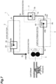
- a microfluidic device 1 according to another embodiment includes a lysis section 2, a separation section 3, a complex forming section 4, and a detection section 5 provided in a microchannel ( FIG. 7 ).
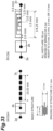
- FIGS. 7 and 8 components denoted by reference numerals not shown in FIGS. 7 and 8 are shown in FIGS. 22 and 23 which illustrate a part of Example 8 in the microfluidic device 1 shown in FIG. 7 in detail.
- a microchannel is provided, a part of the microchannel is provided with the lysis section 2, the separation section 3, the complex forming section 4, and the detection section 5, and a sample is introduced from an inlet connected to the lysis section, that is, a sample receiving inlet 2a (inlet 1), flows to a bacteriolytic agent receiving inlet 2b (inlet 2), and passes through a channel for holding a bacteriolytic agent for lysing microorganisms provided in the lysis section 2, whereby the microorganisms are lysed while passing through the channel together with the bacteriolytic agent.
- the obtained microbial lysate (lysate solution) exits from a lysate solution discharging outlet 2c, enters the separation section 3 from the inlet 3a of the separation section, and is separated into a nucleic acid and other substances (cell membrane debris, impurities such as proteins; Waste) by a separation means provided in the separation section 3, and the nucleic acid further flows to the complex forming section 4 from an inlet of the complex forming section, that is, a first result receiving inlet 4a (inlet 3).
- the nucleic acid is formed into a protein-nucleic acid complex by passing through a channel holding a substance capable of forming a protein-nucleic acid complex (also referred to as a "complex forming substance") provided in the complex forming section 4, and finally flows to the detection section 5, and the presence or absence of a specific nucleic acid is detected.
- a channel holding a substance capable of forming a protein-nucleic acid complex also referred to as a "complex forming substance”
- the channel the channels from 2a to 2c
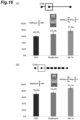
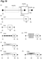
- the channel (the channels from 4a to 4c) for holding the complex forming substance in the complex forming section 4 may have the same channel structures or different channel structures, and may be, for example, Channel 6 shown in (a) of FIG. 1 or have various structures shown in FIGS. 10 and 19 .
- a material of the microfluidic device main body is not particularly limited, and examples thereof may include a plastic resin such as polydimethylsiloxane (PDMS), but are not limited thereto.
- a shape of the microfluidic device is also not limited, and a size thereof may be a normal size as a microfluidic device, and is not particularly limited.
- a diameter of the microchannel connecting the lysis section, the separation section, the complex forming section, and the detection section is also not particularly limited, and may be, for example, 20 ⁇ m to 15 mm, and is preferably 100 ⁇ m to 0.5 mm.
- the lysis section 2 performs a treatment of dissolving microorganisms contained in a sample by a bacteriolytic agent. By this treatment, microorganisms are lysed, and a lysate solution in which nucleic acids contained in microbial cells are dissolved can be obtained.
- the lysis time in the lysis section may be any time as long as the microorganisms are lysed, and may be, for example, 1 minute to 8 hours, and is preferably 5 minutes to 30 minutes.
- the lysis section 2 has the sample receiving inlet 2a (inlet 1), the bacteriolytic agent receiving inlet 2b (inlet 2), and the lysate solution discharging outlet 2c. Further, the lysis section 2 has a lysis channel 2S connecting the inlets 2a and 2b and the outlet 2c.
- the lysis channel 2S includes a first lysis channel portion 21, a second lysis channel portion 22, a lysis branch channel portion 23, and a lysis mixing channel portion 24.
- the first lysis channel portion 21 is a channel from the inlet 2a to a lysis branch part 23a.
- the lysis branch part 23a is a portion where the sample provided from the first lysis channel portion 21 is distributed and provided to the lysis branch channel portion 23.
- the second lysis channel portion 22 is a channel from the inlet 2b to a lysis confluence part 23b.
- the lysis branch channel portion 23 extends along an outer peripheral side of a rectangular region in plan view.
- the lysis branch channel portion 23 surrounds the inlet 2b and the second lysis channel portion 22.
- the above-described lysis branch part 23a may be defined as a part of the lysis branch channel portion 23.
- the lysis confluence part 23b is set on a side opposite to one side of the lysis branch channel portion 23 including the lysis branch part 23a.
- An end portion of the lysis mixing channel portion 24 and an end portion of the second lysis channel portion 22 are connected to the lysis confluence part 23b.
- the sample provided from the lysis branch channel portion 23 and the bacteriolytic agent provided from the second lysis channel portion 22 are joined, and the joined material is provided to the lysis mixing channel portion 24. That is, the end portions of the lysis branch channel portion 23, the second lysis channel portion 22, and the lysis mixing channel portion 24 are connected to the lysis confluence part 23b.
- the lysis mixing channel portion 24 is a portion for mixing and lysing the sample coming from the lysis branch channel portion 23 and the bacteriolytic agent coming from the inlet 2b.
- a lysis rate increases, whereby the detection accuracy also increases.
- the design of the channel 2S of the lysis section 2 is not particularly limited, but it is possible to increase the lysis rate of a channel by designing the two liquids, the bacteriolytic agent and the sample (for example, a bacterial suspension) to be actively mixed without forming a laminar flow, for example, by disposing protrusions/obstacles in the lysis mixing channel portion 24, extending the lysis mixing channel portion 24 as much as possible, mixing fine particles with a mixed liquid of the bacteriolytic agent and the sample, increasing a channel width ratio immediately before the two liquids meet, that is, the width ratio of a confluence channel in the lysis confluence part 23b, and the like.
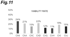
- the lysis rate in the lysis section 2 may be 50% or higher (viability rate is lower than 50%), 60% or higher (viability rate is lower than 40%), 70% or higher (viability rate is lower than 30%), 80% or higher (viability rate is lower than 20%), or 90% or higher (viability rate is lower than 10%), and the viability rate can be measured, for example, by a method shown in Examples.
- the degree of lysis can also be calculated (defined) by a nucleic acid recovery rate.
- the nucleic acid recovery rate can be measured, for example, by a method described in Examples.
- the lysis mixing channel portion 24 may be configured to change the flow state (pressure or speed) in the channel.
- a configuration in which a portion having a large channel area and a portion having a small channel area are alternately arranged, as shown in FIGS. 10(c), 10(d), and 10(f) .
- examples of the configuration for changing the flow state (pressure or speed) include a configuration for changing a flow direction ( FIG. 10(e) or 10(h) ) or a configuration including a branch part ( FIG. 10(g) ).
- the width of the lysis channel 2S may be the same as a whole, and the width of the channel may be changed in order to increase the lysis rate.
- the width of the channel 2S is not particularly limited, and may be, for example, 10 ⁇ m to 1000 ⁇ m, 50 ⁇ m to 500 ⁇ m, 50 ⁇ m to 200 ⁇ m, or 100 ⁇ m to 200 ⁇ m.
- the length of the lysis channel 2S is not particularly limited, and the shorter the length of the portion excluding the lysis mixing channel portion 24, the smaller the loss of the sample and the higher the detection accuracy.
- the lysis mixing channel portion 24 may have a length that allows the bacteriolytic agent and the sample to be sufficiently mixed, and may be, for example, 1 mm or more, 3 mm or more, 5 mm or more, 7 mm or more, or 10 mm or more.
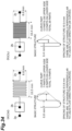
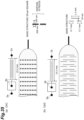
- the length of the lysis mixing channel portion 24 is too long, sample loss occurs, and therefore the length may be 500 mm or less, 400 mm or less, 300 mm or less, 200 mm or less, 100 mm or less, or 50 mm or less. Specific examples thereof include the width and the length illustrated in FIGS. 32 to 35 .
- the separation section 3 receives a lysate solution from the lysis section 2.
- the separation section 3 separates nucleic acid and impurities contained in the lysate solution.
- the separation section 3 may separate and remove impurities from the lysate solution.
- the separation section 3 provides a result (liquid containing a nucleic acid) obtained by separating and removing impurities from the lysate solution to the complex forming section 4 provided on a downstream side.
- the separation means in the separation section 3 is not particularly limited as long as it is a means capable of separating a nucleic acid and a substance other than the nucleic acid (non-nucleic acid substances, sometimes referred to herein as "impurity"), and examples thereof include a separation means using molecular size, a separation means using centrifugation, or a separation means using hydraulic filtration, and among them, a separation means using hydraulic filtration is preferable.
- the size of a cell or a substance to be selected can be adjusted as desired by designing a channel by regarding a microchannel structure as an analog of a resistance circuit such as an electric circuit.
- morphological information of the microorganisms can be obtained from the degree of separation in the channel.
- a plurality of secondary channels capable of drawing a constant flow rate are designed on both sides of a main channel which is the main.
- the cells and fine particles flowing through the main channel are gradually pressed against the wall of the main channel.
- the amount to be drawn into the secondary channel is determined, the water flowing through each of the main channel and the secondary channel is calculated as the width ratio of the main channel.
- microorganisms whose membranes have been damaged by a bacteriolytic agent are caused to flow into the main channel because of relatively large size thereof, whereas small molecules such as nucleic acids contained in the microorganisms are caused to flow into the secondary channel ( Masumi Yamada, Minoru Seki, Hydrodynamic filtration for on-chip particle concentration and classification utilizing microfluidics, Lab on a Chip, 2005, 5.11: 1233-1239 .).
- the nucleic acid flowing into the secondary channel is used as a subject to be measured.
- the separation section 3 of one embodiment includes an inlet 3a, an impurity recovery port 3b, an outlet 3c, and a separation unit 30.
- the separation unit 30 to which the lysate solution has been provided from the inlet 3a discharges the first result containing a nucleic acid from the outlet 3c and discharges a second result containing impurities from the impurity recovery port 3b.
- the second result contains impurities having large molecular sizes and may also contain a nucleic acid.
- the first result contains a highly pure nucleic acid and may contain a small amount of impurities, but it is preferable that the first result does not contain impurities.
- the nucleic acid recovery rate of the separation section 3 can be defined as a ratio of the amount of nucleic acid in the first result recovered from the outlet 3c to the amount of nucleic acid in the lysate solution charged into the inlet 3a (nucleic acid recovery rate), and the nucleic acid recovery rate of the separation section 3 may be 50% or higher, 60% or higher, 70% or higher, 80% or higher, or 90% or higher, and the nucleic acid recovery rate can be measured, for example, by a method shown in Examples.
- the separation section 3 includes a first separation channel portion 31, a second separation channel portion 32, and a separation branch channel portion 33.
- the first separation channel portion 31 connects the inlet 3a to the separation unit 30.
- a position at which the first separation channel portion 31 is connected is substantially the center in an extending direction of the separation unit 30.
- the inlet 3a does not need to be a physical component.
- the inlet 3a is a portion defined as a portion for receiving the lysate solution.
- the outlet 2c connected to the inlet 3a is a portion defined as a portion for discharging the lysate solution to the inlet 3a, and does not need to be a physical component, like the inlet 3a.
- the first separation channel portion 31 may include a first small diameter channel part 311, a large diameter channel part 312, and a second small diameter channel part 313.
- a diameter of the large diameter channel part 312 may be about 5 times larger than that of the first small diameter channel part 311.
- the first small diameter channel part 311 is disposed on an inlet 3a side
- the second small diameter channel part 313 is disposed on an outlet 3c side. That is, the second small diameter channel part 313 is connected to the separation unit 30.
- the large diameter channel part 312 is disposed between the first small diameter channel part 311 and the second small diameter channel part 313.
- the second separation channel portion 32 connects the output of separation unit 30 to outlet 3c.
- a position at which the second separation channel portion 32 is connected is substantially the center in the extending direction of the separation unit 30. That is, the first separation channel portion 31 and the second separation channel portion 32 may be arranged in a straight line on a certain imaginary line.
- the second result containing impurities is discharged to the impurity recovery port 3b.
- the impurity recovery port 3b includes a chamber having a volume capable of pooling the second result.
- FIG. 23 is an enlarged view of an example of the second separation channel portion 32.
- the second separation channel portion 32 includes a small diameter channel part 321, a first large diameter channel part 322, and a second large diameter channel part 323.
- An input end of the small diameter channel part 321 is connected to the separation unit 30.
- An output end of the second large diameter channel part 323 is connected to the impurity recovery port 3b.
- the first large diameter channel part 322 is disposed between the small diameter channel part 321 and the second large diameter channel part 323.
- a channel diameter of the first large diameter channel part 322 is larger than a channel diameter of the small diameter channel part 321 but smaller than a channel diameter of the second large diameter channel part 323.
- a diameter of the small diameter channel part 321 may be 20 ⁇ m
- a diameter of the first large diameter channel part 322 may be 25 ⁇ m
- a diameter of the second large diameter channel part 323 may be 500 ⁇ m.
- the length of the small diameter channel part 321 is longer than the length of the first large diameter channel part 322.
- the length of the small diameter channel part 321 is 1 cm
- the length of the first large diameter channel part 322 is 3.9 mm.
- the separation branch channel portion 33 connects the first part 30a that outputs the first result from the separation unit 30 and the second part 30b that outputs the first result, to the outlet 3c.
- the separation branch channel portion 33 has a U shape in plan view.
- the separation branch channel portion 33 includes the outlet 3c which is a confluence part connected to an end of the inlet 4a of the complex forming section.
- the outlet 3c may be disposed substantially at the center of one side of the separation branch channel portion 33.
- the outlet 3c is connected to the complex forming section 4.
- the outlet 3c is connected to a complex branch channel portion 43 ( FIG. 19(a) ).
- the separation branch channel portion 33 can also serve as the complex branch channel portion 43 that is a part of a complex channel 4S which will be described later.
- a first complex channel portion 41, a second complex channel portion 42, and the complex branch channel portion 43 can be omitted, and the outlet 3c is connected to a complex mixing channel portion 44 ( FIG. 22 ).
- 3c in FIG. 22 may be used as the outlet 3c of the separation section 3
- 30a and 30b in FIG. 2 may be used as the outlet 3c of the separation section 3 ( FIG. 1(b) ).
- the separation branch channel portion 33 in FIG. 22 can be used as the complex branch channel portion 43
- the outlet 3c in FIG. 22 can be used as 43b.
- the complex forming section 4 reacts the first result with a complex forming substance to form a complex.
- a microchannel holding a specific nucleic acid in the nucleic acid (nucleic acid derived from microorganisms) in the first result separated in the separation section 3 and a substance capable of forming a protein-nucleic acid complex (complex forming substance) is provided.
- the complex forming substance examples include CRISPR-dCas9 to which sgRNA specific to the specific nucleic acid is bound, and a protein marker that specifically binds to the specific nucleic acid.
- the specific nucleic acid (in the present specification, may be referred to as a "target nucleic acid") is preferably a gene or a part thereof specific to the microorganism species or the microorganism genus, which can specify the microorganism species or the microorganism genus.
- the target nucleic acid may be a lecithinase gene or a cereulide synthesis gene, or a part thereof.
- the time for forming the complex in the complex forming section 4 is not particularly limited, and may be, for example, 1 minute to 8 hours, and is preferably 5 minutes to 30 minutes.
- a channel design of the complex forming section is not particularly limited, but it is possible to increase the complex formation rate by designing the two liquids, a solution of the bacteriolytic agent and a solution of the complex forming substance to be actively mixed without forming a laminar flow as described above. That is, the complex forming section may have the above-described configuration that changes the flow state (pressure or speed).
- the complex formation rate may be 50% or higher, 60% or higher, 70% or higher, 80% or higher, or 90% or higher, and the complex formation rate can be measured, for example, by a method shown in Examples.
- the target nucleic acid and CRISPR-dCas9 to which sgRNA specific to the target nucleic acid is bound can form a complex by Watson-Crick base pair DNA-RNA interaction.
- labeling may be performed (for example, Patent Literature 3).
- the length of the sgRNA is not particularly limited, and is preferably 20 residues or more.
- the sgRNA may be a single molecule, and may be, for example, two or more molecules such as a complex of CRISPR RNA (crRNA) and trans-activating CRISPR RNA (tracrRNA), which are homing devices originally possessed by bacteria and archaea.
- Examples of the complex include a complex of Cas9 and sgRNA in which nuclease and nickase activities completely disappear due to introduction of mutation into D10A and H840A, deletion of an active site, or the like, and a complex of Cas9 and tracrRNA or crRNA.
- Examples of the Cas protein include Cas9 classified into the type II CRISPR/Cas system, and also include a crRNA-Cascade-Cas3 complex, a crRNA-Csm (III-A) or a Cmr (III-B) complex of the type I or type III CRISPR-Cas system, and a Cas12f (Cpf1)-crRNA complex of the type V CRISPR-Cas system.
- examples thereof include a crRNA-Csf2-Cas11 complex of type IV CRISPR-Cas system.
- examples thereof include a crRNA-Cas13 of the type VI CRISPR-Cas system targeting RNA sequences.
- the origin of the Cas protein described above is not particularly limited.
- the protein marker that specifically binds to the target nucleic acid is preferably one that can bind to the target nucleic acid by a secondary structure of a protein such as a helix recognizing a nucleic acid sequence.
- a protein marker include Transcription activator-like effector (TALE), Zinc-Finger (ZF), and Pentatricopeptide repeat (PPR) protein.
- the complex forming section 4 may have a structure similar to that of the lysis section 2 ( FIGS. 1 and 19 ).
- the complex forming section 4 of one embodiment has a first result receiving inlet 4a, a complex forming substance receiving inlet 4b (inlet 3), and a complex discharging outlet 4c. Further, the complex forming section 4 has the complex channel 4S connecting the inlets 4a and 4b and the outlet 4c.
- the complex channel 4S includes a first complex channel portion 41, a second complex channel portion 42, a complex branch channel portion 43, and a complex mixing channel portion 44.
- the first complex channel portion 41 is a channel from the inlet 4a to a complex branch part 43a.
- the complex branch part 43a is a portion where the first result provided from the first complex channel portion 41 is distributed and provided to the complex branch channel portion 43.
- the second complex channel portion 42 is a channel from the inlet 4b to a complex confluence part 43b.
- the complex branch channel portion 43 extends along an outer peripheral side of the rectangular region in plan view.
- the complex branch channel portion 43 surrounds the inlet 4b and the second complex channel portion 42.
- the above-described complex branch part 43a may be defined as a part of the complex branch channel portion 43.
- the complex confluence part 43b is set on a side opposite to one side of the complex branch channel portion 43 including the complex branch part 43a.
- An end of the complex mixing channel portion 44 and an end of the second complex channel portion 42 are connected to the complex confluence part 43b.
- the sample provided from the complex branch channel portion 43 and the complex forming substance provided from the second complex channel portion 42 are joined, and the joined material is provided to the complex mixing channel portion 44. That is, the end portions of the complex branch channel portion 43, the second complex channel portion 42, and the complex mixing channel portion 44 are connected to the complex confluence part 43b.
- the complex mixing channel portion 44 is a portion for mixing the first result coming from the complex branch channel portion 43 and the complex forming substance coming from the inlet 4b to form a complex.
- the complex formation rate increases, whereby the detection accuracy also increases.
- the design of the complex channel 4S of the complex forming section 4 is not particularly limited, and may be the same as the design of the channel 2S of the lysis section 2 ( FIGS. 10 and 19 ).
- the complex formation rate in the complex forming section 4 may be 40% or higher, 50% or higher, 60% or higher, 70% or higher, 80% or higher, or 90% or higher, and the complex formation rate can be measured, for example, by a method shown in Examples.
- the complex mixing channel portion 44 may be configured to change the flow state (pressure or speed) in the channel.
- Examples of such a configuration include a configuration in which a portion having a large channel area and a portion having a small channel area are alternately arranged, as shown in FIG. 19(d) .
- examples of the configuration for changing the flow state (pressure or speed) include a configuration for changing a flow direction ( FIG. 19(e) ) or a configuration including a branch part ( FIGS. 10(f), 10(g), and 10(h) ).
- the width of the complex channel 4S may be the same as a whole, and the width of the channel may be changed in order to increase the complex formation rate.
- the width of the complex channel 4S is not particularly limited, and may be, for example, 10 ⁇ m to 1000 ⁇ m, 50 ⁇ m to 500 ⁇ m, 50 ⁇ m to 200 ⁇ m, or 100 ⁇ m to 200 ⁇ m.
- the length of the complex channel 4S is not particularly limited, and the shorter the length of the portion excluding the complex mixing channel portion 44, the smaller the loss of the sample and the higher the detection accuracy.
- the complex mixing channel portion 44 may have a length that allows the first result and the complex forming substance to be sufficiently mixed, and may be, for example, 1 mm or more, 3 mm or more, 5 mm or more, 7 mm or more, or 10 mm or more.
- the length of the complex mixing channel portion 44 when the length of the complex mixing channel portion 44 is too long, sample loss occurs, and therefore the length may be 500 mm or less, 400 mm or less, 300 mm or less, 200 mm or less, 100 mm or less, or 50 mm or less. Specific examples thereof include the width and the length illustrated in FIGS. 32 to 35 .
- the detection section 5 including a means for detecting the complex is not particularly limited, and for example, preferably includes a means for electrochemically or optically detecting the complex, and particularly preferably detects the complex using nanopores.
- a means for detecting the nucleic acid by real-time PCR or an immunological method may be provided.
- nanopores detection can be performed by, for example, a mechanism as described in Non Patent Literature 1.
- the nanopores are obtained by embedding a transmembrane protein on a lipid bilayer membrane, and the transmembrane protein has openings (nanopores).
- a voltage is applied to both sides of the lipid bilayer membrane, a current flows.
- a current value in the nanopore temporarily decreases (blocking), and when the complex passes through or kicked out of the nanopore, the current value recovers, so that the presence of the complex can be detected.
- the nucleic acid since the size thereof is small, the time during which the nucleic acid stays in the nanopore is short, or the change in the current value when the nucleic acid passes through the nanopore is small (small blocking), so that the nucleic acid can be distinguished from the complex.
- CRISPR-dCas9 not bound to a nucleic acid, it is positively charged under the measurement pH condition and does not enter the inside of the nanopore ( FIG. 9 ).
- Non Patent Literature 1 The technique used in Non Patent Literature 1 is called solid state nanopore (solid nanopore).
- the solid nanopore is formed by irradiating a solid material such as silicon nitride or graphene with an electron beam by a semiconductor microfabrication technique.
- Large scale devices are required to produce solid nanopores, and there remains a problem in the cost of pore production and reliability of pore diameter.
- the nanopore used in the present invention is called a biological nanopore using a membrane protein. Since the biological nanopore is formed by spontaneous association and insertion of a membrane protein into the membrane, pore formation is easy, and a pore diameter can be adjusted by one molecular unit of protein by performing protein engineering modification. Therefore, a pore having a diameter corresponding to the size of the nucleic acid-protein complex as a target can be designed and constructed, and more sensitive detection becomes possible.
- the method for adjusting the pore diameter is not particularly limited, but for example, in the case of a pore of a type in which a plurality of membrane protein monomers associate to form a pore, the number of monomers forming the pore can be controlled by eliminating or imparting a structural steric hindrance when the monomers interact with each other, and the pore diameter can be increased or decreased.
- the number of monomers forming the pore can be controlled by rigidizing the main chain of the monomer by amino acid mutation or reducing molecular fluctuation of the monomer by an experiment at a low temperature.
- pores having a predetermined diameter can be formed by creating pores of a desired diameter with DNA or the like and recruiting the membrane protein monomers thereof.
- pores having a predetermined diameter can be formed by introducing a random mutation of amino acids into a monomer and selecting a molecule that forms a pore having a predetermined diameter.
- the monomer is not limited to a pure membrane protein, and for example, a pore modified with a protein marker can be produced by binding and co-expressing the monomer and the protein marker.
- the target nucleic acid can be detected by a decrease in the current value due to the binding between the target nucleic acid and the protein marker.
- a protein marker having an optimum size for the pore whose diameter is adjusted more sensitive detection can be achieved.
- the size of the nanopore is not particularly limited as long as it is adjusted in accordance with the size of the complex, and may be, for example, 1 to 100 nm, and is preferably 15 nm to 40 nm.
- optical detection examples include fluorescence detection and absorption detection, and also include spectroscopic detection such as infrared spectroscopy, near-infrared spectroscopy, and Raman spectroscopy.
- the microfluidic device 1 may be, for example, an integrated device in which a lysis section and a separation section are provided on a device substrate made of glass or a resin material, or may be an integrated device in which a lysis section, a separation section, and a complex forming section are provided, or an integrated device in which a lysis section, a separation section, a complex forming section, and a detection section are provided.
- the microfluidic device 1 may include an additional device connected to the device substrate in order to perform the functions thereof.
- the microfluidic device 1 may include a pump and a tube connected to the device substrate (specifically, an inlet and/or an outlet of each functional unit).
- the microfluidic device 1 of one embodiment includes the lysis section 2, the separation section 3 communicating with the lysis section, the complex forming section 4 communicating with the separation section 3, and the detection section 5 communicating with the complex forming section 4.
- the detection section 5 includes a means for detecting the complex formed in the complex forming section 4, for example, a means for electrochemically or optically detecting the complex, particularly a detection means using a nanopore.
- a microfluidic device 1 includes a lysis section 2, a separation section 3 communicating with the lysis section, and a detection section 5 communicating with the separation section 3. That is, the complex forming section may not be provided.
- the detection section 5 includes a means for detecting the nucleic acid obtained in the separation section 3, for example, a detection means using real-time PCR or an immunological method.
- a method for detecting microorganisms in a sample is a method using the microfluidic device of the present invention.
- the microfluidic device used be a device which has been integrated (integrated device).
- the detection method of one embodiment includes a lysis step of lysing microorganisms in a sample in the lysis section; and a separation step of separating out a nucleic acid from a lysate of microorganisms, in the separation section.
- the detection method may further include a complex forming step of forming a protein-nucleic acid complex from the nucleic acid separated in the separation section in the complex forming section, and may further include a detection step of detecting the protein-nucleic acid complex formed in the complex forming section, in the detection section.
- the method for detecting microorganisms in a sample of one embodiment uses the microfluidic device, and includes:
- the detection method includes: a lysis step of lysing microorganisms in a sample in the lysis section; a separation step of separating out a nucleic acid from a lysate of microorganisms obtained in the lysis section, in the separation section; and a detection step of detecting the nucleic acid separated in the separation section, in the detection section.
- Design software Illustrator (manufactured by Adobe, Inc.) was used to design a channel.
- the designed channel (Channel 6 and Channel 1) is shown in FIG. 1 .
- the Channel 6 has a width of 100 ⁇ m, and the detailed structure of the channel is the same as that in FIG. 32(a) .
- a blueprint was sent to Tokyo Process Service (TOPRO) Co., Ltd. to request photomask production.
- the photomask was created such that a size was 4 inches, light-shielding/transmitting parts: a white part was light-shielding and a black part was transmitting, and a film surface: a printed surface appeared as designed when viewed from a glass side.
- a 4 inch Si wafer was placed in a plasma generator (Yamato Scientific Co., Ltd., PR-200) with a mirror surface facing upward, and treated at 100 W for 30 seconds.
- the plasma-treated wafer was set in a central portion of a spin coater, and SU-8 resist (SU-8 3025 for Channel 1 and SU-8 3050 for Channel 6) manufactured by Nippon Kayaku Co., Ltd. was added dropwise to the central portion of the wafer with a dropper whose tip was cut.
- the resist was spread over the entire surface of the wafer using a dropper, and then a spin coater was rotated to uniformly apply the resist.
- the number of revolutions was 500 rpm ⁇ 30 seconds, 500 ⁇ 4000 rpm (10 seconds), and 4000 rpm ⁇ 30 seconds. After incubation at 95°C for 30 minutes or more, the temperature was lowered to 65°C to solidify the resist. After the temperature was returned to room temperature, a film thickness was measured.
- the mask was set on the Si wafer so that a Cr surface was in contact with the wafer, and exposed to light with a UV exposure device (manufactured by Nanotech Co., Ltd.) at 150 W for 5 seconds. After the exposure, the film was incubated again at 95°C for 30 minutes.
- a UV exposure device manufactured by Nanotech Co., Ltd.
- the SU-8 Developer was placed in a petri dish, and the wafer was immersed and developed for 2 or 3 minutes while a liquid level was appropriately shaken.
- the wafer was lifted from the petri dish with tweezers, and a developer was poured on both front and back surfaces while being tilted.
- a compressor was applied on a Kimtowel to blow off a solution and let it dry well.
- a 1% solution of dimethyloctadecylchlorosilane solvent: toluene
- was prepared as a release treatment liquid and the solution was placed in a petri dish, the wafer was immersed, and left for about 5 minutes.
- the wafer was washed with toluene, and then dried well by blowing off the solution with a compressor.
- the silicone potting material SILPOT TM 184 (Dow Toray) Erastomer Base and Erastomer Curing Agent were weighed at a ratio of 10:1, and mixed. An adjustment liquid was poured onto the prepared base, placed in a desiccator, degassed, and then incubated at 85°C for 35 minutes. After the temperature was returned to room temperature, the periphery of the channel was cut out and further trimmed, then a hole was made with a biopsy trephine or a leather punch (2.0 mm), and the core was removed with tweezers.
- the cored PDMS and slide glass were placed in a plasma generator with the surfaces to be bonded facing up, treated at 100 W for 10 seconds, then the slide glass was taken out on the petri dish with tweezers, and the PDMS was bonded to the slide glass.
- a silicone tube having an appropriate diameter was inserted into an inlet and an outlet of the channel and subjected to evaluation.
- Bacillus cereus JCM17690 strain (cereulide synthase gene-carrier strain) and NBRC3836 strain (cereulide synthase gene-non-carrier strain) were used.
- the glycerol stocks were streaked onto standard agar media and plated overnight at 30°C under aerobic conditions.
- the cells were planted in tryptic soy broth liquid medium and cultured overnight at 30°C with shaking.
- the number of bacteria was estimated by colony count, and a dilution series of the culture solution was prepared with peptone added saline.
- the channel of Channel 6 was used for verification.
- the bacteriolytic agent and the microbial suspension (Bacillus cereus suspension suspended in 0.9% saline so as to have a bacterial concentration of 10 7 cfu/ml) were each fed at 3.0 ⁇ l/min or 4.0 ⁇ l/min using a syringe pump.
- Channel 6 as a lysis section (lysis channel) and Channel 1 as a separation section (separation channel) were used.
- SDS was used as a bacteriolytic agent.
- each of the bacteriolytic agents and the microbial suspension (Bacillus cereus suspension suspended in 0.9% saline so as to have a bacterial concentration of 10 7 cfu/ml) were each delivered at 8.0 ⁇ l/min using a syringe pump to the channel of Channel 6. Thereafter, it was connected to an inlet of Channel 1 with a 1 mm diameter tube, and a sample was collected from the secondary channel outlet (nucleic acid recovery port).
- the lysis rate was calculated by quantitative PCR.
- primers, enzymes, and the like those attached to the CycleavePCRtm Bacillus cereus (CRS gene) Detection Kit (Takara Bio Inc.) were used.
- the lysate solution recovered from the secondary channel outlet was purified by QIAquick Gel Extraction Kit (manufactured by Qiagen) and verified under the following conditions. Hold (initial denaturation): 95°C, 10 s ⁇ 3 step PCR: 45 cycles (95°C, 5 s ⁇ 55°C, 10 s ⁇ 72°C, 20 seconds).
- a Ct value of the sample that was left standing overnight after addition of SDS to a bacterial fluid at the same concentration in vitro was regarded as a "100% lysed" control, and the lysis rate of the sample lysed in the channel under each SDS concentration condition was evaluated. The results are shown in FIG. 3 . While 0.2% SDS had the highest lysis rate of 60%, 0.1% SDS and 0.05% SDS had a lysis rate of 20% or lower.
- SDS used during lysis may inhibit the formation of a complex between dCas9/sgRNA and a target nucleic acid. Therefore, whether or not the complex can be formed at the SDS concentration contained in the sample passing through Channel 6 and Channel 1 was verified in vitro.
- the SDS concentration after passing through Channel 6 and Channel 1 was calculated to be about 0.0225%.
- the mixed liquid was electrophoresed at 4°C and 30 mA for 130 minutes using Super Sep-Ace 10% to 20% gel (FUJIFILM Wako Pure Chemical Corporation) and Tris-glycine buffer (pH 9.5). After electrophoresis, the cells were immersed in a 1 ⁇ GelRed solution and stained for 20 minutes. After staining, images were taken with a UV imager.
- a mixed solution of 6 ⁇ l of 0.15 ⁇ g/ ⁇ l dCas9 and 3 ⁇ l of 2.3 ⁇ M sgRNA, 2 ⁇ l of 10 ⁇ H buffer, and 4.5 ⁇ l of MilliQ (trademark) water were added to 4.5 ⁇ l of a sample which was lysed in Channel 6, separated in Channel 1, and collected from the outlet (nucleic acid recovery port) of Channel 1, and the mixture was incubated at 37°C for 60 minutes.
- 4.7 ⁇ l of a buffer 140 mM KCl, 10 mM DTT, and 10mM MOPS (pH 7) was added to pores on a positive electrode side of a microdevice capable of reconstituting an artificial lipid bilayer membrane by a liquid contact method.
- 4.7 ⁇ l of the complex solution described above was added to a negative electrode side.
- PICO2 manufactured by Tesla
- lipid bilayer membrane (membrane capacity 65 to 70 pF) suitable for membrane protein insertion was formed using a trace rod. Pore formation due to association of membrane proteins on the lipid bilayer membrane and entry of molecules into the pore were detected by a change in current value. Analysis was performed by Clampex (free software), and blocking conductance calculated from the current value when the current in the pore was inhibited and the time (Duration time) when the current was inhibited were calculated.
- FIG. 6(D) illustrates a result of plotting the detected Blocking conductance and Duration time.
- a signal with a long Duration time which was not observed when only the SLO ( FIG. 6(A) ), the SLO and the cesA plasmid ( FIG. 6(B) ), or the SLO and dCas9/sgRNA ( FIG. 6(C) ) were added, was detected only when the SLO and the lysate solution recovered from the microchannel outlet were added. From this result, it was suggested that a signal with a long Duration time was observed only when the complex of the dCas9/sgRNA and the target cesA plasmid entered the inside of the pore.
- the secondary channel outlet of Channel 1 and the inlet of Channel 6 were connected by a 1 mm diameter tube. From the other inlet, a solution in which 0.12 ⁇ g/ml dCas9, 2.7 ⁇ M sgRNA, and 110 ⁇ H buffer were mixed flowed in at 8.0 ⁇ l/min using a syringe pump. Samples were taken from the outlet and subjected to current inhibition evaluation experiments.
- the nucleic acid-protein complex formed in the microchannel was subjected to the evaluation of the current value by PICO2.
- the results are shown in FIG. 6(E) .
- a signal with a long Duration time was detected. From this result, it was suggested that the complex formed in the channel entered the inside of the pore and was detected by a change in the current value.
- Channel A In addition to Channel 6 used in Example 1, a plurality of channels were designed so that the mixing of the bacteriolytic agent and the microorganism in the channel proceeded more efficiently, and among them, Channel A, C, D, G, H, I, and J channels were used for evaluation ( FIG. 10 ). Details of the structure of these Channels are shown in FIGS. 32 to 35 .
- the channel lengths (lengths from 2b to 2c) of Channel 6 and Channel A were both 2.5 cm, and the width (diameter) of the channel was 100 ⁇ m unless otherwise specified.
- the degrees of lysis of various kinds of bacteriolytic agents were compared. Channel 6 of Example 1 was consistently used for evaluation.
- the bacteriolytic agent used for the evaluation is shown in FIG. 12 .
- Various bacteriolytic agents and a microbial suspension (cell count concentration: 10 9 cfu/ml) were each fed at 5.0 ⁇ l/min using a syringe pump, and a sample was collected from the outlet (2c).
- the addition concentrations were all prepared so that the final concentration was the critical micelle concentration (CMC).
- CMC critical micelle concentration
- the recovered liquid was diluted 10 4 times with peptone water, and seeded on a 100 ⁇ l plate, and cultured overnight at 30°C.
- the number of bacteria before flowing into the channel was compared with the number of bacteria counted in the recovered liquid, and the viability rate was calculated.
- the degrees of lysis were compared in more detail by comparing the nucleic acid recovery rate by quantitative PCR.
- primers, enzymes, and the like those attached to the CycleavePCR TM Bacillus cereus (CRS gene) Detection Kit (Takara Bio Inc.) were used.
- the recovered liquid was purified by QIAquick Gel Extraction Kit (manufactured by Qiagen) and verified under the following conditions. Hold (initial denaturation): 95°C, 10 s ⁇ 3 step PCR: 45 cycles (95°C, 5 s ⁇ 55°C, 10 s ⁇ 72°C, 20 seconds).
- a Ct value of the sample that was left standing overnight after addition of the bacteriolytic agent to a bacterial fluid at the same concentration in vitro was regarded as a "100% lysed" control, and the lysis rate of the sample lysed in the channel with each bacteriolytic agent was evaluated.
- a commercially available lysis reagent BugBuster (trademark) Protein Extraction Reagent (Merck) which is considered to exhibit a high lytic effect, was used for verification.
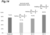
- Sulfobetaine-8 (SB-8) and sulfobetaine-14 (SB-14) in which a carbon chain of the sulfobetaine was modified were added to the comparative subjects, and the nucleic acid recovery rates were compared.
- Channel 6 and Channel H of Example 1 were used as a channel structure, and SDS, BugBuster, and SB-14 were used as a bacteriolytic agent.
- Channel H was used, and three kinds of SDS, generally used benzalkonium chloride (BC), and SB-14 were used as the bacteriolytic agent.
- SDS generally used benzalkonium chloride
- SB-14 was used as the bacteriolytic agent.
- food poisoning bacteria of a subject Listeria monocytogenes, Staphylococcus aureus, and Salmonella enterica were used.
- CycleavePCR TM Listeria monocytogenes (inlA gene) Detection Kit, CycleavePCR TM Staphylococcus aureus (DnaJ gene) Detection Kit, and CycleavePCR TM Salmonella Detection Kit Ver. 2.0 which were quantitative PCR kits manufactured by Takara Bio Inc. were used. Pretreatment and measurement conditions were the same as for the Bacillus cereus.
- FIG. 17 The results are shown in FIG. 17 . It was suggested that all of the four bacterial species were lysed in the channel. For each strain, Listeria monocytogens showed a similar tendency to Bacillus cereus ( FIGS. 17(A) and 17(B) ). On the other hand, in Staphylococcus aureus, SDS and SB-14 showed almost the same lysis rate ( FIG. 17(C) ), and in Salmonella enterica, SDS showed a higher lysis rate ( FIG. 17(D) ). This is considered to be due to a difference in membrane structure (Gram-positive/negative). From this result, it was suggested that the present lysis step can be applied to various food poisoning bacteria by setting an appropriate bacteriolytic agent according to the bacterial species.
- FRET fluorescence resonance energy transfer
- the complex formation of the cesA plasmid which is a nucleic acid derived from Bacillus cereus, and the protein dCas9 was evaluated. Specifically, when cesA and dCas9 are modified with different fluorescent dyes and both of them form a complex, the modified green and red fluorescent dyes come close to each other to generate FRET. A conceptual diagram is shown in FIG. 18 . Complex formation was quantitatively evaluated using the red fluorescence intensity increased by FRET as an index.
- Alexa Fluor TM 546 NHS Ester (Succinimidyl Ester, Invitrogen) was used. 1 ⁇ l of 10 mg/ml Alexa Fluor 546, 6.7 ⁇ l of 15 mg/ml dCas9, and 13.3 ⁇ l of 0.2M NaHCO 3 (pH 8.3) dissolved in DMF were mixed, and the mixture was incubated at room temperature for 1 hour for reaction. Purification was performed using an Amicon Ultra 0.5 mL centrifugal filter (Merck) to obtain a desired product.
- Amicon Ultra 0.5 mL centrifugal filter Merck
- Channel 7 was designed to have a channel length twice that of Channel 6
- Channel 5 was designed to have a channel length half that of Channel 6.
- the Channel I was applied to design the Channel I4 in which the number of branches and confluence parts was doubled. Since it was considered that there was a concern of clogging in the channel due to an increase in the number of branches and confluence parts, the channel width was designed to be twice as large from the middle.
- the channel width from 4b to the midpoint between 4b and 4c (channel central portion 4d) (4b to 4d, length 1.25 cm) was 100 ⁇ m
- the channel width from the midpoint between 4b and 4c (channel central portion 4d) to 4c (4d to 4c, length 1.25 cm) was 100 ⁇ m to 200 ⁇ m.
- Channel I2 in which the number of branches and confluence parts were equal to that of Channel I and the channel width was changed twice from the middle was also used for evaluation.
- fluorescein-modified cesA and Alexa Fluor546 modified dCas9 were added to 1 ⁇ H Buffer (manufactured by Takara) so as to have final concentrations of 0.25 ⁇ g/ml and 2.5 ⁇ g/ml, respectively.
- BSA was added so as to have a final concentration of 0.2%.
- the cesA solution and the dCas9 solution were separately fed from each of the two inlets (4a and 4b) at 5.0 ⁇ l/min using a syringe pump, and 10 ⁇ l of each sample was collected from the outlet 4c.
- the sample obtained by adding the cesA solution and the dCas9 solution in the microtube and incubating for 1 hour was regarded as a "100% complex formed" control, and the complex formation rate of a sample in which the complex was formed in the channel was evaluated in comparison with the fluorescence intensity of the sample solution.
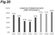
- FIG. 20 shows the results of comparing the complex formation rates in various channels.
- the Channel 5 the Channel 7, and the Channel G in which the channel length was changed from the Channel 6 of Example 1
- no improvement in the formation rate was observed.
- Channel H in which a high lytic effect was observed in the lysis step
- no remarkable improvement was observed.
- Channel I provided with a branch and a confluence part
- the complex formation rate was improved.
- the intermediate change of the channel width did not affect the complex formation, and clogging in the channel was not actually observed.
- the complex formation rate was further improved. From this result, it was suggested that the "branch and confluence" structure in the channel affected the complex formation, and among the studied Channels, Channel I4 was optimal.
- the effects of the device in which the "lysis section", the “separation section”, and the “complex forming section” are integrally connected were studied.
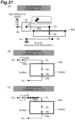
- a pretreatment integrated channel was prepared, and whether or not nucleic acid could be recovered from the outlet 4c, which is the outlet of the integrated channel, was verified by adding the microbial solution and the bacteriolytic agent from the inlet 1 (2a) and the inlet 2 (2b), respectively.
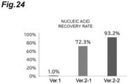
- Three types of integrated channels were used for evaluating the degree of lysis.
- the first studied integrated channel ver. 1 ( FIG. 21(A) ) was coupled without considering the resistance in the channel.
- FIGS. 22 and 23 A channel whose channel structure is appropriately designed in view of the resistance in the channel is ver. 2-1 ( FIG. 21(B) ). Further, a channel incorporating the structure of Channel H exhibiting a high lytic effect is ver. 2-2 ( FIG. 21(C) ). The detailed structure of ver. 2-1 is shown in FIGS. 22 and 23 .
- FIG. 25 shows a structure of a newly designed pretreatment integrated channel.
- the channel incorporating Channel I was set as ver. 3-1 ( FIG. 25(B) ), and the channel incorporating Channel I4 was set as ver. 3-2 ( FIG. 25(C) ).
- the complex formation rates were compared among these three kinds of pretreatment integrated channels.
- an integrated device (may be referred to herein as a "pretreatment and detection integrated channel” or simply as an “integrated channel”) that can seamlessly perform pretreatment to detection was prepared.
- a hole having a diameter of 6 mm was made in the outlet 4c of the above-described pretreatment integrated channel ver. 2-2 so that a certain amount of solution was accumulated in the detection section ( FIG. 26(A) ).
- PDMS as a material was adjusted to a thickness of 10 to 13 mm ( FIG. 26(B) ).
- Bacillus cereus (1 ⁇ 10 3 cfu/ml) from the inlet 1 Bacillus cereus (1 ⁇ 10 3 cfu/ml) from the inlet 1, a bacteriolytic agent (sulfobetaine-14) from the inlet 2, and a mixed solution of the dCas9/sgRNA complex and Streptolysin O (final concentration: 30 nM) dissolved in 1 ⁇ H buffer (manufactured by TAKARA) from the inlet 3 were caused to flow into the device at flow rates of 5.0 ⁇ l/min, 5.0 ⁇ l/min, and 4.0 ⁇ l/min, respectively. After 42 minutes, the solution in the chamber was removed, and then the inflow was started again.
- bacteriolytic agent sulfobetaine-14
- Streptolysin O final concentration: 30 nM
- DPhPC/Cholesterol 1:1 (mol/mol)
- the silver wire glass electrode was inserted into an oil layer, and a reference electrode was inserted into a water tank into which the reference electrode flowed in, and a voltage was applied at 100 mV.
- a lipid bilayer membrane was formed by moving the electrode up and down in a Z-axis direction with a hydraulic manipulator ( Shoji, K., et al., Anal.
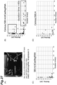
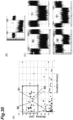
- FIGS. 27(B), 27(C), and 27(D) show the results of analyzing and plotting each signal, with a current value dropped from a current value observed in a state where the pore is opened as Blocking (pA) and a time during which the current value is maintained as Duration time. It has been revealed that, in a case where Bacillus cereus, a bacteriolytic agent, and dCas9/sgRNA flowed into the channel ( FIG. 27B ), there were some signals that were not observed in a case where the bacteriolytic agent and dCas9/sgRNA were flowed in ( FIG. 27C ) or in a case where Bacillus cereus and a bacteriolytic agent flowed in ( FIG.
- FIG. 27D a signal having 50 pA or less at a Duration time of 100 seconds or more was observed ( FIG. 27(B) ).
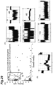
- FIG. 28(A) illustrates five signals with Blocking of 400 pA or more and a Duration time of 30 seconds or more.
- a bacteriolytic agent As for the case where Bacillus cereus, a bacteriolytic agent, and dCas9/sgRNA flowed into the channel (Signal No. 70, 73, 78, and 80), when examining the shape of the signals, a flat signal was observed as in the baseline ( FIG. 28(C) ) when the molecule entered the pore and the current value decreased.
- signal disturbance was observed after the current value dropped ( FIG. 28(B) ).
- FIG. 29(A) Similarly, also for 9 signals ( FIG. 29(A) ) having Blocking of 400 pA or more and a Duration time of 4 seconds or more and 20 seconds or less, a flat signal ( FIG. 29(C) ) was observed when Bacillus cereus, a bacteriolytic agent, and dCas9/sgRNA flowed in, and signal disturbance was observed when Bacillus cereus and a bacteriolytic agent flowed in ( FIG. 29(B) ).
- the Bacillus cereus lysate solution recovered from the membranes from the inlet 1 and the inlet 2 of the integrated device ( FIG. 27(A) ) was allowed to flow into the device at a flow rate of 8.0 ⁇ l/min. After 20 minutes, the flow rate was changed to 5.0 ⁇ l/min, and at the same time, a mixed solution of the dCas9/sgRNA complex dissolved in 1 ⁇ H buffer (manufactured by TAKARA) and Streptolysin O (final concentration: 30nM) was caused to flow from the inlet 3 at a flow rate of 4.0 ⁇ l/min. After 60 minutes, the solution in the chamber was removed, and then the inflow was started again.
- DPhPC/Cholesterol 1:1 (mol/mol)
- the silver wire glass electrode was inserted into an oil layer, and a reference electrode was inserted into a water tank into which the reference electrode flowed in, and a voltage was applied at 100 mV.
- a lipid bilayer membrane was formed by moving the electrode up and down in a Z-axis direction with a hydraulic manipulator ( Shoji, K., et al., Anal.
- FIG. 31 shows the results of analyzing and plotting each signal as Blocking (pA) and a time during which the current value is maintained as Duration time.
- pA Blocking
- FIGS. 31(A) and 31(C) show the results of analyzing and plotting each signal as Blocking (pA) and a time during which the current value is maintained as Duration time.
Landscapes
- Health & Medical Sciences (AREA)
- Life Sciences & Earth Sciences (AREA)
- Immunology (AREA)
- Chemical & Material Sciences (AREA)
- Engineering & Computer Science (AREA)
- Hematology (AREA)
- Biomedical Technology (AREA)
- Urology & Nephrology (AREA)
- Molecular Biology (AREA)
- Analytical Chemistry (AREA)
- General Health & Medical Sciences (AREA)
- Medicinal Chemistry (AREA)
- Biochemistry (AREA)
- Cell Biology (AREA)
- Microbiology (AREA)
- Biotechnology (AREA)
- Pathology (AREA)
- Food Science & Technology (AREA)
- General Physics & Mathematics (AREA)
- Physics & Mathematics (AREA)
- Chemical Kinetics & Catalysis (AREA)
- Dispersion Chemistry (AREA)
- Clinical Laboratory Science (AREA)
- Tropical Medicine & Parasitology (AREA)
- Virology (AREA)
- Measuring Or Testing Involving Enzymes Or Micro-Organisms (AREA)
Applications Claiming Priority (2)
| Application Number | Priority Date | Filing Date | Title |
|---|---|---|---|
| US202263345969P | 2022-05-26 | 2022-05-26 | |
| PCT/JP2023/019510 WO2023229010A1 (fr) | 2022-05-26 | 2023-05-25 | Procede et dispositif de detection de micro-organismes |
Publications (1)
| Publication Number | Publication Date |
|---|---|
| EP4524228A1 true EP4524228A1 (fr) | 2025-03-19 |
Family
ID=88919458
Family Applications (1)
| Application Number | Title | Priority Date | Filing Date |
|---|---|---|---|
| EP23811882.2A Pending EP4524228A1 (fr) | 2022-05-26 | 2023-05-25 | Procede et dispositif de detection de micro-organismes |
Country Status (3)
| Country | Link |
|---|---|
| EP (1) | EP4524228A1 (fr) |
| JP (1) | JPWO2023229010A1 (fr) |
| WO (1) | WO2023229010A1 (fr) |
Family Cites Families (7)
| Publication number | Priority date | Publication date | Assignee | Title |
|---|---|---|---|---|
| AU2082701A (en) * | 1999-12-09 | 2001-06-18 | Motorola, Inc. | Multilayered microfluidic devices for analyte reactions |
| JP5627886B2 (ja) * | 2006-05-16 | 2014-11-19 | フルイディウム コーポレーション | 生物学的な高速解析および高速識別のための、pcrを使用しない試料調製および検出システム |
| EP3183358B1 (fr) * | 2014-08-19 | 2020-10-07 | President and Fellows of Harvard College | Systèmes guidés par arn pour sonder et cartographier des acides nucléiques |
| GB201616590D0 (en) * | 2016-09-29 | 2016-11-16 | Oxford Nanopore Technologies Limited | Method |
| WO2019124904A1 (fr) | 2017-12-19 | 2019-06-27 | 주식회사 바이오맥스 | Puce de papier microfluidique pour la détection d'un micro-organisme, son procédé de préparation et procédé de détection de micro-organisme l'utilisant |
| JP6877804B2 (ja) | 2018-05-07 | 2021-05-26 | bitBiome株式会社 | シングルセル解析を行う方法およびそのための装置 |
| CN112501258B (zh) * | 2020-11-10 | 2023-04-18 | 清华大学深圳国际研究生院 | 用于核酸提取纯化及扩增检测的微流控芯片 |
-
2023
- 2023-05-25 EP EP23811882.2A patent/EP4524228A1/fr active Pending
- 2023-05-25 JP JP2024523344A patent/JPWO2023229010A1/ja active Pending
- 2023-05-25 WO PCT/JP2023/019510 patent/WO2023229010A1/fr not_active Ceased
Also Published As
| Publication number | Publication date |
|---|---|
| WO2023229010A1 (fr) | 2023-11-30 |
| JPWO2023229010A1 (fr) | 2023-11-30 |
Similar Documents
| Publication | Publication Date | Title |
|---|---|---|
| US11254927B2 (en) | Polynucleotide capture materials, and systems using same | |
| US7214299B2 (en) | Method for separation, identification and evaluation of microbes and cells | |
| EP2510123B2 (fr) | Lyse sélective de cellules | |
| Müller et al. | Functional single-cell analyses: flow cytometry and cell sorting of microbial populations and communities | |
| DE69802191T3 (de) | Festphasen-Nukleinsäure-Isolierung | |
| JP6523961B2 (ja) | 微生物細胞を抽出するための装置及び方法 | |
| Bao et al. | Microfluidic electroporation of tumor and blood cells: observation of nucleus expansion and implications on selective analysis and purging of circulating tumor cells | |
| US20100129878A1 (en) | Methods for nucleic acid amplification | |
| Wu et al. | An in situ exosomal miRNA sensing biochip based on multi-branched localized catalytic hairpin assembly and photonic crystals | |
| Lu et al. | Sensitive and automated detection of bacteria by CRISPR/Cas12a-assisted amplification with digital microfluidics | |
| CN111670067B (zh) | 用于从生物材料中分离细胞外囊泡的方法 | |
| US20240368579A1 (en) | Targeted nanodroplet and microbubble compositions and methods for enrichment, lysis, and extraction of microbial cells | |
| Wang et al. | Cascade filtration and droplet digital detection integrated microfluidic assay enables isolating culture-free phenotypic identification of carbapenem-resistant organisms | |
| Sum et al. | Beta-hemolytic bacteria selectively trigger liposome lysis, enabling rapid and accurate pathogen detection | |
| US20170275612A1 (en) | Apparatus and method for extracting microbial cells | |
| Wei et al. | Rapid, ultrasensitive, and visual detection of pathogens based on cation dye-triggered gold nanoparticle electrokinetic agglutination analysis | |
| EP3420099B1 (fr) | Détection de pathogènes bêta-hémolytiques | |
| EP4524228A1 (fr) | Procede et dispositif de detection de micro-organismes | |
| EP4283300A2 (fr) | Capture de micro-organisme à partir d'une solution contenant un agent antimicrobien | |
| Zahavy et al. | Application of nanoparticles for the detection and sorting of pathogenic bacteria by flow-cytometry | |
| JP2025542198A (ja) | 分析物を単離するための方法、システム、および組成物 | |
| KR101308685B1 (ko) | 막 분석 방법 | |
| WO2013117968A1 (fr) | Procédés de lyse de bactéries provenant d'un échantillon et d'isolement des composants cellulaires de celles-ci, et kits correspondants | |
| De la Rosa Romero | Development and evalutation of a fluidic microsystem for preparation of respiratory samples for analysis of pathogens using bordetells pertussis as a model | |
| Baptista et al. | Using Au-nanoprobes for point-of-need diagnostics of TB |
Legal Events
| Date | Code | Title | Description |
|---|---|---|---|
| STAA | Information on the status of an ep patent application or granted ep patent |
Free format text: STATUS: THE INTERNATIONAL PUBLICATION HAS BEEN MADE |
|
| PUAI | Public reference made under article 153(3) epc to a published international application that has entered the european phase |
Free format text: ORIGINAL CODE: 0009012 |
|
| STAA | Information on the status of an ep patent application or granted ep patent |
Free format text: STATUS: REQUEST FOR EXAMINATION WAS MADE |
|
| 17P | Request for examination filed |
Effective date: 20241213 |
|
| AK | Designated contracting states |
Kind code of ref document: A1 Designated state(s): AL AT BE BG CH CY CZ DE DK EE ES FI FR GB GR HR HU IE IS IT LI LT LU LV MC ME MK MT NL NO PL PT RO RS SE SI SK SM TR |
|
| DAV | Request for validation of the european patent (deleted) | ||
| DAX | Request for extension of the european patent (deleted) |