EP4524357A1 - Eckverbindung für pvc-profile ohne schweissen - Google Patents
Eckverbindung für pvc-profile ohne schweissen Download PDFInfo
- Publication number
- EP4524357A1 EP4524357A1 EP24199956.4A EP24199956A EP4524357A1 EP 4524357 A1 EP4524357 A1 EP 4524357A1 EP 24199956 A EP24199956 A EP 24199956A EP 4524357 A1 EP4524357 A1 EP 4524357A1
- Authority
- EP
- European Patent Office
- Prior art keywords
- corner joint
- profile
- profiles
- frame
- adhesive
- Prior art date
- Legal status (The legal status is an assumption and is not a legal conclusion. Google has not performed a legal analysis and makes no representation as to the accuracy of the status listed.)
- Pending
Links
Images


Classifications
-
- E—FIXED CONSTRUCTIONS
- E06—DOORS, WINDOWS, SHUTTERS, OR ROLLER BLINDS IN GENERAL; LADDERS
- E06B—FIXED OR MOVABLE CLOSURES FOR OPENINGS IN BUILDINGS, VEHICLES, FENCES OR LIKE ENCLOSURES IN GENERAL, e.g. DOORS, WINDOWS, BLINDS, GATES
- E06B3/00—Window sashes, door leaves, or like elements for closing wall or like openings; Layout of fixed or moving closures, e.g. windows in wall or like openings; Features of rigidly-mounted outer frames relating to the mounting of wing frames
- E06B3/96—Corner joints or edge joints for windows, doors, or the like frames or wings
- E06B3/964—Corner joints or edge joints for windows, doors, or the like frames or wings using separate connection pieces, e.g. T-connection pieces
- E06B3/968—Corner joints or edge joints for windows, doors, or the like frames or wings using separate connection pieces, e.g. T-connection pieces characterised by the way the connecting pieces are fixed in or on the frame members
- E06B3/9681—Corner joints or edge joints for windows, doors, or the like frames or wings using separate connection pieces, e.g. T-connection pieces characterised by the way the connecting pieces are fixed in or on the frame members by press fit or adhesion
- E06B3/9682—Mitre joints
Definitions
- the present patent application for industrial invention relates to a corner joint used for connecting PVC profiles without welding.
- the field of reference is the production of window and door frames made of plastic materials, particularly PVC.
- Such window and door frames consist of a set of plastic profiles, which are usually formed by extrusion or similar techniques and are welded together to obtain a frame structure wherein a glass pane or a central panel can be disposed.
- the processes that are used for welding the PVC profiles according to the prior art provide for cutting the areas to be welded at 45° to ensure the perfect superimposition of the edges of the profiles and, consequently, an effective welding that is capable of firmly holding the profiles together.
- the windows and doors made of plastic are commonly considered inferior in terms of aesthetics.
- the welding of the plastic profiles generates welded beads at the corners of the window frame, which greatly impair the aesthetics of the frame and negatively affect the customer demand for plastic frames.
- the need to weld the two PVC profiles means that the window/door manufacturer must be inevitably purchase machinery such as, for example, welding and burring machines, thus incurring in high costs.
- EP0610675A1 describes a corner connection system of metal profiles that are arranged at right angle.
- the connection system comprises a corner joint comprising two wings disposed in orthogonal direction and suitable for being inserted into longitudinal channels of the two metal profiles. Spacers are provided on the outer surface of each wing, which are suitable for abutting against the inner surfaces of the metal profiles so as to form gaps between the corner joint and the profiles that are suitable for being filled with an adhesive.
- the adhesive that is injected in the gaps between the corner joint and the profiles may flow toward the ends of the wings of the corner joint, filling said gaps in a partial, inappropriate way. This results in an incorrect adhesion of the wings of the corner piece to the profiles. In order to avoid such reduced adhesion between the corner joint and the profiles, it is necessary to inject a large amount of adhesive, resulting in wastage of the same.
- DE2307595A1 describes a corner piece for hollow plastic profiles.
- the corner piece comprises two wings and elastic spacers that protrude from two opposite faces of the wings and are suitable for being compressed when each wing of the corner piece is inserted inside the respective hollow profile.
- Adhesive is injected inside the profiles in such a way that the elastic spacers are immersed in said adhesive. Also in such a case, the injected adhesive can flow towards the ends and therefore the corner described in DE2307595A1 is impaired by the same problems as the corner joint described in EP0610675A1 .
- the purpose of the present invention is to overcome the drawbacks of the prior art by providing a plastic window frame that is effective, simple to fabricate, and aesthetically pleasing.
- Another purpose of the present invention is to devise a plastic window frame in which the profiles are joined in a remarkably stable way without having to use a large amount of adhesive.
- a further purpose of the present invention is to reduce the cost borne by the window and door manufacturer, allowing to fabricate a plastic window and door frame without the need to purchase expensive machinery for the welding of PVC profiles.
- the window frame according to the invention is defined by the independent claim 1.
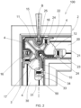
- window or door frame according to the invention is described, which is generally indicated by reference numeral 100.
- said frame (100) comprises a first profile (2), a second profile (3), and a corner joint (1) connecting said first profile (2) and said second profile (3).
- Said first profile (2) and said second profile (3) are made of a plastic material, preferably PVC.
- Each profile (2, 3) comprises a first side wall (21, 31) suitable for facing outwardly, and a second side wall (21a, 31a), opposite to said first side wall (21, 31) and suitable for facing inwardly.
- each profile (2, 3) comprises an outer wall (22, 32), facing the outside of the frame (100), and an inner wall (23, 33) opposite to the outer wall (22, 32).
- the first side wall (21, 31), the second side wall (21a, 31a), the outer wall (22, 32) and the inner wall (23, 33) of each profile (2, 3) define a longitudinal channel (20, 30) that can be axially accessed by means of an opening formed at one end of the profile (2, 3).
- An injection hole (25) is formed on the outer wall (22) of the first profile (2) for the injection of adhesive through an injection nozzle (B) in order to join the two profiles (2, 3).
- the corner joint (1) is housed in the longitudinal channels (20, 30) of said two profiles (2, 3) and comprises an inner surface (10) disposed in contact with the inner walls (23, 33) of the profiles (2, 3), and an outer surface (11) disposed in contact with the outer walls (22, 32) of the profiles (2, 3).
- the corner joint (1) additionally comprises a front face (12) disposed in contact with the second side walls (21a, 31a) of the two profiles (2, 3), and a rear face (13), opposite to the front face (12) and disposed in contact with the first side walls (21, 31) of the two profiles (2, 3).
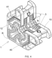
- Each one of the front and rear faces (12, 13) of the corner joint (1) comprises one or more lowered surfaces (4) defining seats (40) suitable for accommodating the adhesive that is injected through the injection hole (25) formed on the first profile (2).
- said lowered surfaces (4) can also be provided at only one of said two front and rear faces (12, 13) of the corner joint (1).
- the corner joint (1) also comprises retaining borders (SC) rising from the lowered surfaces (4) and defining the seat (40) at least partially, so as to contain the adhesive in the seat (40).
- the retaining border (SC) has a free end (SC1) suitable for abutting against an interior surface of the first side wall or of the second side wall of the profile.
- Each retaining border (SC) has a length equal to at least half the length of the perimeter of the respective lowered surface (4).
- the retaining borders (SC) are configured in such a way to contain the adhesive toward the center of the corner joint.
- a lowered space (R) (shown in Fig. 3 ) is formed in the retaining borders (SC) to let the adhesive flow toward the outer surface (11).
- the corner joint (1) comprises at least one inlet hole (15) formed on the outer surface (11) of the corner joint (1) in communication with the injection hole (25) of the first profile (2) to convey the adhesive toward the inside of the corner joint.
- said inlet hole (15) formed on the outer surface (11) of the corner joint (1) has an annular rib (15a) suitable for cooperating with the injection nozzle (B) in order to prevent the adhesive from spilling during the injection of the adhesive.
- the annular rib (15a) is in contact with the first profile (2), thus forming a gap between the first profile (2) and the outer surface (11) of the corner joint (1) which is suitable for accommodating the adhesive coming from the lowered surface (4) of the front and/or of the rear face (12, 13) and passing through said lowered space (R) of the retaining border (SC).
- the outer surface (11) comprises ribs (U) suitable for being drowned in the adhesive.
- the corner joint (1) further comprises, at least one outlet hole (16) formed on the front face and/or on the rear face (12, 13) of the corner joint (1) in communication with the inlet hole (15) to let the adhesive flow from said inlet hole (15) toward the seats (40) of the corner joint.
- each one of said front and rear faces (12, 13) of the corner joint (1) advantageously comprises four lowered surfaces (4) and two outlet holes (16) formed near the outer surface (11) of the corner joint.
- the corner joint (1) comprises a plurality of pegs (41) protruding outwardly from each one of said lowered surfaces (4) and suitable for being drowned in the adhesive conveyed into the seats (40) of the corner joint (1).
- the pegs (41) have a lower height (H41) than the height (HSC) of the retaining border (SC) and therefore they are not in contact with the inner surface of the side walls of the profiles.
- said pegs (41) are distributed at regular intervals alongside the retaining border (SC) along a trajectory that exactly reproduces the trajectory of the retaining border (SC). Because of such a peculiarity, the adhesive can flow freely on the central portion of the lowered surfaces (4) and can be uniformly distributed in the seats (40), thus drowning the pegs (41) and adhering to the first side wall (21, 31) and to the second side wall (21a, 31a) of the profiles (2, 3).
- a channeling hole (17) is formed on said front face (12) and/or on said rear face (13) of the corner joint (1), ending into the inner surface (10) of the corner joint (1), in such a way that the adhesive flows from the lowered surfaces (4) toward the inner surface (10) of the corner joint (1). More precisely, the channeling hole (17) ends into a lowered portion (N) of the inner surface (10) of the corner joint whereon ribs (T) are provided. Said ribs (T) of the inner surface (10) are suitable for being drowned in the adhesive.
- such a channeling hole (17) is formed on each one of the front and rear faces (12, 13) of the corner joint near the inner surface (10) of the corner joint.
- An outer channel (EC) connecting the two holes (16, 17) is provided between the channeling hole (17) and each outlet hole (16). Passages (P) are cut on the outer channel (EC) to let the adhesive flow out of the outer channel (EC) in order to be conveyed over the lowered surface (4) wherein the pegs (41) are provided.
- the adhesive injected from the injection hole (25) flows into the inlet hole (15) of the corner joint (1), ending into said outer channel (EC) through said outlet hole (16).
- the adhesive is propagated and distributed over the lowered surfaces (4) of the front and/or of the rear face (12, 13) and is finally conveyed toward the outer surface (11) of the corner joint (1) by passing through the lowered space (R) of the retaining border (SC).
- corner joint (1) is completely covered and drowned in the adhesive.
- the ribs (T, U) formed on the inner surface (10) and on the outer surface (11), as well as the pegs (41) formed on the lowered surface (4) of the front and rear faces (12, 13) of the corner joint (1) are suitable for distributing the adhesive uniformly, thus ensuring the optimal stability of the joint.
- the corner joint (1) of monolithic type comprises a first wing (1a) arranged in the longitudinal channel (20) of the first profile (2), and a second wing (1b) arranged in the longitudinal channel (30) of the second profile (3).
- the two wings (1a, 1b) are joined together to form an edge (1c) at the outer surface (11) of the corner joint.
- the two wings (1a, 1b) are specular with respect to a plane passing through the edge (1c) and through the axis of the channeling hole (17) of the corner joint.
- the front face (12) and the rear face (13) of each of said two wings (1a, 1b) is provided with an outlet hole (16) and two lowered surfaces (4).
- the first profile (2) is provided with an outlet hole (26) ( Fig. 1 ) formed on the relevant outer wall (22) and ending into the longitudinal channel (20) of the first profile.
- said outlet hole (26) is obtained in the vicinity of said injection hole (25) in order to be crossed by the adhesive when the profiles (2, 3) are completely adhered.
- the adhesive is suitable for flowing out of the outlet hole (26) of the first profile (2) when the sealing of the two profiles (2, 3) has been completed.
- each profile (2, 3) comprises at least one transverse opening (24, 34) in communication with the corresponding longitudinal channel (20, 30), and the corner joint (1) comprises threaded holes (5) formed on the inner surface (10) and/or on the outer surface (11) of the corner joint and aligned with said transverse openings (24, 34) of the profiles.
- fixing screws (50) can be threaded into said transverse openings (24, 34) of the profiles (2, 3) and screwed into said threaded holes (5) of the corner joint, so as to firmly join the two profiles (2, 3).
- said transverse openings (24, 34) are formed on both the outer wall (22, 32) and the inner wall (23, 33) of each profile, so that the profiles (2, 3) can be tightened either from the inside or from the outside, depending on the aesthetic requirements of the window frame.
- said threaded holes (5) are advantageously formed on both the inner (10) and outer (11) surfaces of the corner joint.
- the corner joint (1) further comprises end ribs (18) formed at end portions (11a) of the outer surface (11) of the corner joint (1) to eliminate any clearance between said corner joint (1) and the profiles (2, 3), so that the adhesive is contained between the outer surface (11) of the corner joint (1) and the outer walls (22, 32) of the profiles (2, 3), without flowing beyond the end portions (11a) of the outer surface (11) of the corner joint (1).
- the corner joint (1) can be provided with brackets (6a, 6b) protruding from the front and/or rear faces (12, 13) of the corner joint for the attachment of accessories.
- brackets (6a, 6b) protruding from the front and/or rear faces (12, 13) of the corner joint for the attachment of accessories.
- accessories such as, for example, a hinge or a stiffening profile, generally disposed in the longitudinal channels of the PVC profiles to impart greater strength to the window or door frame.
- the corner joint (1) advantageously comprises two front brackets (6a) that protrude from the front face (13) of the corner joint in an L-shaped conformation and are inserted into the longitudinal channels (20, 30) of the profiles, and two rear brackets (6b) that protrude from the rear face (12) of the bracket, in an L-shaped configuration, and are inserted into longitudinal channels (20, 30) of the profiles.
- Such an elastic behavior of the adhesive is also limited by the presence of the ribs (T, U) formed on the inner surface (10) and on the outer surface (11) of the corner joint (1).
Landscapes
- Engineering & Computer Science (AREA)
- Civil Engineering (AREA)
- Structural Engineering (AREA)
- Joining Of Corner Units Of Frames Or Wings (AREA)
Applications Claiming Priority (1)
| Application Number | Priority Date | Filing Date | Title |
|---|---|---|---|
| IT202300018834 | 2023-09-13 |
Publications (1)
| Publication Number | Publication Date |
|---|---|
| EP4524357A1 true EP4524357A1 (de) | 2025-03-19 |
Family
ID=88839057
Family Applications (1)
| Application Number | Title | Priority Date | Filing Date |
|---|---|---|---|
| EP24199956.4A Pending EP4524357A1 (de) | 2023-09-13 | 2024-09-12 | Eckverbindung für pvc-profile ohne schweissen |
Country Status (1)
| Country | Link |
|---|---|
| EP (1) | EP4524357A1 (de) |
Citations (4)
| Publication number | Priority date | Publication date | Assignee | Title |
|---|---|---|---|---|
| DE2307595A1 (de) | 1973-02-16 | 1974-08-29 | Guenter Dr-Ing Koepke | Distanzelemente fuer fenster, tueren und/ oder aehnliche bauelemente aus kunststoffhohlprofilen, insbesondere fuer deren verstaerkungswinkel und/oder -profile |
| EP0610675A1 (de) | 1993-02-10 | 1994-08-17 | SCHÜCO International KG | Eckverbindung auf Gehrung geschnittener Hohlprofile eines Rahmens für Fenster, Türen oder Fassaden (I) |
| DE102014116642A1 (de) * | 2014-11-13 | 2016-05-19 | Veka Ag | Verfahren zur In-Situ-Fertigung eines Eckverbinderelements in auf Gehrung geschnittenen Fenster- und Türprofilen und Eckverbinder-Fromelement dafür |
| WO2017035608A1 (en) * | 2015-08-28 | 2017-03-09 | Reynaers Aluminium, Naamloze Vennootschap | Corner piece for connecting metal window or door profiles at an angle to one another and the use thereof |
-
2024
- 2024-09-12 EP EP24199956.4A patent/EP4524357A1/de active Pending
Patent Citations (4)
| Publication number | Priority date | Publication date | Assignee | Title |
|---|---|---|---|---|
| DE2307595A1 (de) | 1973-02-16 | 1974-08-29 | Guenter Dr-Ing Koepke | Distanzelemente fuer fenster, tueren und/ oder aehnliche bauelemente aus kunststoffhohlprofilen, insbesondere fuer deren verstaerkungswinkel und/oder -profile |
| EP0610675A1 (de) | 1993-02-10 | 1994-08-17 | SCHÜCO International KG | Eckverbindung auf Gehrung geschnittener Hohlprofile eines Rahmens für Fenster, Türen oder Fassaden (I) |
| DE102014116642A1 (de) * | 2014-11-13 | 2016-05-19 | Veka Ag | Verfahren zur In-Situ-Fertigung eines Eckverbinderelements in auf Gehrung geschnittenen Fenster- und Türprofilen und Eckverbinder-Fromelement dafür |
| WO2017035608A1 (en) * | 2015-08-28 | 2017-03-09 | Reynaers Aluminium, Naamloze Vennootschap | Corner piece for connecting metal window or door profiles at an angle to one another and the use thereof |
Similar Documents
| Publication | Publication Date | Title |
|---|---|---|
| CN100404782C (zh) | 连接型材的锁角器和框架组件 | |
| US9718235B2 (en) | Corner joint and method of manufacturing | |
| US10890027B2 (en) | Corner key composite member | |
| US5894706A (en) | Molded window door and method | |
| US6463706B1 (en) | Unitary insulated glass unit and method of manufacture | |
| US9982477B1 (en) | Expandable, one-piece sill pan flashing | |
| CN101481981B (zh) | 墙壁、门或窗户组件 | |
| US11519216B2 (en) | Chassis based fenestration systems | |
| CA2497233A1 (en) | Window assembly having an outer sash frame supporting a removable inner sub-sash frame bonded to insulated glass panels | |
| US6746175B1 (en) | Fenestration corner lock | |
| GB2118668A (en) | Window frames | |
| EP4524357A1 (de) | Eckverbindung für pvc-profile ohne schweissen | |
| US11634943B2 (en) | Mullion joinery for window frame assembly | |
| EP3467249A1 (de) | Eckverbindung eines konstruktionsrahmens und verfahren zum herstellung dieser eckverbindung | |
| US7669380B2 (en) | Glue manifold for a functional shutter | |
| US20040078890A1 (en) | Plastic profile | |
| KR200196472Y1 (ko) | 건축용 패널의 조립구조 | |
| GB2248648A (en) | Sliding door and window frame joints and packing elements for such joints | |
| KR200499191Y1 (ko) | 창틀 코너 마감재 | |
| GB2109849A (en) | Bow windows | |
| KR102733263B1 (ko) | 창호용 커버 조립체 및 이를 포함하는 창호 | |
| US20240191557A1 (en) | Hybrid window frame assembly with improved corner seals | |
| FI65842C (fi) | Foerfarande foer framstaellning av foensterkarmar och -baogar samt saolunda framstaelld karm- och baogkonstruktion. | |
| CA1160511A (en) | Window frames | |
| WO1995034737A1 (en) | System of profiles for a window or a door and a joint in casings or frames |
Legal Events
| Date | Code | Title | Description |
|---|---|---|---|
| PUAI | Public reference made under article 153(3) epc to a published international application that has entered the european phase |
Free format text: ORIGINAL CODE: 0009012 |
|
| STAA | Information on the status of an ep patent application or granted ep patent |
Free format text: STATUS: THE APPLICATION HAS BEEN PUBLISHED |
|
| AK | Designated contracting states |
Kind code of ref document: A1 Designated state(s): AL AT BE BG CH CY CZ DE DK EE ES FI FR GB GR HR HU IE IS IT LI LT LU LV MC ME MK MT NL NO PL PT RO RS SE SI SK SM TR |
|
| STAA | Information on the status of an ep patent application or granted ep patent |
Free format text: STATUS: REQUEST FOR EXAMINATION WAS MADE |
|
| 17P | Request for examination filed |
Effective date: 20250916 |