EP4524367A1 - Rotorsystem für einen turbinenmotor - Google Patents
Rotorsystem für einen turbinenmotor Download PDFInfo
- Publication number
- EP4524367A1 EP4524367A1 EP24190396.2A EP24190396A EP4524367A1 EP 4524367 A1 EP4524367 A1 EP 4524367A1 EP 24190396 A EP24190396 A EP 24190396A EP 4524367 A1 EP4524367 A1 EP 4524367A1
- Authority
- EP
- European Patent Office
- Prior art keywords
- stator vanes
- uniform
- nug
- stator
- rotor
- Prior art date
- Legal status (The legal status is an assumption and is not a legal conclusion. Google has not performed a legal analysis and makes no representation as to the accuracy of the status listed.)
- Pending
Links
Images


Classifications
-
- F—MECHANICAL ENGINEERING; LIGHTING; HEATING; WEAPONS; BLASTING
- F01—MACHINES OR ENGINES IN GENERAL; ENGINE PLANTS IN GENERAL; STEAM ENGINES
- F01D—NON-POSITIVE DISPLACEMENT MACHINES OR ENGINES, e.g. STEAM TURBINES
- F01D25/00—Component parts, details, or accessories, not provided for in, or of interest apart from, other groups
- F01D25/04—Antivibration arrangements
-
- F—MECHANICAL ENGINEERING; LIGHTING; HEATING; WEAPONS; BLASTING
- F01—MACHINES OR ENGINES IN GENERAL; ENGINE PLANTS IN GENERAL; STEAM ENGINES
- F01D—NON-POSITIVE DISPLACEMENT MACHINES OR ENGINES, e.g. STEAM TURBINES
- F01D5/00—Blades; Blade-carrying members; Heating, heat-insulating, cooling or antivibration means on the blades or the members
- F01D5/12—Blades
- F01D5/26—Antivibration means not restricted to blade form or construction or to blade-to-blade connections or to the use of particular materials
-
- F—MECHANICAL ENGINEERING; LIGHTING; HEATING; WEAPONS; BLASTING
- F01—MACHINES OR ENGINES IN GENERAL; ENGINE PLANTS IN GENERAL; STEAM ENGINES
- F01D—NON-POSITIVE DISPLACEMENT MACHINES OR ENGINES, e.g. STEAM TURBINES
- F01D5/00—Blades; Blade-carrying members; Heating, heat-insulating, cooling or antivibration means on the blades or the members
- F01D5/02—Blade-carrying members, e.g. rotors
-
- F—MECHANICAL ENGINEERING; LIGHTING; HEATING; WEAPONS; BLASTING
- F01—MACHINES OR ENGINES IN GENERAL; ENGINE PLANTS IN GENERAL; STEAM ENGINES
- F01D—NON-POSITIVE DISPLACEMENT MACHINES OR ENGINES, e.g. STEAM TURBINES
- F01D25/00—Component parts, details, or accessories, not provided for in, or of interest apart from, other groups
- F01D25/04—Antivibration arrangements
- F01D25/06—Antivibration arrangements for preventing blade vibration
-
- F—MECHANICAL ENGINEERING; LIGHTING; HEATING; WEAPONS; BLASTING
- F01—MACHINES OR ENGINES IN GENERAL; ENGINE PLANTS IN GENERAL; STEAM ENGINES
- F01D—NON-POSITIVE DISPLACEMENT MACHINES OR ENGINES, e.g. STEAM TURBINES
- F01D5/00—Blades; Blade-carrying members; Heating, heat-insulating, cooling or antivibration means on the blades or the members
- F01D5/02—Blade-carrying members, e.g. rotors
- F01D5/10—Anti- vibration means
-
- F—MECHANICAL ENGINEERING; LIGHTING; HEATING; WEAPONS; BLASTING
- F01—MACHINES OR ENGINES IN GENERAL; ENGINE PLANTS IN GENERAL; STEAM ENGINES
- F01D—NON-POSITIVE DISPLACEMENT MACHINES OR ENGINES, e.g. STEAM TURBINES
- F01D5/00—Blades; Blade-carrying members; Heating, heat-insulating, cooling or antivibration means on the blades or the members
- F01D5/12—Blades
- F01D5/14—Form or construction
- F01D5/16—Form or construction for counteracting blade vibration
-
- F—MECHANICAL ENGINEERING; LIGHTING; HEATING; WEAPONS; BLASTING
- F01—MACHINES OR ENGINES IN GENERAL; ENGINE PLANTS IN GENERAL; STEAM ENGINES
- F01D—NON-POSITIVE DISPLACEMENT MACHINES OR ENGINES, e.g. STEAM TURBINES
- F01D9/00—Stators
- F01D9/02—Nozzles; Nozzle boxes; Stator blades; Guide conduits, e.g. individual nozzles
- F01D9/04—Nozzles; Nozzle boxes; Stator blades; Guide conduits, e.g. individual nozzles forming ring or sector
- F01D9/041—Nozzles; Nozzle boxes; Stator blades; Guide conduits, e.g. individual nozzles forming ring or sector using blades
-
- F—MECHANICAL ENGINEERING; LIGHTING; HEATING; WEAPONS; BLASTING
- F04—POSITIVE - DISPLACEMENT MACHINES FOR LIQUIDS; PUMPS FOR LIQUIDS OR ELASTIC FLUIDS
- F04D—NON-POSITIVE-DISPLACEMENT PUMPS
- F04D29/00—Details, component parts, or accessories
- F04D29/40—Casings; Connections of working fluid
- F04D29/52—Casings; Connections of working fluid for axial pumps
- F04D29/54—Fluid-guiding means, e.g. diffusers
- F04D29/541—Specially adapted for elastic fluid pumps
- F04D29/542—Bladed diffusers
-
- F—MECHANICAL ENGINEERING; LIGHTING; HEATING; WEAPONS; BLASTING
- F04—POSITIVE - DISPLACEMENT MACHINES FOR LIQUIDS; PUMPS FOR LIQUIDS OR ELASTIC FLUIDS
- F04D—NON-POSITIVE-DISPLACEMENT PUMPS
- F04D29/00—Details, component parts, or accessories
- F04D29/66—Combating cavitation, whirls, noise, vibration or the like; Balancing
- F04D29/661—Combating cavitation, whirls, noise, vibration or the like; Balancing especially adapted for elastic fluid pumps
- F04D29/666—Combating cavitation, whirls, noise, vibration or the like; Balancing especially adapted for elastic fluid pumps by means of rotor construction or layout, e.g. unequal distribution of blades or vanes
-
- F—MECHANICAL ENGINEERING; LIGHTING; HEATING; WEAPONS; BLASTING
- F04—POSITIVE - DISPLACEMENT MACHINES FOR LIQUIDS; PUMPS FOR LIQUIDS OR ELASTIC FLUIDS
- F04D—NON-POSITIVE-DISPLACEMENT PUMPS
- F04D29/00—Details, component parts, or accessories
- F04D29/66—Combating cavitation, whirls, noise, vibration or the like; Balancing
- F04D29/661—Combating cavitation, whirls, noise, vibration or the like; Balancing especially adapted for elastic fluid pumps
- F04D29/668—Combating cavitation, whirls, noise, vibration or the like; Balancing especially adapted for elastic fluid pumps damping or preventing mechanical vibrations
-
- F—MECHANICAL ENGINEERING; LIGHTING; HEATING; WEAPONS; BLASTING
- F05—INDEXING SCHEMES RELATING TO ENGINES OR PUMPS IN VARIOUS SUBCLASSES OF CLASSES F01-F04
- F05D—INDEXING SCHEME FOR ASPECTS RELATING TO NON-POSITIVE-DISPLACEMENT MACHINES OR ENGINES, GAS-TURBINES OR JET-PROPULSION PLANTS
- F05D2220/00—Application
- F05D2220/30—Application in turbines
- F05D2220/32—Application in turbines in gas turbines
- F05D2220/323—Application in turbines in gas turbines for aircraft propulsion, e.g. jet engines
-
- F—MECHANICAL ENGINEERING; LIGHTING; HEATING; WEAPONS; BLASTING
- F05—INDEXING SCHEMES RELATING TO ENGINES OR PUMPS IN VARIOUS SUBCLASSES OF CLASSES F01-F04
- F05D—INDEXING SCHEME FOR ASPECTS RELATING TO NON-POSITIVE-DISPLACEMENT MACHINES OR ENGINES, GAS-TURBINES OR JET-PROPULSION PLANTS
- F05D2240/00—Components
- F05D2240/10—Stators
- F05D2240/12—Fluid guiding means, e.g. vanes
-
- F—MECHANICAL ENGINEERING; LIGHTING; HEATING; WEAPONS; BLASTING
- F05—INDEXING SCHEMES RELATING TO ENGINES OR PUMPS IN VARIOUS SUBCLASSES OF CLASSES F01-F04
- F05D—INDEXING SCHEME FOR ASPECTS RELATING TO NON-POSITIVE-DISPLACEMENT MACHINES OR ENGINES, GAS-TURBINES OR JET-PROPULSION PLANTS
- F05D2240/00—Components
- F05D2240/20—Rotors
- F05D2240/24—Rotors for turbines
-
- F—MECHANICAL ENGINEERING; LIGHTING; HEATING; WEAPONS; BLASTING
- F05—INDEXING SCHEMES RELATING TO ENGINES OR PUMPS IN VARIOUS SUBCLASSES OF CLASSES F01-F04
- F05D—INDEXING SCHEME FOR ASPECTS RELATING TO NON-POSITIVE-DISPLACEMENT MACHINES OR ENGINES, GAS-TURBINES OR JET-PROPULSION PLANTS
- F05D2260/00—Function
- F05D2260/96—Preventing, counteracting or reducing vibration or noise
- F05D2260/961—Preventing, counteracting or reducing vibration or noise by mistuning rotor blades or stator vanes with irregular interblade spacing, airfoil shape
Definitions
- the present disclosure relates generally to rotor systems for turbine engines.
- a turbine engine for example, for an aircraft, generally includes a fan and a core section arranged in flow communication with one another.
- Such turbine engines typically include a rotor system including a rotor assembly having a plurality of rotor blades and a stator assembly having a plurality of stator vanes.
- first,” “second,” “third,” “fourth,” and “fifth” may be used interchangeably to distinguish one component from another and are not intended to signify location or importance of the individual components.
- upstream and downstream refer to the relative direction with respect to fluid flow in a fluid pathway.
- upstream refers to the direction from which the fluid flows
- downstream refers to the direction to which the fluid flows.
- forward and aft refer to relative positions within a turbine engine or a vehicle and refer to the normal operational attitude of the turbine engine or vehicle.
- forward refers to a position closer to an engine inlet and aft refers to a position closer to an engine nozzle or exhaust.
- Coupled refers to both direct coupling, fixing, attaching, or connecting, as well as indirect coupling, fixing, attaching, or connecting through one or more intermediate components or features, unless otherwise specified herein.
- the terms “axial” and “axially” refer to directions and orientations that extend substantially parallel to a centerline of the turbine engine.
- the terms “radial” and “radially” refer to directions and orientations that extend substantially perpendicular to the centerline of the turbine engine.
- the terms “circumferential” and “circumferentially” refer to directions and orientations that extend arcuately about the centerline of the turbine engine.
- spacing of stator vanes is a circumferential spacing between adjacent stator vanes of a stator assembly.
- uniform spacing of the stator vanes is a uniform spacing between at least two stator vanes being the same as the spacing between at least two other stator vanes.
- a non-uniform gap is defined by the spacing between at least two stator vanes being different than the spacing between at least two other stator vanes.
- a non-uniform gap is different than the uniform spacing.
- a "one nodal diameter system response" is a vibrational response in which the stator vanes on one half of the stator assembly (e.g., the stator vanes positioned at a circumferential position between 0° to 180° on the stator assembly) are vibrating 180° out of phase with the stator vanes on the other half of the stator assembly (e.g., the stator vanes positioned at a circumferential position between 180° to 360° on the stator assembly).
- Such a vibrational response generates an unbalanced moment that is transmitted from the stator assembly.
- a vibrational response is "balanced" about an axis N (e.g., an X-axis or a Y-axis) when the vibrational response exists for a pair of stator vanes on both sides of the axis N such that the absolute value of the amplitude of the vibrational response for each of the pair of stator vanes is substantially equal.
- axis N e.g., an X-axis or a Y-axis
- Turbine engines for example, for aircraft, include rotor systems that include a rotor assembly having rotor blades and a stator assembly having stator vanes.
- the rotor systems can include a fan of the turbine engine and a plurality of outlet guide vanes, one or more stages of compressor rotor blades and compressor stator vanes, or one or more stages of turbine rotor blades and turbine stator vanes.
- the unequilibrated system mode response in a uniformly spaced stator assembly is managed by ensuring that the number of stator vanes of the stator assembly is different than the number of rotor blades of the rotor assembly by at least two or more (and any integer multiple of the number of rotor blades). For example, if there are thirty rotor blades on the rotor assembly, the stator assembly includes fewer than or equal to twenty-eight stator vanes or greater than or equal to thirty-two stator vanes.
- the first non-uniform gap is different than the second non-uniform gap to eliminate, or to prevent, the zero nodal diameter system response. In another embodiment, the first non-uniform gap is equal to the second non-uniform gap to eliminate, or to prevent, the one nodal diameter system response.
- the rotor assembly includes any even number of rotor blades, and the stator assembly includes any even number of stator vanes.
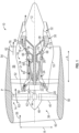
- the core turbine engine 16 depicted generally includes an outer casing 18 that is substantially tubular and defines an annular inlet 20. As schematically shown in FIG. 1 , the outer casing 18 encases, in serial flow relationship, a compressor section 21 including a booster or a low pressure (LP) compressor 22 followed downstream by a high pressure (HP) compressor 24, a combustion section 26, a turbine section 27 including a high pressure (HP) turbine 28 followed downstream by a low pressure (LP) turbine 30, and a jet exhaust nozzle section 32.
- a high pressure (HP) shaft 34 or spool drivingly connects the HP turbine 28 to the HP compressor 24 to rotate the HP turbine 28 and the HP compressor 24 in unison.
- the fan section 14 includes a fan 38 (e.g., a variable pitch fan) having a plurality of fan blades 40 coupled to a disk 42 in a spaced apart manner.
- the fan blades 40 extend outwardly from the disk 42 generally along the radial direction R.
- Each fan blade 40 is rotatable relative to the disk 42 about a pitch axis P by virtue of the fan blades 40 being operatively coupled to an actuation member 44 configured to collectively vary the pitch of the fan blades 40 in unison, as detailed further below.
- the fan blades 40, the disk 42, and the actuation member 44 are together rotatable about the longitudinal centerline axis 12 via a fan shaft 45 that is powered by the LP shaft 36 across a power gearbox, also referred to as a gearbox assembly 46.
- the gearbox assembly 46 is shown schematically in FIG. 1 .
- the gearbox assembly 46 includes a plurality of gears for adjusting the rotational speed of the fan shaft 45 and, thus, the fan 38 relative to the LP shaft 36.
- the disk 42 is covered by a rotatable fan hub 48 aerodynamically contoured to promote an airflow through the plurality of fan blades 40.
- the fan section 14 includes an annular fan casing or a nacelle 50 that circumferentially surrounds the fan 38 and/or at least a portion of the core turbine engine 16.
- the nacelle 50 is supported relative to the core turbine engine 16 by a plurality of outlet guide vanes 52 that are spaced circumferentially about the nacelle 50.
- a downstream section 54 of the nacelle 50 extends over an outer portion of the core turbine engine 16 to define a bypass airflow passage 56 therebetween.
- a volume of air 58 enters the turbine engine 10 through an inlet 60 of the nacelle 50 and/or the fan section 14.
- a first portion of air 62 is directed or routed into the bypass airflow passage 56
- a second portion of air 64 is directed or is routed into the upstream section of the core air flow path, or, more specifically, into the annular inlet 20 of the LP compressor 22.
- the ratio between the first portion of air 62 and the second portion of air 64 is commonly known as a bypass ratio.
- the pressure of the second portion of air 64 is then increased, forming compressed air 65, and the compressed air 65 is routed through the HP compressor 24 and into the combustion section 26, where the compressed air 65 is mixed with fuel and burned to generate combustion gases 66.
- the combustion gases 66 are routed into the HP turbine 28 and expanded through the HP turbine 28 where a portion of thermal energy and/or kinetic energy from the combustion gases 66 is extracted via sequential stages of HP turbine stator vanes 68 that are coupled to the outer casing 18 and HP turbine rotor blades 70 that are coupled to the HP shaft 34, thus, causing the HP shaft 34 to rotate, which supports operation of the HP compressor 24.
- the combustion gases 66 are then routed into the LP turbine 30 and expanded through the LP turbine 30.
- the turbine engine 10 depicted in FIG. 1 is by way of example only.
- the turbine engine 10 may have any other suitable configuration.
- the fan 38 may be configured in any other suitable manner (e.g., as a fixed pitch fan) and further may be supported using any other suitable fan frame configuration.
- any other suitable number or configuration of compressors, turbines, shafts, or a combination thereof may be provided.
- aspects of the present disclosure may be incorporated into any other suitable turbine engine, such as, for example, turbofan engines, propfan engines, turbojet engines, turboprop, and/or turboshaft engines.
- FIG. 2 is a schematic plan view of a portion of a rotor system 200 for the turbine engine 10 of FIG. 1 , according to the present disclosure.
- the rotor system 200 can be utilized as any of the rotor systems of the turbine engine 10 that have one or more stages of rotating blades and static vanes.
- the rotor system 200 can be utilized as the fan section 14 (e.g., the fan 38 and the plurality of outlet guide vanes 52), at least a portion of the compressor section 21, or at least a portion of the turbine section 27.
- the rotor system 200 includes a rotor assembly 202 having a plurality of rotor blades 204 and a stator assembly 206 having a plurality of stator vanes 208.
- the plurality of rotor blades 204 is supported by rotor disks on the rotor assembly 202, and the rotor assembly 202 is coupled to a rotating shaft (e.g., the fan shaft 45, the HP shaft 34, or the LP shaft 36 of FIG. 1 ).
- the stator assembly 206 is a static component such that the stator assembly 206, and, thus, the plurality of stator vanes 208, does not rotate circumferentially.
- the plurality of stator vanes 208 includes variable stator vanes such that the plurality of stator vanes 208 can be pitched about a pitch axis to change a pitch of the plurality of stator vanes 208.
- the stator assembly 206 is positioned downstream of the rotor assembly 202. As shown in FIG. 2 , air 211 flows axially between the plurality of rotor blades 204 and the plurality of stator vanes 208.
- the rotor assembly 202 rotates (as indicated by arrow 213) to rotate the plurality of rotor blades 204 circumferentially about the longitudinal centerline axis 12 ( FIG. 1 ).
- Rotation of the plurality of rotor blades 204 causes the air 211 to flow between the plurality of rotor blades 204.
- the plurality of stator vanes 208 directs the air 211 through the plurality of stator vanes 208.
- the plurality of rotor blades 204 is spaced uniformly about the rotor assembly 202. For example, the circumferential spacing between the plurality of rotor blades 204 is substantially equal.
- the plurality of stator vanes 208 includes both uniform spacing and non-uniform gaps, as detailed further below.
- FIG. 3 is a schematic diagram of a front view of the stator assembly 206, according to the present disclosure.
- the plurality of stator vanes 208 includes sixteen stator vanes 208 that are spaced circumferentially about the stator assembly 206.
- the stator assembly 206 may be viewed with respect to a "clock" orientation having a twelve o'clock position 220, a three o'clock position 222, a six o'clock position 224, and a nine o'clock position 226.
- the clock orientation is understood to include all clock positions therebetween.
- the stator assembly 206 is divided into three groups including a first group of stator vanes 230, a second group of stator vanes 240, and a third group of stator vanes 250.
- the first group of stator vanes 230 includes two stator vanes 208
- the second group of stator vanes 240 includes two stator vanes 208
- the third group of stator vanes 250 includes a remainder of the number of stator vanes 208.
- adjacent stator vanes 208 have a first non-uniform gap (NUG 1 ).
- Adjacent stator vanes 208 are defined as two stator vanes 208 that are directly circumferentially next to each other with no intervening stator vanes 208.
- adjacent stator vanes 208 have a second non-uniform gap (NUG 2 ).
- NUG 2 non-uniform gap
- adjacent stator vanes 208 have a uniform spacing (US).
- US uniform spacing
- the stator assembly 206 includes a circumferential spacing of the plurality of stator vanes 208 that includes at least one pair of non-uniform gaps (NUGs), including the first non-uniform gap NUG 1 and the second non-uniform gap NUG 2 .
- NUGs non-uniform gaps
- a non-uniform gap is defined by the spacing between at least two stator vanes 208 being different than the spacing between at least two other stator vanes 208.
- the at least one pair of non-uniform gaps NUG 1 , NUG 2 are opposite each other.
- the first non-uniform gap NUG 1 is spaced one hundred and eighty degrees (180°) from the second non-uniform gap NUG 2 .
- the first non-uniform gap NUG 1 is positioned at the twelve o'clock position 220, and the second non-uniform gap NUG 2 is positioned at the six o'clock position 224.
- the first non-uniform gap NUG 1 and the second non-uniform gap NUG 2 can be positioned at any "clock" position on the stator assembly 206 as long as the first non-uniform gap NUG 1 is spaced one hundred and eighty degrees (180°) from the second non-uniform gap NUG 2 .
- the stator assembly 206 also includes stator vanes 208 that are spaced by the uniform spacing US between stator vanes 208 that are not spaced by the at least one pair of non-uniform gaps NUG 1 , NUG 2 .
- stator vanes 208 that are spaced by the uniform spacing US between stator vanes 208 that are not spaced by the at least one pair of non-uniform gaps NUG 1 , NUG 2 are spaced by the uniform spacing US.
- the at least one pair of non-uniform gaps NUG 1 , NUG 2 and the uniform spacing US may be defined by an angular measurement.
- the angular measurement is defined by a spacing measured with respect to an angle created between adjacent stator vanes 208.
- an angle 280 may be defined between an axis 282 of a first stator vane 290 extending through and perpendicular to the longitudinal centerline axis 12 and an axis 284 of a second, adjacent stator vane 292 extending through and perpendicular to the longitudinal centerline axis 12.
- the measured angle 280 defines the uniform spacing US.
- an angular measurement is also used to determine the first non-uniform gap NUG 1 and the second non-uniform gap NUG 2 .
- the angular measurements of the first non-uniform gap NUG 1 and the second non-uniform gap NUG 2 may be measured between axis of adjacent stator vanes as described with respect to the first spacing S1.
- the first non-uniform gap NUG 1 is different from (e.g., not equal to) the second non-uniform gap NUG 2 .
- the uniform spacing US is different from the first non-uniform gap NUG 1 and the second non-uniform gap NUG 2 .
- Such a configuration eliminates the zero nodal diameter system response by having the vibratory response be balanced, as detailed further below with respect to the example of FIGS. 4A to 4D .
- the first non-uniform gap NUG 1 is greater than the second non-uniform gap NUG 2 .
- N B is a number of rotor blades 204 on the rotor assembly 202
- Ns is a number of stator vanes 208 on the stator assembly 206
- US is the uniform spacing as detailed further below.
- N B and Ns are selected such that the plurality of rotor blades 204 includes an even number of rotor blades 204 and the plurality of stator vanes 208 includes an even number of stator vanes 208, respectively.
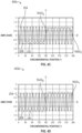
- FIGS. 4A to 4D illustrate exemplary graphs of a waveform of a stimulus (e.g., pressure changes) from the rotor blades 204 on each of the stator vanes 208 at various phases, according to the present disclosure.
- the waveform of the rotor blades 204 is a sinusoidal waveform.
- FIG. 4A illustrates a graph 400a of the waveform of the rotor blades 204 at an initial condition (0° phase).
- FIG. 4B illustrates a graph 400b of the waveform of the rotor blades 204 at a 30° phase shift.
- FIG. 4C illustrates a graph 400c of the waveform of the rotor blades 204 at a 60° phase shift.
- FIGS. 4A to 4D illustrates a graph 400d of the waveform of the rotor blades 204 at a 90° phase shift.
- the rotor blades 204 are represented by a sine wave as the rotor blades 204 rotate
- the stator vanes 208 are represented by squares at various circumferential positions of the stator assembly 206 ( FIG. 2 ).
- FIGS. 4A to 4D show the uniform spacing US, the first non-uniform gap NUG 1 , and the second non-uniform gap NUG 2 .
- FIGS. 4A to 4D illustrate a first example of the at least one pair of non-uniform gaps NUG 1 , NUG 2 , and the uniform spacing US.
- the rotor assembly 202 includes eighteen rotor blades 204 and the stator assembly 206 includes sixteen stator vanes 208.
- the uniform spacing US can be any uniform spacing and is selected based on a balance of acoustics, aerodynamics, mechanical design integration, or the like.
- the uniform spacing US is twenty degrees (20°) such that the stator vanes 208 would be spaced 20° from each other if there were eighteen stator vanes 208 (e.g., 360°/18 equals 20°).
- the first non-uniform gap NUG 1 is determined by relationship (1)
- the second non-uniform gap NUG 2 is determined by relationship (2), above.
- N B is eighteen
- Ns is sixteen
- the uniform spacing US is 20°
- the first non-uniform gap NUG 1 is fifty degrees (50°) per relationship (1)
- the second non-uniform gap NUG 2 is thirty degrees (30°) per relationship (2).
- the vibration response on the stator vanes 208 is balanced about the X-axis.
- the vibration response of the eight stator vanes 208 that are positioned between 0° to 180° on the stator assembly 206 moves from zero amplitude to negative one (-1) amplitude as the phase changes from the initial condition (graph 400a in FIG. 4A ) to the 90° phase shift (graph 400d in FIG. 4D ).
- the vibration response on the eight stator vanes 208 that are positioned between 180° to 360° on the stator assembly 206 moves from zero amplitude to positive one (1) amplitude as the phase changes from the initial condition (graph 400a in FIG. 4A ) to the 90° phase shift (graph 400d in FIG.
- stator assembly 206 having at least one pair of non-uniform gaps NUG 1 , NUG 2 that are different eliminates the zero nodal diameter system response, and the unbalanced force between the twelve o'clock position 220 and the six o'clock position 224 is eliminated as compared to stator assemblies without the benefit of the present disclosure.
- stator assembly 206 having at least one pair of non-uniform gaps NUG 1 , NUG 2 that are different prevents the zero nodal diameter system response (e.g., prevents the unbalanced force) through the turbine engine 10 ( FIG. 1 ).
- FIG. 5 is a schematic diagram of a front view of a stator assembly 506, according to another embodiment.
- the stator assembly 506 includes a plurality of stator vanes 508 and can be utilized as the stator assembly 206 in the rotor system 200 of FIG. 2 .
- the plurality of stator vanes 508 includes sixteen stator vanes 508 that are spaced circumferentially about the stator assembly 506.
- the stator assembly 506 may be viewed with respect to a "clock" orientation having a twelve o'clock position 520, a three o'clock position 522, a six o'clock position 524, and a nine o'clock position 526.
- the clock orientation is understood to include all clock positions therebetween.
- the stator assembly 506 is divided into three groups including a first group of stator vanes 530, a second group of stator vanes 540, and a third group of stator vanes 550.
- the first group of stator vanes 530 includes two stator vanes 508, the second group of stator vanes 540 includes two stator vanes 508, and the third group of stator vanes 550 includes a remainder of the number of stator vanes 508.
- adjacent stator vanes 508 have a first non-uniform gap (NUG 1 ).
- adjacent stator vanes 508 In the second group of stator vanes 540, adjacent stator vanes 508 have a second non-uniform gap (NUG 2 ).
- stator vanes 550 In the third group of stator vanes 550, adjacent stator vanes 508 have a uniform spacing (US). There are two third groups of stator vanes 550 that are positioned between the first group of stator vanes 530 and the second group of stator vanes 540.
- the stator assembly 506 includes a circumferential spacing of the plurality of stator vanes 508 that includes at least one pair of non-uniform gaps (NUGs), including the first non-uniform gap NUG 1 and the second non-uniform gap NUG 2 .
- the at least one pair of non-uniform gaps NUG 1 , NUG 2 are opposite each other.
- the first non-uniform gap NUG 1 is spaced one hundred and eighty degrees (180°) from the second non-uniform gap NUG 2 .
- the first non-uniform gap NUG 1 is positioned at the twelve o'clock position 520
- the second non-uniform gap NUG 2 is positioned at the six o'clock position 524.
- the first non-uniform gap NUG 1 and the second non-uniform gap NUG 2 can be positioned at any "clock" position on the stator assembly 506 as long as the first non-uniform gap NUG 1 is spaced one hundred and eighty degrees (180°) from the second non-uniform gap NUG 2 .
- the stator assembly 506 also includes stator vanes 508 that are spaced by the uniform spacing US between stator vanes 508 that are not spaced by the at least one pair of non-uniform gaps NUG 1 , NUG 2 .
- stator vanes 508 that are spaced by the uniform spacing US between stator vanes 508 that are not spaced by the at least one pair of non-uniform gaps NUG 1 , NUG 2 are spaced by the uniform spacing US.
- there are two stator vanes 508 that are spaced by the first non-uniform gap NUG 1 there are two stator vanes 508 that are spaced by the second non-uniform gap NUG 2 , and twelve stator vanes 508 that are spaced by the uniform spacing US.
- the at least one pair of non-uniform gaps NUG 1 , NUG 2 , and the uniform spacing US may be defined by an angular measurement, as detailed above with respect to FIG. 3 .
- the first non-uniform gap NUG 1 is equal to the second non-uniform gap NUG 2 .
- the uniform spacing US is different from the first non-uniform gap NUG 1 and the second non-uniform gap NUG 2 .
- Such a configuration eliminates the one nodal diameter system response by having the vibratory response be balanced, as detailed further below with respect to the example of FIGS. 6A to 6D .
- the first non-uniform gap NUG 1 and the second non-uniform gap NUG 2 are determined based on three hundred sixty degrees (360°), minus the number of gaps that are spaced by the uniform spacing US, multiplied by the uniform spacing US, and divided by the number of non-uniform gaps.
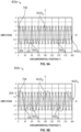
- FIGS. 6A to 6D illustrate exemplary graphs of a waveform of a stimulus from the rotor blades 204 on each of the stator vanes 508 at various phases, according to the present disclosure.
- the waveform of the rotor blades 204 is a sinusoidal waveform.
- FIG. 6A illustrates a graph 600a of the waveform of the rotor blades 204 at an initial condition (0° phase).
- FIG. 6B illustrates a graph 600b of the waveform of the rotor blades 204 at a 30° phase shift.
- FIG. 6C illustrates a graph 600c of the waveform of the rotor blades 204 at a 60° phase shift.
- FIGS. 6A to 6D illustrates a graph 600d of the waveform of the rotor blades 204 at a 90° phase shift.
- the stimulus of the rotor blades 204 is represented by a sine wave as the rotor blades 204 rotate
- the stator vanes 508 are represented by squares at various circumferential positions of the stator assembly 506 ( FIG. 5 ).
- FIGS. 6A to 6D show the uniform spacing US, the first non-uniform gap NUG 1 , and the second non-uniform gap NUG 2 .
- FIGS. 6A to 6D illustrate a second example of the at least one pair of non-uniform gaps NUG 1 , NUG 2 , and the uniform spacing US.
- the rotor assembly 202 includes eighteen rotor blades 204 and the stator assembly 506 includes sixteen stator vanes 508.
- the uniform spacing US is selected based on a uniform spacing if there was one fewer stator vane 208 than the number of rotor blades 204.
- the uniform spacing US is approximately twenty-one point two degrees (21.2°) such that the stator vanes 508 would be spaced approximately 21.2° from each other if there were seventeen stator vanes 508 (e.g., 360°/17 equals approximately 21.2°).
- the first non-uniform gap NUG 1 and the second non-uniform gap NUG 2 are determined by a remainder of the spacing after the uniform spacing US has been subtracted from 360°, and the first non-uniform gap NUG 1 equals the second non-uniform gap NUG 2 .
- N S is sixteen and there are two non-uniform gaps (e.g., NUG 1 , NUG 2 ), then there are fourteen gaps between stator vanes 508 that are spaced by the uniform spacing US.
- the vibration response on the stator vanes 508 is balanced about the Y-axis.
- the vibration response of the eight stator vanes 508 that are positioned between 0° to 180° on the stator assembly 506 is equal to the vibration response of the eight stator vanes 508 that are positioned between 180° to 360° on the stator assembly 506 as the phase changes from the initial condition (graph 600a in FIG. 6D ) to the 90° phase shift (graph 600d in FIG. 6D ).
- the vibration response of the eight stator vanes 508 that are positioned between 0° to 180° on the stator assembly 506 is repeated by the vibration response of the eight stator vanes 508 that are positioned between 180° to 360° about the Y-axis such that the vibration response of the stator vanes 508 is balanced about the Y-axis.
- the stator assembly 506 having at least one pair of non-uniform gaps NUG 1 , NUG 2 that are equal eliminates the one nodal diameter system response, and the unbalanced moment between the three o'clock position 522 and the nine o'clock position 526 is eliminated as compared to stator assemblies without the benefit of the present disclosure.
- the stator assembly 506 has at least one pair of non-uniform gaps NUG 1 , NUG 2 that are equal prevents the one nodal diameter system response (e.g., prevents the unbalanced moment) through the turbine engine 10 ( FIG. 1 ).
- FIG. 7 is a schematic diagram of a front view of a stator assembly 706, according to another embodiment.
- the stator assembly 706 includes a plurality of stator vanes 708 and can be utilized as the stator assembly 206 in the rotor system 200 of FIG. 2 .
- the plurality of stator vanes 708 includes sixteen stator vanes 708 that are spaced circumferentially about the stator assembly 706.
- the stator assembly 706 may be viewed with respect to a "clock" orientation having a twelve o'clock position 720, a three o'clock position 722, a six o'clock position 724, and a nine o'clock position 726.
- the clock orientation is understood to include all clock positions therebetween.
- the stator assembly 706 is divided into five groups including a first group of stator vanes 730, a second group of stator vanes 740, a third group of stator vanes 750, a fourth group of stator vanes 760, and a fifth group of stator vanes 770.
- the first group of stator vanes 730 includes two stator vanes 708,
- the second group of stator vanes 740 includes two stator vanes 708,
- the third group of stator vanes 750 includes a remainder of the number of stator vanes 708,
- the fourth group of stator vanes 760 includes two stator vanes 708, and the fifth group of stator vanes 770 includes two stator vanes 708.
- adjacent stator vanes 708 have a first non-uniform gap (NUG 1 ).
- adjacent stator vanes 708 have a second non-uniform gap (NUG 2 ).
- adjacent stator vanes 708 have a uniform spacing (US).
- adjacent stator vanes 708 have a third non-uniform gap (NUG 3 ).
- adjacent stator vanes 708 have a fourth non-uniform gap (NUG 4 ).
- stator vanes 708 in the third group of stators vanes 750 including two stator vanes 708 of the third group of stator vanes 750 positioned between the first group of stator vanes 730 and the fourth group of stator vanes 760, between the fourth group of stator vanes 760 and the second group of stator vanes 740, between the second group of stator vanes 740 and the fifth group of stator vanes 770, and between the fifth group of stator vanes 770 and the first group of stator vanes 730.
- stator vanes 708 in the third group of stators vanes 750 including two stator vanes 708 of the third group of stator vanes 750 positioned between the first group of stator vanes 730 and the fourth group of stator vanes 760, between the fourth group of stator vanes 760 and the second group of stator vanes 740, between the second group of stator vanes 740 and the fifth group of stator vanes 770, and between the fifth group of stator vanes 770 and the
- each stator vane 708 of the third group of stator vanes 750 is positioned by the uniform spacing US from adjacent stator vanes 708 of the first group of stator vanes 730, the second group of stator vanes 740, the fourth group of stator vanes 760, and the fifth group of stator vanes 770.
- the stator assembly 706 includes a circumferential spacing of the plurality of stator vanes 708 that includes at least two pairs of non-uniform gaps (NUGs), including a first pair of non-uniform gaps NUG 1 , NUG 2 , and a second pair of non-uniform gaps NUG 3 , NUG 4 .
- the first pair of non-uniform gaps NUG 1 , NUG 2 includes the first non-uniform gap NUG 1 and the second non-uniform gap NUG 2 .
- the second pair of non-uniform gaps NUG 3 , NUG 4 includes the third non-uniform gap NUG 3 and the fourth non-uniform gap NUG 4 .
- the first pair of non-uniform gaps NUG 1 , NUG 2 is opposite each other.
- the first non-uniform gap NUG 1 is spaced one hundred and eighty degrees (180°) from the second non-uniform gap NUG 2 .
- the second pair of non-uniform gaps NUG 3 , NUG 4 is opposite each other.
- the third non-uniform gap NUG 3 is spaced one hundred and eighty degrees (180°) from the fourth non-uniform gap NUG 4 .
- the first non-uniform gap NUG 1 is positioned at the twelve o'clock position 720
- the second non-uniform gap NUG 2 is positioned at the six o'clock position 724
- the third non-uniform gap NUG 3 is positioned at the three o'clock position 722
- the fourth non-uniform gap NUG 4 is positioned at the nine o'clock position 726.
- the second pair of non-uniform gaps NUG 3 , NUG 4 is positioned ninety degrees (90°) from the first pair of non-uniform gaps NUG 1 , NUG 2 .
- the first non-uniform gap NUG 1 , the second non-uniform gap NUG 2 , the third non-uniform gap NUG 3 , and the fourth non-uniform gap NUG4 can be positioned at any "clock" position on the stator assembly 706 as long as the first non-uniform gap NUG 1 is spaced 180° from the second non-uniform gap NUG 2 , the third non-uniform gap NUG 3 is spaced 180° from the fourth non-uniform gap NUG 4 , and the first pair of non-uniform gaps NUG1, NUG2 is spaced 90° from the second pair of non-uniform gaps NUG 3 , NUG 4 .
- the stator assembly 706 also includes stator vanes 708 that are spaced by the uniform spacing US between stator vanes 708 that are not spaced by the first pair non-uniform gaps NUG 1 , NUG 2 and the second pair non-uniform gaps NUG 3 , NUG 4 .
- stator vanes 708 that are spaced by the uniform spacing US between stator vanes 708 that are not spaced by the first pair non-uniform gaps NUG 1 , NUG 2 and the second pair non-uniform gaps NUG 3 , NUG 4 are spaced by the uniform spacing US.
- the first pair of non-uniform gaps NUG 1 , NUG 2 , the second pair of non-uniform gaps NUG 3 , NUG 4 , and the uniform spacing US may be defined by an angular measurement, as detailed above with respect to FIG. 3 .
- the first non-uniform gap NUG 1 is equal to the second non-uniform gap NUG 2 .
- the first non-uniform gap NUG 1 can be selected to meet particular design constraints, such as, for example, particular aerodynamics, acoustics, or mechanical requirements.
- the third non-uniform gap NUG 3 is equal to the fourth non-uniform gap NUG 4 .
- the first pair of non-uniform gaps NUG 1 , NUG2 is different from the second pair of non-uniform gaps NUG 3 , NUG 4 .
- the uniform spacing US is different from the first pair of non-uniform gaps NUG 1 , NUG 2 and the second pair of non-uniform gaps NUG 3 , NUG 4 .
- the uniform spacing US is substantially equal to the second pair of non-uniform gaps NUG 3 , NUG 4 .
- Configuring the stator assembly 706 to include at least two pairs of non-uniform gaps (NUGs) eliminates both the zero nodal diameter system response and the one nodal diameter system response by having the vibratory response be balanced, as detailed further below with respect to the example of FIGS. 8A to 8D .
- the third non-uniform gap NUG 3 and the fourth non-uniform gap NUG 4 are determined based on relationship (3), and the uniform spacing US is determined based on relationship (4):
- Ns is a number of stator vanes 708, and US is the uniform spacing.
- N B and Ns are selected such that the plurality of rotor blades 204 includes an even number of rotor blades 204 and the plurality of stator vanes 708 includes a number of stator vanes 708 that is evenly divisible by four, respectively.
- i is any positive integer, not equal to Ns/4.
- the positive integer i can be selected based on desired aerodynamics, acoustics, or mechanical requirements for a particular stator assembly 706, and is selected such that the uniform spacing US, the third non-uniform gap NUG 3 , and the fourth non-uniform gap NUG 4 are positive values.
- j is any integer (e.g., positive or negative and including zero).
- the integer j can be selected based on desired aerodynamics, acoustics, or mechanical requirements for a particular stator assembly 706, and is selected such that the uniform spacing US, the third non-uniform gap NUG 3 , and the fourth non-uniform gap NUG 4 are positive values.
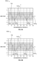
- FIGS. 8A to 8D illustrate exemplary graphs of a waveform of a stimulus from the rotor blades 204 on each of the stator vanes 708 at various phases, according to the present disclosure.
- the waveform of the rotor blades 204 is a sinusoidal waveform.
- FIG. 8A illustrates a graph 800a of the waveform of the rotor blades 204 at an initial condition (0° phase).
- FIG. 8B illustrates a graph 800b of the waveform of the rotor blades 204 at a 30° phase shift.
- FIG. 8C illustrates a graph 800c of the waveform of the rotor blades 204 at a 60° phase shift.
- FIGS. 8A to 8D illustrates a graph 800d of the waveform of the rotor blades 204 at a 90° phase shift.
- the stimulus from the rotor blades 204 is represented by a sine wave as the rotor blades 204 rotate
- the stator vanes 708 are represented by squares at various circumferential positions of the stator assembly 706 ( FIG. 7 ).
- FIGS. 8A to 8D show the uniform spacing US, the first non-uniform gap NUG 1 , the second non-uniform gap NUG 2 , the third non-uniform gap NUG 3 , and the fourth non-uniform gap NUG 4 .
- FIGS. 8A to 8D illustrate a third example of the at least one pair of non-uniform gaps.
- the third example provides exemplary values of the first pair of non-uniform gaps NUG 1 , NUG 2 , the second pair of non-uniform gaps NUG 3 , NUG 4 , and the uniform spacing US.
- the rotor assembly 202 includes eighteen rotor blades 204 and the stator assembly 706 includes sixteen stator vanes 708.
- the uniform spacing US is determined based on relationship (4), above. Thus, if the integer i is five, NB is eighteen, and NS is sixteen, the uniform spacing US is approximately twenty-five degrees (25°) based on relationship (4).
- the first non-uniform gap NUG 1 equals the second non-uniform gap NUG 2
- the first non-uniform gap NUG 1 and the second non-uniform gap NUG 2 are selected to be approximately fifteen degrees (15°).
- the third non-uniform gap NUG 3 and the fourth non-uniform gap NUG 4 are determined by relationship (3), above, and the third non-uniform gap NUG 3 equals the second non-uniform gap NUG 4 .
- N B is eighteen
- Ns is sixteen
- the uniform spacing US is approximately 25°
- the first non-uniform gap NUG 1 is approximately 15°
- the third non-uniform gap NUG 3 and the fourth non-uniform gap NUG4 are approximately fifteen degrees (15°) per relationship (3).
- the vibration response on the stator vanes 708 is balanced about the X-axis and the Y-axis.
- the vibration response of the eight stator vanes 708 that are positioned between 0° to 180° on the stator assembly 706 is equal to the vibration response of the eight stator vanes 708 that are positioned between 180° to 360° on the stator assembly 706 as the phase changes from the initial condition (graph 800a in FIG. 8D ) to the 90° phase shift (graph 800d in FIG. 8D ) about both the X-axis and the Y-axis.
- the vibration response of the eight stator vanes 708 that are positioned between 0° to 180° on the stator assembly 706 is repeated by the vibration response of the eight stator vanes 708 that are positioned between 180° to 360° about the X-axis and the Y-axis such that the vibration response of the stator vanes 708 is balanced about the X-axis and the Y-axis.
- the stator assembly 706 having at least one pair of non-uniform gaps including a first pair of non-uniform gaps NUG 1 , NUG 2 that are equal and a second pair of non-uniform gaps NUG 3 , NUG 4 eliminates both the zero nodal diameter system response and the one nodal diameter system response.
- stator assembly 706 having at least one pair of non-uniform gaps including a first pair of non-uniform gaps NUG 1 , NUG 2 and a second pair of non-uniform gaps NUG 3 , NUG 4 prevents the zero nodal diameter system response (e.g., prevents the unbalanced force) and the one nodal diameter system response (e.g., prevents the unbalanced moment) through the turbine engine 10 ( FIG. 1 ).
- FIGS. 9A to 9D illustrate exemplary graphs of a waveform of a stimulus from the rotor blades 204 on each of the stator vanes 708 at various phases, according to another embodiment.
- the waveform of the rotor blades 204 is a sinusoidal waveform.
- FIG. 9A illustrates a graph 900a of a waveform of the rotor blades 204 at an initial condition (0° phase).
- FIG. 9B illustrates a graph 900b of the waveform of the rotor blades 204 at a 30° phase shift.
- FIG. 9C illustrates a graph 900c of the waveform of the rotor blades 204 at a 60° phase shift.
- FIG. 9A illustrates a graph 900a of a waveform of the rotor blades 204 at an initial condition (0° phase).
- FIG. 9B illustrates a graph 900b of the waveform of the rotor blades 204 at a 30° phase shift.
- FIGS. 9D illustrates a graph 900d of the waveform of the rotor blades 204 at a 90° phase shift.
- the waveform of the rotor blades 204 is represented by a sine wave as the rotor blades 204 rotate, and the stator vanes 708 are represented by squares at various circumferential positions of the stator assembly 706 ( FIG. 7 ).
- FIGS. 9A to 9D show the uniform spacing US, the first non-uniform gap NUG 1 , the second non-uniform gap NUG 2 , the third non-uniform gap NUG 3 , and the fourth non-uniform gap NUG 4 .
- FIGS. 9A to 9D illustrate a fourth example of the at least one pair of non-uniform gaps.
- the fourth example provides exemplary values of the first pair of non-uniform gaps NUG 1 , NUG 2 , the second pair of non-uniform gaps NUG 3 , NUG 4 , and the uniform spacing US.
- the rotor assembly 202 includes eighteen rotor blades 204 and the stator assembly 706 includes sixteen stator vanes 708.
- the first non-uniform gap NUG 1 equals the second non-uniform gap NUG 2 and is selected to be approximately fifty-five degrees (55°).
- the uniform spacing US is determined based on relationship (5), above.
- the uniform spacing US is approximately eighteen point three degrees 18.3° based on relationship (5).
- the third non-uniform gap NUG 3 and the fourth non-uniform gap NUG 4 are determined by relationship (3), above, and the third non-uniform gap NUG 3 equals the second non-uniform gap NUG 4 .
- N B is eighteen
- Ns is sixteen
- the first non-uniform gap NUG 1 is approximately 55°
- the uniform spacing US is approximately 18.3°
- the third non-uniform gap NUG 3 and the fourth non-uniform gap NUG4 are approximately fifteen degrees (15°) per relationship (3).
- the vibration response on the stator vanes 708 is balanced about the X-axis and the Y-axis.
- the vibration response of the eight stator vanes 708 that are positioned between 0° to 180° on the stator assembly 706 is equal to the vibration response of the eight stator vanes 708 that are positioned between 180° to 360° on the stator assembly 706 as the phase changes from the initial condition (graph 900a in FIG. 9D ) to the 90° phase shift (graph 900d in FIG. 9D ) about both the X-axis and the Y-axis.
- the vibration response of the eight stator vanes 708 that are positioned between 0° to 180° on the stator assembly 706 is repeated by the vibration response of the eight stator vanes 708 that are positioned between 180° to 360° about the X-axis and the Y-axis such that the vibration response of the stator vanes 708 is balanced about the X-axis and the Y-axis.
- the stator assembly 706 having at least one pair of non-uniform gaps including a first pair of non-uniform gaps NUG 1 , NUG 2 that are equal and a second pair of non-uniform gaps NUG 3 , NUG 4 eliminates both the zero nodal diameter system response and the one nodal diameter system response.
- the stator assembly 706 having at least one pair of non-uniform gaps including a first pair of non-uniform gaps NUG 1 , NUG 2 and a second pair of non-uniform gaps NUG 3 , NUG 4 prevents the zero nodal diameter system response (e.g., prevents the unbalanced force) and the one nodal diameter system response (e.g., prevents the unbalanced moment) through the turbine engine 10 ( FIG. 1 ).
- the present disclosure provides a stator assembly having at least one pair of non-uniform gaps between adjacent stator vanes to eliminate, or to prevent, at least one of the zero nodal diameter system response (e.g., the unbalanced force) or the one nodal diameter system response (e.g., the unbalanced moment).
- the at least one pair of non-uniform gaps are opposing non-uniform gaps such that the at least one pair of non-uniform gaps is separated by one hundred eighty degrees (180°).
- the at least one pair of opposing non-uniform gaps of the stator assembly includes a first non-uniform gap between a first group of two adjacent stator vanes and a second non-uniform gap between a second group of two adjacent stator vanes.
- the first non-uniform gap is different than the second non-uniform gap to eliminate, or to prevent, the zero nodal diameter system response.
- the first non-uniform gap is equal to the second non-uniform gap to eliminate, or to prevent, the one nodal diameter system response.
- the at least one pair of opposing non-uniform gaps includes two pairs of opposing non-uniform opposing gaps to eliminate, or to prevent, both the zero nodal diameter system response and the one nodal diameter system response.
- the present disclosure provides for eliminating, or preventing, at least one of the zero nodal diameter system response (e.g., the unbalanced force) or the one nodal diameter system response (e.g., the unbalanced moment).
- a rotor system for a turbine engine having a longitudinal centerline axis and comprises a rotor assembly including a plurality of rotor blades, the plurality of rotor blades rotating about the longitudinal centerline axis, and a stator assembly including a plurality of stator vanes arranged circumferentially about the stator assembly and including at least one pair of non-uniform gaps between adjacent stator vanes, the plurality of stator vanes comprises a first group of stator vanes having a first non-uniform gap of the at least one pair of non-uniform gaps between adjacent stator vanes of the first group of stator vanes, and a second group of stator vanes having a second non-uniform gap of the at least one pair of non-uniform gaps between adjacent stator vanes of the second group of stator vanes, the first non-uniform gap being positioned 180° from the second non-uniform gap, and a third group of stator vanes having a uniform spacing
- stator assembly being positioned downstream of the rotor assembly.
- the at least one pair of non-uniform gaps being sized to prevent at least one of a zero nodal diameter system response or a one nodal diameter response.
- the air directed through the plurality of stator vanes causes a vibration response on the plurality of stator vanes, and the at least one pair of non-uniform gaps balances the vibration response on the plurality of stator vanes about the stator assembly.
- the first group of stator vanes includes two stator vanes of the plurality of stator vanes
- the second group of stator vanes includes two stator vanes of the plurality of stator vanes.
- the first non-uniform gap being defined by a number of rotor blades of the plurality of rotor blades, a number of stator vanes of the plurality of stator vanes, and the uniform spacing.
- the second non-uniform gap being defined by the number of stator vanes of the plurality of stator vanes, the uniform spacing, and the first non-uniform gap.
- the rotating shaft being at least one of a fan shaft, a high-pressure shaft, or a low-pressure shaft.
- the at least one pair of non-uniform gaps includes at least two pairs of non-uniform gaps including a first pair of non-uniform gaps and a second pair of non-uniform gaps.
- the second pair of non-uniform gaps including a third non-uniform gap and a fourth non-uniform gap.
- the third non-uniform gap being positioned at a three o'clock position of the stator assembly, and the fourth non-uniform gap being positioned at a nine o'clock position of the stator assembly.
- the at least one pair of non-uniform gaps being defined by an angular measurement.
- the angular measurement being defined by a spacing measured with respect to an angle between adjacent stator vanes.
- the first non-uniform gap being given by 180 ° 180 ° N B ⁇ N S ⁇ 2 2 US, N B being a number of rotor blades of the plurality of rotor blades, Ns being a number of stator vanes of the plurality of stator vanes, and US being the uniform spacing.
- the second non-uniform gap being given by 360° - NUG 1 - (N S - 2)US, NUG 1 being the first non-uniform gap.
- a turbine engine having a longitudinal centerline axis and comprises a rotating shaft, the rotating shaft being at least one of a fan shaft, a high-pressure shaft, or a low-pressure shaft
- a rotor system comprises a rotor assembly including a plurality of rotor blades, the rotor assembly coupled to the rotating shaft and the plurality of rotor blades rotating about the longitudinal centerline axis, and a stator assembly including a plurality of stator vanes arranged circumferentially about the stator assembly and including at least one pair of non-uniform gaps between adjacent stator vanes, the plurality of stator vanes comprises a first group of stator vanes having a first non-uniform gap of the at least one pair of non-uniform gaps between adjacent stator vanes of the first group of stator vanes, a second group of stator vanes having a second non-uniform gap of the at least one pair of non-uniform gaps between adjacent stator vanes of the second group of stator vanes
- stator assembly being positioned downstream of the rotor assembly.
- the at least one pair of non-uniform gaps being sized to prevent at least one of a zero nodal diameter system response or a one nodal diameter response.
- the air directed through the plurality of stator vanes causes a vibration response on the plurality of stator vanes, and the at least one pair of non-uniform gaps balances the vibration response on the plurality of stator vanes about the stator assembly.
- the first group of stator vanes includes two stator vanes of the plurality of stator vanes
- the second group of stator vanes includes two stator vanes of the plurality of stator vanes
- the first non-uniform gap being defined by a number of rotor blades of the plurality of rotor blades, a number of stator vanes of the plurality of stator vanes, and the uniform spacing.
- the second non-uniform gap being defined by the number of stator vanes of the plurality of stator vanes, the uniform spacing, and the first non-uniform gap.
- the at least one pair of non-uniform gaps being positioned at a twelve o'clock position and a six o'clock position of the stator assembly.
- the at least one pair of non-uniform gaps includes at least two pairs of non-uniform gaps including a first pair of non-uniform gaps and a second pair of non-uniform gaps.
- the first pair of non-uniform gaps being spaced 90° from the second pair non-uniform gaps.
- the second pair of non-uniform gaps including a third non-uniform gap and a fourth non-uniform gap.
- the third non-uniform gap being positioned at a three o'clock position of the stator assembly, and the fourth non-uniform gap being positioned at a nine o'clock position of the stator assembly.
- the at least one pair of non-uniform gaps being defined by an angular measurement.
- the angular measurement being defined by a spacing measured with respect to an angle between adjacent stator vanes.
- the first non-uniform gap being given by 180 ° + 180 ° N B ⁇ N S ⁇ 2 2 US, N B being a number of rotor blades of the plurality of rotor blades, Ns being a number of stator vanes of the plurality of stator vanes, and US being the uniform spacing.
- the second non-uniform gap being given by 360° - NUG 1 - (N S - 2)US, NUG 1 being the first non-uniform gap.
- the uniform spacing being different than the at least one pair of non-uniform gaps.
- the turbine engine of any preceding clause the uniform spacing being determined based on if there were a same number of stator vanes as the number of rotor blades.
- the turbine engine of any preceding clause the uniform spacing being determined based on if there were one less stator vane than the number of rotor blades.
Landscapes
- Engineering & Computer Science (AREA)
- Mechanical Engineering (AREA)
- General Engineering & Computer Science (AREA)
- Structures Of Non-Positive Displacement Pumps (AREA)
Applications Claiming Priority (1)
| Application Number | Priority Date | Filing Date | Title |
|---|---|---|---|
| US18/456,671 US12366176B2 (en) | 2023-08-28 | 2023-08-28 | Rotor system for a turbine engine |
Publications (1)
| Publication Number | Publication Date |
|---|---|
| EP4524367A1 true EP4524367A1 (de) | 2025-03-19 |
Family
ID=91967020
Family Applications (1)
| Application Number | Title | Priority Date | Filing Date |
|---|---|---|---|
| EP24190396.2A Pending EP4524367A1 (de) | 2023-08-28 | 2024-07-23 | Rotorsystem für einen turbinenmotor |
Country Status (3)
| Country | Link |
|---|---|
| US (2) | US12366176B2 (de) |
| EP (1) | EP4524367A1 (de) |
| CN (1) | CN119531955A (de) |
Families Citing this family (1)
| Publication number | Priority date | Publication date | Assignee | Title |
|---|---|---|---|---|
| US12497905B1 (en) * | 2024-06-12 | 2025-12-16 | Rtx Corporation | Non-uniform and bi-tri stator spacing for swirl recovery vane (SRV) open rotor engines |
Citations (4)
| Publication number | Priority date | Publication date | Assignee | Title |
|---|---|---|---|---|
| US1534721A (en) * | 1924-04-28 | 1925-04-21 | Aeg | Construction of elastic-fluid turbines to prevent breakage of blades due to vibrations |
| US20120099995A1 (en) * | 2010-10-20 | 2012-04-26 | General Electric Company | Rotary machine having spacers for control of fluid dynamics |
| US20130149135A1 (en) * | 2011-12-07 | 2013-06-13 | Rolls-Royce Plc | Stator vane array |
| US10443626B2 (en) * | 2016-03-15 | 2019-10-15 | General Electric Company | Non uniform vane spacing |
Family Cites Families (20)
| Publication number | Priority date | Publication date | Assignee | Title |
|---|---|---|---|---|
| US3194487A (en) | 1963-06-04 | 1965-07-13 | United Aircraft Corp | Noise abatement method and apparatus |
| US3363419A (en) | 1965-04-27 | 1968-01-16 | Rolls Royce | Gas turbine ducted fan engine |
| US5169288A (en) | 1991-09-06 | 1992-12-08 | General Electric Company | Low noise fan assembly |
| JPH0861001A (ja) | 1994-08-23 | 1996-03-05 | Hitachi Ltd | タービン段落構造 |
| US5681145A (en) | 1996-10-30 | 1997-10-28 | Itt Automotive Electrical Systems, Inc. | Low-noise, high-efficiency fan assembly combining unequal blade spacing angles and unequal blade setting angles |
| US6439838B1 (en) * | 1999-12-18 | 2002-08-27 | General Electric Company | Periodic stator airfoils |
| DE10233033A1 (de) | 2002-07-20 | 2004-01-29 | Rolls-Royce Deutschland Ltd & Co Kg | Strömungs-Arbeits-Maschine mit überhöhtem Rotor-Stator-Kontraktionsverhältnis |
| DE10326533A1 (de) * | 2003-06-12 | 2005-01-05 | Mtu Aero Engines Gmbh | Rotor für eine Gasturbine sowie Gasturbine |
| US7097420B2 (en) * | 2004-04-14 | 2006-08-29 | General Electric Company | Methods and apparatus for assembling gas turbine engines |
| DE102006055869A1 (de) | 2006-11-23 | 2008-05-29 | Rolls-Royce Deutschland Ltd & Co Kg | Schaufelblattdesign für die Lauf- und Leitschaufeln einer Turbomaschine |
| US8043063B2 (en) * | 2009-03-26 | 2011-10-25 | Pratt & Whitney Canada Corp. | Intentionally mistuned integrally bladed rotor |
| US8684685B2 (en) * | 2010-10-20 | 2014-04-01 | General Electric Company | Rotary machine having grooves for control of fluid dynamics |
| US8678752B2 (en) * | 2010-10-20 | 2014-03-25 | General Electric Company | Rotary machine having non-uniform blade and vane spacing |
| US9022721B2 (en) | 2011-10-10 | 2015-05-05 | Wind Power Systems, LLC | Vertical axis wind turbine |
| US20130094942A1 (en) * | 2011-10-12 | 2013-04-18 | Raymond Angus MacKay | Non-uniform variable vanes |
| US10605172B2 (en) | 2013-03-14 | 2020-03-31 | United Technologies Corporation | Low noise turbine for geared gas turbine engine |
| US9890649B2 (en) * | 2016-01-29 | 2018-02-13 | Pratt & Whitney Canada Corp. | Inlet guide assembly |
| GB201808646D0 (en) * | 2018-05-25 | 2018-07-11 | Rolls Royce Plc | Rotor Blade Arrangement |
| FR3127025B1 (fr) | 2021-09-10 | 2024-03-08 | Safran Aircraft Engines | Souplesses dans une turbomachine à réducteur |
| FR3127024B1 (fr) | 2021-09-10 | 2024-03-08 | Safran Aircraft Engines | Souplesses dans une turbomachine à réducteur |
-
2023
- 2023-08-28 US US18/456,671 patent/US12366176B2/en active Active
-
2024
- 2024-07-23 EP EP24190396.2A patent/EP4524367A1/de active Pending
- 2024-08-27 CN CN202411182860.1A patent/CN119531955A/zh active Pending
-
2025
- 2025-07-18 US US19/273,607 patent/US20260092535A1/en active Pending
Patent Citations (4)
| Publication number | Priority date | Publication date | Assignee | Title |
|---|---|---|---|---|
| US1534721A (en) * | 1924-04-28 | 1925-04-21 | Aeg | Construction of elastic-fluid turbines to prevent breakage of blades due to vibrations |
| US20120099995A1 (en) * | 2010-10-20 | 2012-04-26 | General Electric Company | Rotary machine having spacers for control of fluid dynamics |
| US20130149135A1 (en) * | 2011-12-07 | 2013-06-13 | Rolls-Royce Plc | Stator vane array |
| US10443626B2 (en) * | 2016-03-15 | 2019-10-15 | General Electric Company | Non uniform vane spacing |
Also Published As
| Publication number | Publication date |
|---|---|
| US20250075634A1 (en) | 2025-03-06 |
| US20260092535A1 (en) | 2026-04-02 |
| US12366176B2 (en) | 2025-07-22 |
| CN119531955A (zh) | 2025-02-28 |
Similar Documents
| Publication | Publication Date | Title |
|---|---|---|
| US11859516B2 (en) | Gas turbine engine with third stream | |
| US12085024B2 (en) | High fan tip speed engine | |
| US11480063B1 (en) | Gas turbine engine with inlet pre-swirl features | |
| US10508546B2 (en) | Turbomachine with alternatingly spaced turbine rotor blades | |
| US10738617B2 (en) | Turbomachine with alternatingly spaced turbine rotor blades | |
| US10914194B2 (en) | Turbomachine with alternatingly spaced turbine rotor blades | |
| US10823000B2 (en) | Turbomachine with alternatingly spaced turbine rotor blades | |
| US10781717B2 (en) | Turbomachine with alternatingly spaced turbine rotor blades | |
| US11098592B2 (en) | Turbomachine with alternatingly spaced turbine rotor blades | |
| US20190085721A1 (en) | Turbomachine with alternatingly spaced turbine rotor blades | |
| US12065989B2 (en) | Gas turbine engine with third stream | |
| US11834954B2 (en) | Gas turbine engine with third stream | |
| US20260092535A1 (en) | Rotor system for a turbine engine | |
| US11913352B2 (en) | Cover plate connections for a hollow fan blade | |
| US12410715B2 (en) | Rotor blade system for turbine engines | |
| US12410722B2 (en) | Circumferential row of vanes for a gas turbine engine and having non-uniform vane spacing | |
| EP4365425A1 (de) | Gasturbinenmotor mit drittem strom | |
| US20230080798A1 (en) | Gas turbine engine with third stream | |
| US11859515B2 (en) | Gas turbine engines with improved guide vane configurations | |
| US20250305447A1 (en) | Compact core arrangement for high bypass ratio gas turbine engine architecture | |
| US12320304B2 (en) | Gas turbine engine including a compressor bleed air system | |
| EP4144980A1 (de) | Gasturbinentriebwerk mit einem dritten strom | |
| US20250075623A1 (en) | Rotor blades with passageways | |
| US20200300175A1 (en) | Gearbox for a turbomachine with alternatingly spaced rotor blades |
Legal Events
| Date | Code | Title | Description |
|---|---|---|---|
| PUAI | Public reference made under article 153(3) epc to a published international application that has entered the european phase |
Free format text: ORIGINAL CODE: 0009012 |
|
| STAA | Information on the status of an ep patent application or granted ep patent |
Free format text: STATUS: THE APPLICATION HAS BEEN PUBLISHED |
|
| AK | Designated contracting states |
Kind code of ref document: A1 Designated state(s): AL AT BE BG CH CY CZ DE DK EE ES FI FR GB GR HR HU IE IS IT LI LT LU LV MC ME MK MT NL NO PL PT RO RS SE SI SK SM TR |
|
| STAA | Information on the status of an ep patent application or granted ep patent |
Free format text: STATUS: REQUEST FOR EXAMINATION WAS MADE |
|
| 17P | Request for examination filed |
Effective date: 20250909 |