EP4524419A1 - Dispositif de purification d'air - Google Patents
Dispositif de purification d'air Download PDFInfo
- Publication number
- EP4524419A1 EP4524419A1 EP23196696.1A EP23196696A EP4524419A1 EP 4524419 A1 EP4524419 A1 EP 4524419A1 EP 23196696 A EP23196696 A EP 23196696A EP 4524419 A1 EP4524419 A1 EP 4524419A1
- Authority
- EP
- European Patent Office
- Prior art keywords
- air
- air guide
- cleaning device
- air cleaning
- section
- Prior art date
- Legal status (The legal status is an assumption and is not a legal conclusion. Google has not performed a legal analysis and makes no representation as to the accuracy of the status listed.)
- Granted
Links
Images


Classifications
-
- F—MECHANICAL ENGINEERING; LIGHTING; HEATING; WEAPONS; BLASTING
- F16—ENGINEERING ELEMENTS AND UNITS; GENERAL MEASURES FOR PRODUCING AND MAINTAINING EFFECTIVE FUNCTIONING OF MACHINES OR INSTALLATIONS; THERMAL INSULATION IN GENERAL
- F16D—COUPLINGS FOR TRANSMITTING ROTATION; CLUTCHES; BRAKES
- F16D65/00—Parts or details
- F16D65/0031—Devices for retaining friction material debris, e.g. dust collectors or filters
-
- B—PERFORMING OPERATIONS; TRANSPORTING
- B01—PHYSICAL OR CHEMICAL PROCESSES OR APPARATUS IN GENERAL
- B01D—SEPARATION
- B01D46/00—Filters or filtering processes specially modified for separating dispersed particles from gases or vapours
- B01D46/0039—Filters or filtering processes specially modified for separating dispersed particles from gases or vapours with flow guiding by feed or discharge devices
- B01D46/0041—Filters or filtering processes specially modified for separating dispersed particles from gases or vapours with flow guiding by feed or discharge devices for feeding
- B01D46/0045—Filters or filtering processes specially modified for separating dispersed particles from gases or vapours with flow guiding by feed or discharge devices for feeding by using vanes
-
- B—PERFORMING OPERATIONS; TRANSPORTING
- B01—PHYSICAL OR CHEMICAL PROCESSES OR APPARATUS IN GENERAL
- B01D—SEPARATION
- B01D46/00—Filters or filtering processes specially modified for separating dispersed particles from gases or vapours
- B01D46/10—Particle separators, e.g. dust precipitators, using filter plates, sheets or pads having plane surfaces
-
- B—PERFORMING OPERATIONS; TRANSPORTING
- B60—VEHICLES IN GENERAL
- B60H—ARRANGEMENTS OF HEATING, COOLING, VENTILATING OR OTHER AIR-TREATING DEVICES SPECIALLY ADAPTED FOR PASSENGER OR GOODS SPACES OF VEHICLES
- B60H3/00—Other air-treating devices
- B60H3/06—Filtering
- B60H3/0658—Filter elements specially adapted for their arrangement in vehicles
-
- B—PERFORMING OPERATIONS; TRANSPORTING
- B60—VEHICLES IN GENERAL
- B60T—VEHICLE BRAKE CONTROL SYSTEMS OR PARTS THEREOF; BRAKE CONTROL SYSTEMS OR PARTS THEREOF, IN GENERAL; ARRANGEMENT OF BRAKING ELEMENTS ON VEHICLES IN GENERAL; PORTABLE DEVICES FOR PREVENTING UNWANTED MOVEMENT OF VEHICLES; VEHICLE MODIFICATIONS TO FACILITATE COOLING OF BRAKES
- B60T17/00—Component parts, details, or accessories of power brake systems not covered by groups B60T8/00, B60T13/00 or B60T15/00, or presenting other characteristic features
- B60T17/002—Air treatment devices
Definitions
- the invention relates to an air cleaning device like a brake dust filter device for a disc brake assembly. Furthermore, the invention relates to a vehicle with an air cleaning device.
- EP 2 522 876 A1 describes a disc brake assembly which includes a rotor that is turned by motion of a vehicle; a caliper and brake pads attached to the caliper; the rotor having an inside face periphery, an outside face periphery and an outside diameter periphery; a filter disposed within a shroud, the shroud being disposed proximate to the rotor so as to cover at least about 70% of at least one of the inside face and the outside face peripheries wherein the shroud houses a radially inner filter and a radially outer filter, and wherein when said vehicle is in motion, rotation of said rotor moves brake dust into said radial inner filter and said radially outer filter.
- WO 2018/134313 A1 discloses an ambient air purification device in a road vehicle designed to remove fine dust from the ambient air.
- the ambient air purification device has a filter element and is arranged transversely to a longitudinal axis of the vehicle in an outer region of the vehicle. It is housed in an installation space provided by a vehicle frame.
- an air cleaning device which can be used in vehicles, in particular in motor vehicles, to clean air which is released in the environment or which is used in the vehicle for further purpose.
- the air cleaning device is designed as a brake dust filter device for collecting collect dust and particles which are produced by friction in a disc brake assembly when the vehicle brake is actuated.
- the air cleaning device includes a filter element and an air guide region in flow connection with the filter element.
- an adjustable air guide flap is arranged for adjusting the airflow passing the air guide region.
- the air guide flap is mounted on a pivot joint and can be turned about the rotational axis of the pivot joint between a closed position with reduced or zero air flow and an open position with maximum air flow.
- the pivot joint is arranged in a housing of the air guide region which can be part of the housing of the air cleaning device.
- the air guide flap has a closing section and an opening section which are connected with each other.
- the pivot joint is arranged between the closing section and the opening section of the air guide flap.
- the closing section forms an air resistance surface for the air flow passing through the air guide region.
- the air guide flap is able to react to the pressure exerted by the air flow.
- the air guide flap When hitting the closing section while standing in its open position the air guide flap turns about the rotational axis of the pivot joint if the velocity and hence the pressure of the air flow is high enough.
- the air guide flap turns from the open position into the closed position so that only a smaller air flow or no air flow is allowed to pass the air guide region.
- the air guide flap Depending on the pressure of the air flow, the air guide flap turns into a completely closed position or into an intermediate position between the closed position and a maximum open position.
- "Open position" includes all positions of the air guide flap which have an open cross-sectional area greater than the cross-sectional area in the closed position in which the open cross-sectional area is either zero or a minimum.
- the air guide flap is moved by the air flow hitting the closing section.
- the air flow may depend on the velocity of the vehicle.
- the air flow hits the closing section of the air guide flap with the same speed as the vehicle speed and turns the air guide flap into the closed position so that the filter element which is arranged downstream of the air guide flap receives no air or only a minimum of air for filtration purpose.
- the air flow passing the air guide region through the open-air guide flap and the filter element is a maximum.
- the opening section of the air guide flap has a greater mass than the closing section so that in the closed position a torque directed into the open position acts on the air guide flap.
- the air guide flap remains in its open position.
- the air guide flap turns from the closed position into the open position when the air flow hitting the closing section exerts a torque on the air guide flap which is lower than the torque created of the greater mass of the opening section.
- the air guide flap will only turn from the open position into the closed position when the air flow hitting the closing section exerts a torque on the air guide flap which is higher than the torque created of the greater mass of the opening section.
- the opening section and the closing section are each rectilinear and have a common longitudinal axis.
- the opening section and the closing section may be configured as a one-piece element.
- the closing section has a greater length than the opening section which enhances the ability of the closing section to form an air resistance surface for the air flow.
- the closing section is not longer than the opening section but has a cross-sectional design which increases the air resistance, for example a convex cross-sectional design.
- the closing section is longer than the opening section and also has a cross-sectional design which increases the air resistance. The air flow hits the closing section and pushes the air guide flap into the closed position.
- an angular end part is formed at the opening section which lies at an angle greater than zero to the closing section, preferably in a value range from 30° to 60°.
- the angular end part forms an air resistance surface in the air flow in a way that stabilizes the closed position of the air guide flap even when the closing section of the air guide flap lies parallel to the direction of the air flow without providing resistance. It is beneficial that the straight part of the closing section is longer than the straight part of the opening section without the angular end part.
- the opening section is supported by a stopper in the open position, the stopper limiting the opening movement of the air guide flap.
- the stopper can be placed in the housing of the air guide region. It is advantageous that the stopper limits the air guide flap position to a maximum open position which allows a maximum air flow passing the air guide flap.
- the closing section is supported by another stopper in the closed position, the stopper limiting the closing movement of the air guide flap.
- This stopper can also be placed in the housing of the air guide region. It is advantageous that this stopper keeps the air guide flap in such a closed position that the air guide flap lies parallel to the direction of the air flow.
- the air guide region is designed as an air supply region which is placed upstream of the filter element.
- the air supply region is the air intake section of the air cleaning device.
- the air supply region receives an air flow which has the velocity of the vehicle.
- the air guide region is designed as the outlet of the air cleaning device, the air guide flap controlling the outlet air flow downstream the filter element.
- the air guide flap has one or several openings which allow passing a reduced air flow.
- the minimum air flow depends on the size and the number of openings in the air guide flap.
- the openings can be arranged in the opening section. However, it is also possible to arrange the openings in the closing section or both in the closing and the opening section.
- air guide flaps are arranged in the air guide region.
- the air guide flaps may be arranged next to each other over the width/and or over a part of the length of the air guide region. It is advantageous that all air guide flaps are designed identically. Alternatively, only one air guide flap is arranged in the air guide region.
- the air cleaning device is designed as a passive device without actuator.
- the movement of the air guide flap is solely accomplished by the air flow and torques based on the center of gravity and the position of the pivot joint.
- the air cleaning device is designed as an active device with an actuator for adjusting the air guide flap.
- the invention also refers to a vehicle with an aforementioned air cleaning device.
- vehicle is preferably a land vehicle, e.g. a passenger car, a truck, a construction vehicle or an agricultural vehicle.
- the air cleaning device can be arranged on the underbody of the vehicle.
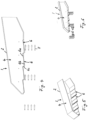
- the air cleaning device 1 includes a housing 2 and a filter element 3 ( fig. 1 ) which is accommodated in the housing 2. Upstream of the filter element 2 the housing 2 includes an air supply region 4 and an inlet opening 5 for supplying ambient air to the filter element 3.
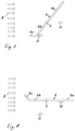
- the housing 2 In the inlet opening 5 several air guide flaps 6 are arranged which are pivotally supported at pivot joints 7 ( fig. 7, 8 ) and can be pivoted between an open position shown in fig. 1, 2, 3 , 7 , 11 and 12 and a closed position shown in fig. 4, 5, 6 , 8 , 9 and 10 .
- the axis of the pivot joints is perpendicular to an air flow depicted with numeral 8.
- the pivot joints 7 may be part of the housing 2.
- air flow 8 can pass the air guide flaps 6 and enter the air supply region 4 where the air flow 8 is guided to the filter element 3 for purifying.
- Air guide flaps 6 stand in the open position when the air flow 8 is low, e.g. when the car is standing or travelling at low speed.
- air flow 8 is reduced to a minimum or even to zero.
- the closed position corresponds to high velocity of the air flow 8. Hence, no ambient air or only a small amount of ambient air can enter the air supply region 4 of the housing 2 and hit the filter element 3.
- Each air guide flap 6 consists of a closing section 6a and an opening section 6b which are each rectilinear and have a common longitudinal axis.
- the closing section 6a and the opening section 6b are configured as a one-piece element with the pivot joint 7 being arranged between both sections 6a, 6b and providing a rotation axis for the air guide flap 6 for rotating between the open position as depicted in fig. 7 and the closed position as depicted in fig. 8 .
- the opening section 6b has a slightly greater mass than the closing section 6a. Consequently, a torque directed into the open position acts on the air guide flap 6. Hence, without an ambient force acting on the air guide flap 6 it will either turn into the open position in case that it is in the closed position, or it will remain in the open position.
- An angular end part 6c is formed at the opening section 6b, the angular end part 6c being part of the opening section 6b.
- the angular end part 6c is integral with the opening section 6b.
- the closing section 6a and the opening section 6b lie in the inlet opening 5 and seal the inlet opening 5 to prevent the air flow 8 from entering the air supply region 4.
- the angular end part 6c is in an angular position to the air flow 8 which streams along the bottom side of the housing 2.
- the air flow 8 hits the angular end part 6c in a way that the pressure of the air flow 8 pushes the air guide flap 6 into the closed position, thus stabilizing the air guide flap 6 in the closed position.
- the air guide flap 6 turns into the open position again.
- each air guide flap 6 being rotatably mounted at a pivot joint 7 so that the air guide flaps 6 can be turned independently from each other. All air guide flaps 6 are designed identically. As depicted in fig. 6 , it may be expedient to arrange additional air guide flaps 6 in the transverse direction which is perpendicular to the length of the inlet opening 5.
Landscapes
- Chemical & Material Sciences (AREA)
- Chemical Kinetics & Catalysis (AREA)
- Engineering & Computer Science (AREA)
- General Engineering & Computer Science (AREA)
- Mechanical Engineering (AREA)
- Air-Flow Control Members (AREA)
- Filtering Of Dispersed Particles In Gases (AREA)
Priority Applications (1)
| Application Number | Priority Date | Filing Date | Title |
|---|---|---|---|
| EP23196696.1A EP4524419B1 (fr) | 2023-09-12 | 2023-09-12 | Dispositif de purification d'air |
Applications Claiming Priority (1)
| Application Number | Priority Date | Filing Date | Title |
|---|---|---|---|
| EP23196696.1A EP4524419B1 (fr) | 2023-09-12 | 2023-09-12 | Dispositif de purification d'air |
Publications (2)
| Publication Number | Publication Date |
|---|---|
| EP4524419A1 true EP4524419A1 (fr) | 2025-03-19 |
| EP4524419B1 EP4524419B1 (fr) | 2026-04-01 |
Family
ID=88018035
Family Applications (1)
| Application Number | Title | Priority Date | Filing Date |
|---|---|---|---|
| EP23196696.1A Active EP4524419B1 (fr) | 2023-09-12 | 2023-09-12 | Dispositif de purification d'air |
Country Status (1)
| Country | Link |
|---|---|
| EP (1) | EP4524419B1 (fr) |
Citations (7)
| Publication number | Priority date | Publication date | Assignee | Title |
|---|---|---|---|---|
| KR100807813B1 (ko) * | 2007-02-07 | 2008-02-27 | 최대식 | 차량 장착용 대기정화장치 |
| EP2522876A1 (fr) | 2008-10-20 | 2012-11-14 | Joseph Gelb | Ensemble frein à disque |
| US20160105996A1 (en) * | 2013-05-22 | 2016-04-14 | Stego-Holding Gmbh | Fan holder for a fan, in particular of a switch cabinet |
| WO2018134313A1 (fr) | 2017-01-18 | 2018-07-26 | Mann+Hummel Gmbh | Véhicule routier comprenant un dispositif d'épuration d'air ambiant, dispositif d'épuration d'air ambiant et élément filtrant |
| WO2019245220A1 (fr) * | 2018-06-19 | 2019-12-26 | 김상겸 | Dispositif de purification d'air monté sur véhicule |
| US20230016203A1 (en) * | 2019-12-19 | 2023-01-19 | Highly Marelli Japan Corporation | Vehicle air-conditioning device |
| US20230233974A1 (en) * | 2022-01-11 | 2023-07-27 | Mahle International Gmbh | Modular filter system |
-
2023
- 2023-09-12 EP EP23196696.1A patent/EP4524419B1/fr active Active
Patent Citations (7)
| Publication number | Priority date | Publication date | Assignee | Title |
|---|---|---|---|---|
| KR100807813B1 (ko) * | 2007-02-07 | 2008-02-27 | 최대식 | 차량 장착용 대기정화장치 |
| EP2522876A1 (fr) | 2008-10-20 | 2012-11-14 | Joseph Gelb | Ensemble frein à disque |
| US20160105996A1 (en) * | 2013-05-22 | 2016-04-14 | Stego-Holding Gmbh | Fan holder for a fan, in particular of a switch cabinet |
| WO2018134313A1 (fr) | 2017-01-18 | 2018-07-26 | Mann+Hummel Gmbh | Véhicule routier comprenant un dispositif d'épuration d'air ambiant, dispositif d'épuration d'air ambiant et élément filtrant |
| WO2019245220A1 (fr) * | 2018-06-19 | 2019-12-26 | 김상겸 | Dispositif de purification d'air monté sur véhicule |
| US20230016203A1 (en) * | 2019-12-19 | 2023-01-19 | Highly Marelli Japan Corporation | Vehicle air-conditioning device |
| US20230233974A1 (en) * | 2022-01-11 | 2023-07-27 | Mahle International Gmbh | Modular filter system |
Also Published As
| Publication number | Publication date |
|---|---|
| EP4524419B1 (fr) | 2026-04-01 |
Similar Documents
| Publication | Publication Date | Title |
|---|---|---|
| CN101457688B (zh) | 发动机进气管系统 | |
| US7302967B2 (en) | Reverse flow preventing device and electronic apparatus | |
| CN107264654B (zh) | 车辆用气流控制装置 | |
| JP5004254B2 (ja) | 自動車のためのフロント部分 | |
| US7316420B2 (en) | Water-expelling mudguard for motor vehicles | |
| CN102498005B (zh) | 用于空气排出口的涡旋装置 | |
| JPS6253287A (ja) | 空気案内装置を車体側に設けた自動車 | |
| US7470178B2 (en) | Air-conditioner for vehicle | |
| US11458806B2 (en) | HVAC inlet with ram air and partial recirculation function | |
| EP4524419A1 (fr) | Dispositif de purification d'air | |
| SE448487B (sv) | Turbokompressor | |
| EP3193005B1 (fr) | Système de pre-filtrage pour véhicule | |
| EP3386790B1 (fr) | Système d'admission d'air de combustion actif pour camion, tracteur ou bus | |
| US20180133633A1 (en) | Device for the precipitation of particles from a gas stream | |
| JP6783173B2 (ja) | 作業車 | |
| JP4546628B2 (ja) | 車輪支承ケーシング | |
| CN109203896A (zh) | 一种实现车身高度调节的悬架系统 | |
| EP1630486A2 (fr) | Agencement de soupape à clapet | |
| KR102037998B1 (ko) | 윈드 디플렉터 타입 공기정화 장치 | |
| JP7329591B2 (ja) | 自動車の空力負荷を制御するための調整装置 | |
| JPH0820318A (ja) | ブレーキ冷却構造 | |
| JP3258554B2 (ja) | 自動車用排気消音装置 | |
| US6626142B2 (en) | Intake air rate controlling device for an internal combustion engine | |
| EP1420146A1 (fr) | Générateur de tourbillons pour compresseur radial | |
| KR20250178593A (ko) | 차량용 에어플랩장치 |
Legal Events
| Date | Code | Title | Description |
|---|---|---|---|
| PUAI | Public reference made under article 153(3) epc to a published international application that has entered the european phase |
Free format text: ORIGINAL CODE: 0009012 |
|
| STAA | Information on the status of an ep patent application or granted ep patent |
Free format text: STATUS: THE APPLICATION HAS BEEN PUBLISHED |
|
| AK | Designated contracting states |
Kind code of ref document: A1 Designated state(s): AL AT BE BG CH CY CZ DE DK EE ES FI FR GB GR HR HU IE IS IT LI LT LU LV MC ME MK MT NL NO PL PT RO RS SE SI SK SM TR |
|
| STAA | Information on the status of an ep patent application or granted ep patent |
Free format text: STATUS: REQUEST FOR EXAMINATION WAS MADE |
|
| 17P | Request for examination filed |
Effective date: 20250827 |
|
| GRAP | Despatch of communication of intention to grant a patent |
Free format text: ORIGINAL CODE: EPIDOSNIGR1 |
|
| STAA | Information on the status of an ep patent application or granted ep patent |
Free format text: STATUS: GRANT OF PATENT IS INTENDED |
|
| RIC1 | Information provided on ipc code assigned before grant |
Ipc: F16D 65/00 20060101AFI20251009BHEP |
|
| INTG | Intention to grant announced |
Effective date: 20251030 |
|
| GRAS | Grant fee paid |
Free format text: ORIGINAL CODE: EPIDOSNIGR3 |
|
| GRAA | (expected) grant |
Free format text: ORIGINAL CODE: 0009210 |
|
| STAA | Information on the status of an ep patent application or granted ep patent |
Free format text: STATUS: THE PATENT HAS BEEN GRANTED |
|
| AK | Designated contracting states |
Kind code of ref document: B1 Designated state(s): AL AT BE BG CH CY CZ DE DK EE ES FI FR GB GR HR HU IE IS IT LI LT LU LV MC ME MK MT NL NO PL PT RO RS SE SI SK SM TR |
|
| REG | Reference to a national code |
Ref country code: CH Ref legal event code: F10 Free format text: ST27 STATUS EVENT CODE: U-0-0-F10-F00 (AS PROVIDED BY THE NATIONAL OFFICE) Effective date: 20260401 Ref country code: GB Ref legal event code: FG4D |
|
| REG | Reference to a national code |
Ref country code: DE Ref legal event code: R096 Ref document number: 602023014375 Country of ref document: DE |
|
| REG | Reference to a national code |
Ref country code: IE Ref legal event code: FG4D |