EP4524432A1 - Bandage de roue creuse pour engrenage planétaire - Google Patents
Bandage de roue creuse pour engrenage planétaire Download PDFInfo
- Publication number
- EP4524432A1 EP4524432A1 EP23197215.9A EP23197215A EP4524432A1 EP 4524432 A1 EP4524432 A1 EP 4524432A1 EP 23197215 A EP23197215 A EP 23197215A EP 4524432 A1 EP4524432 A1 EP 4524432A1
- Authority
- EP
- European Patent Office
- Prior art keywords
- gear
- ring gear
- bandage
- planetary gear
- planetary
- Prior art date
- Legal status (The legal status is an assumption and is not a legal conclusion. Google has not performed a legal analysis and makes no representation as to the accuracy of the status listed.)
- Withdrawn
Links
Images



Classifications
-
- F—MECHANICAL ENGINEERING; LIGHTING; HEATING; WEAPONS; BLASTING
- F16—ENGINEERING ELEMENTS AND UNITS; GENERAL MEASURES FOR PRODUCING AND MAINTAINING EFFECTIVE FUNCTIONING OF MACHINES OR INSTALLATIONS; THERMAL INSULATION IN GENERAL
- F16H—GEARING
- F16H57/00—General details of gearing
- F16H57/08—General details of gearing of gearings with members having orbital motion
-
- F—MECHANICAL ENGINEERING; LIGHTING; HEATING; WEAPONS; BLASTING
- F03—MACHINES OR ENGINES FOR LIQUIDS; WIND, SPRING, OR WEIGHT MOTORS; PRODUCING MECHANICAL POWER OR A REACTIVE PROPULSIVE THRUST, NOT OTHERWISE PROVIDED FOR
- F03D—WIND MOTORS
- F03D15/00—Transmission of mechanical power
- F03D15/10—Transmission of mechanical power using gearing not limited to rotary motion, e.g. with oscillating or reciprocating members
- F03D15/101—Transmission of mechanical power using gearing not limited to rotary motion, e.g. with oscillating or reciprocating members of the epicyclic or planetary type
-
- F—MECHANICAL ENGINEERING; LIGHTING; HEATING; WEAPONS; BLASTING
- F16—ENGINEERING ELEMENTS AND UNITS; GENERAL MEASURES FOR PRODUCING AND MAINTAINING EFFECTIVE FUNCTIONING OF MACHINES OR INSTALLATIONS; THERMAL INSULATION IN GENERAL
- F16C—SHAFTS; FLEXIBLE SHAFTS; ELEMENTS OR CRANKSHAFT MECHANISMS; ROTARY BODIES OTHER THAN GEARING ELEMENTS; BEARINGS
- F16C2360/00—Engines or pumps
- F16C2360/31—Wind motors
-
- F—MECHANICAL ENGINEERING; LIGHTING; HEATING; WEAPONS; BLASTING
- F16—ENGINEERING ELEMENTS AND UNITS; GENERAL MEASURES FOR PRODUCING AND MAINTAINING EFFECTIVE FUNCTIONING OF MACHINES OR INSTALLATIONS; THERMAL INSULATION IN GENERAL
- F16H—GEARING
- F16H1/00—Toothed gearings for conveying rotary motion
- F16H1/28—Toothed gearings for conveying rotary motion with gears having orbital motion
Definitions
- the invention relates to a planetary gear for a wind turbine driven by a rotor, with at least one first planetary stage rotating in a gear housing about an axis of rotation AD , wherein a ring gear of the planetary stage is formed by a ring gear bandage structurally connected to the gear housing, wherein the planetary gear is connected at least indirectly to a main bearing unit upstream in the torque flow via the ring gear bandage.
- Wind turbines use drive trains in which the torque to be transmitted between the main bearing housing and the gearbox housing is limited by the usable flange area between these two housings.
- the flange area of the gearbox housing is formed by the already highly stressed ring gear bandage with the internal gearing.
- the currently used drive train concepts are reaching their limits in terms of the transmittable torque in view of the demand for higher power density. Compensation measures, such as friction-enhancing surface coatings, are increasingly being exhausted.
- a particular problem is dynamic, pulsating movements that are transmitted via the interface or flange connection from the planetary gear to the main bearing unit, where they can lead to annular wear of the outer bearing shells of the main bearings.
- An intermediate flange located between the main bearing unit and the gearbox housing is currently used to
- the planetary carrier of the first planetary stage must be centered for assembly and transport purposes. This applies particularly to separately transported or delivered main bearing units and transmission units.
- a floating planetary carrier is understood to be indirectly supported via the bearings of the main bearing unit.
- the planetary carrier does not have its own bearing relative to the transmission housing.
- the intermediate flange decouples the ring gear or ring gear bandage of the first planetary stage and the main bearing unit.
- This additional component increases the cost and weight of the entire drive train and also requires two flange connections to fulfill its function.
- the disadvantages include potential leakage opportunities due to micro-movements and the risk of surface disruption in the form of fretting corrosion.
- the transmission of high torques is limited by the usable flange area, and these limits are already being reached. There is a constant need to improve the connection area between the main bearing unit and the gearbox with regard to torque transferability.
- the object of the invention is to show measures that improve torque transmission in the connection area between the main bearing unit and the gearbox.
- One embodiment relates to a planetary gear for a wind turbine driven by a rotor, with at least one first planetary stage rotating in a gear housing about an axis of rotation AD , wherein a ring gear of the planetary stage is formed by a ring gear bandage structurally connected to the gear housing, wherein the ring gear bandage has a plurality of axial bores arranged circumferentially and in at least two radially spaced circumferences for connecting the planetary gear to a main bearing unit arranged upstream in the torque flow, starting from an end face.
- the ring gear bandage can be described as a housing part.
- the ring gear bandage can be designed as a rather soft component, as it is slim due to its large outer diameter and equally large inner diameter.
- the axial bores arranged on two circumferences can also be referred to as rows of bores arranged at different radii.
- the rows of bores are expediently arranged concentrically to one another.
- the terminology "inner row of bores” and "outer row of bores” is appropriate.
- the rows of bores can have the same or a different number of axial bores.
- the axial bores are designed at least partially as through bores. It can also preferably be provided that the axial bores are designed at least partially as threaded bores.
- the end face of the ring gear bandage can also be referred to as the flange face, as it can be used to connect to the mating face of the housing of the main bearing unit.
- the ring gear bandage has a radial wall thickness that can be used to a large extent for force- and friction-locked torque transmission between the main bearing unit and the gearbox housing via the two radially spaced rows of holes. Due to the increased By increasing the annular surface, the number of torque-transmitting pins and/or bolts can be increased, thus improving the necessary frictional transmission capacity. This reduces micromovements in the interface or flange surfaces. Consequently, the formation of fretting corrosion is reduced, thus reducing particle ingress into the gearbox and main bearing unit.
- the increased usable flange area and multi-row bolting and/or pinning allow higher torques to be transmitted without the usual friction-enhancing measures. Furthermore, the radial and tangential moments of resistance at the contact surface are increased. Due to the reduced micromovements, the sealing ring also experiences less movement, increasing its service life. Eliminating the intermediate flange typically used between the main bearing unit and the gearbox housing results in cost savings.
- an intermediate flange also eliminates the negative effects of reduced friction coefficients that arise from repeated disassembly and assembly of the main bearing unit and the gearbox. Another advantage is that conventional heat treatment processes can be retained, as they are not affected by the design changes resulting from the elimination of an intermediate flange. Furthermore, the elimination of an intermediate flange results in a reduction in the tolerance chain and an improvement in the axial runout of the main bearing unit to the gearbox. Finally, assembly is easier, both during initial assembly and when parts are delivered individually, as the resulting reduced weight results in less form deviation.
- the axial bores on the first circumference and the axial bores on the radially spaced second circumference are arranged offset from one another in the circumferential direction. It is then expedient, for example, that an axial bore of one row of bores is arranged radially offset between two axial bores of the other row of bores.
- a running toothing arranged on an inner circumference of the ring gear bandage opens into a tooth run-out in the direction of the end face.
- the axial width of the running toothing remains essentially the same as with conventional ring gear bandages, which are additionally mounted with an intermediate flange.
- the tooth run-out ensures that the axial width of the running toothing does not extend over the entire axial width of the ring gear bandage. Consequently, a certain axial width of the ring gear bandage remains unaffected by the contour of the running toothing, so that the ring gear bandage has the full radial wall thickness between the end face and the tooth run-out.
- the tooth run-out preferably ends at an axial distance from the end face. The tooth run-out is milled or turned during production in order not to extend the resulting grinding time.
- a further preferred embodiment provides for a circumferential free rotation up to the tooth root of the running gear in the transition from the running gear to the gear runout. This circumferential free rotation ensures that no stiffness jump occurs in the transition from the running gear to the gear runout.
- radial bores in an axial region of the ring gear bandage between the free rotation and the end face, several circumferentially arranged radial bores are provided.
- at least three evenly spaced radial bores are provided, wherein these are each arranged in a circumferential region preferably at 8 o'clock, 12 o'clock and 16 o'clock. Screw elements, for example, can be introduced through these radial bores, which are directed radially inward towards the planet carrier of the first planetary stage and center the planet carrier for assembly or transport.
- the cantilevered planet carrier of the first planetary stage to be centered or fixed in the ring gear (non-toothed area) in a local manner without the use of an intermediate flange.
- two radial bores are provided, each arranged in a circumferential area at 9 o'clock and 15 o'clock. Screw or clamping elements can also be provided in these radial bores, which are screwed into both the ring gear bandage and the planet carrier of the first planetary stage in order to use the planet carrier as a pull rod and to compensate for the deformation caused by the gear's own weight when handling the gearbox.
- a wrench flat can be arranged on the outside of the ring gear bandage in a circumferential area at 9 o'clock and 15 o'clock in order to be able to attach a pliers-like tool to the wrench flats, which compensates for the deformation caused by the gear's own weight.
- a drive train for a wind turbine for the torque-transmitting connection of a rotor to a generator comprising a main bearing unit, a main shaft mounted in the main bearing unit, a gearbox driven via the main shaft, and a generator drivingly connected to the gearbox, wherein the gearbox is designed as described.
- a planet carrier of the planetary stage is mounted indirectly via the main shaft relative to the main bearing unit and centered relative to the gearbox housing.
- a wind turbine comprising a rotor flange with a rotor and a generator, wherein a drive train is provided which is held on a machine carrier and connects the rotor flange to the generator, wherein the drive train is designed as described.
- the Figure 1 shows a schematic and not to scale representation of a wind turbine 100 in one possible embodiment.
- the essential element of the wind turbine 100 is a drive train 102, which in this case structurally comprises a rotor flange 104 with a rotor 106, a main bearing unit 108, a gearbox 10, and a generator 112.
- At least the main bearing unit 108 and the generator 112 are supported by a machine support 114 via a tower 116 relative to a ground (not shown).
- the main bearing unit 108 comprises a main shaft 118, which is mounted via an adjusted tapered roller bearing relative to a bearing housing 120 of the main bearing unit 108 so as to be rotatable about an axis of rotation AD .
- the rotor flange 104 and the rotor 106 are held at one end of the main shaft 118.
- the other end of the main shaft 118 is rigidly connected to the gearbox 10 for driving purposes in order to transmit a drive torque generated by the rotor 106 to the gearbox 10.
- the gearbox 10 is designed as a planetary gear with one or more planetary stages.
- the gearbox 10 is drivingly connected to the generator 112 via a generator shaft 124.
- the bearing housing 120 is connected to the gearbox 10 via a flange 126.
- a reaction torque of the gearbox 10 is supported relative to the machine support 114 via the flange 126.
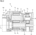
- the Figure 2 shows a section of an assembly of a planetary gear 10 and the main bearing unit 108, as it is shown, for example, in a Figure 1 illustrated wind turbine 100 can be installed. Shown are two planetary stages 14 1 and 14 2 arranged one behind the other, which are arranged in a gear housing 12 so as to rotate about an axis of rotation AD . A third planetary stage, not shown, can also be provided.
- the planetary stages 14 1 and 14 2 are constructed accordingly and each have a planet carrier 16 1 , 16 2 , a ring gear 20 1 , 20 2 , a sun gear 22 1 , 22 2 and a plurality of planet gears 18 1 , 18 2 rotating with the respective planet carrier 16 1 , 16 2 and alternately meshing with the ring gear 20 1 , 20 2 and the sun gear 22 1 , 22 2
- the planet carrier 16 2 of the second planetary stage 14 1 is supported on both sides or one side by bearings 24 on support flanges 26 on the housing side.
- the second planet carrier is held largely centrally in the gear housing 12 of the planetary gear 10 by the bearings 24.
- the sun 22 1 of the first planetary stage 14 1 is connected in a rotationally fixed and rigid manner to the planet carrier 16 2 of the second planetary stage 14 2.
- the planet carrier 16 1 of the first planetary stage 14 1 is not specifically mounted in the housing 12, but after assembly is mounted indirectly via the main bearing unit 108 via a rotationally fixed connection to the main shaft 118.
- the connection of the ring gear 20 1 of the first planetary stage 14 1 , designed as a ring gear bandage, to the bearing housing 120 of the main bearing unit 108 is in the Figure 2 only shown in principle and with the aid of the further figures, in particular a possible design of the ring gear bandage 20 1 is explained, in the use of which a separate intermediate flange between the bearing housing 120 and the gear housing 12 can be dispensed with.
- the ring gear 20 1 of the first planetary stage 14 1 designed as a ring gear bandage, can, as in the Figure 3 shown.
- the ring gear bandage 20 described here has an axial width that is greater than the axial width of a conventional ring gear bandage, which is mounted together with an intermediate flange to the bearing housing 120 of the main bearing unit 108.
- the ring gear bandage 20 described here can be divided in its axial width into a first axial section 48 and a second axial section 50.
- the annular ring gear bandage 20 has an inner circumferential surface 36 and on this, within the first axial section 48, a running gear 38, which in a known manner is in meshing engagement with the planet gears 18 of the respective planetary stage 14.
- a gear runout 40 of the running gear 38 and a substantially unprofiled circumferential region are formed on the inner circumferential surface 36.
- the gear runout 40 consequently ends at an axial distance from an end face 28 of the ring gear bandage 20.
- a free rotation 42 is provided on the inner circumference between the running gear 38 and the gear runout 40. The free rotation 42 extends to a tooth root 44 of the running gear 44 and forms the transition between the first and second axial sections 48, 50.
- the ring gear bandage 20 forms a plurality of axial bores 34 arranged circumferentially and in two radially spaced circumferences 32 1 , 32 2 .
- the axial bores 34 are directed in the direction of the axis of rotation AD or parallel to it.
- the planetary gear 20, in which the ring gear bandage 20 is installed can be connected to a main bearing unit 108 arranged upstream in the torque flow.
- the circumferences 32 1 , 32 2 , on which the axial bores 34 are located, can also be referred to as rows of bores.
- the end face 28 for connecting the main bearing unit 108 is located on the axial end of the ring gear bandage 20 facing away from the running gear 38.
- the second end face, not designated in more detail, at the axial end of the running gear serves to connect the ring gear bandage 20 to the rest of the transmission housing 12, which, however, does not require any further explanation here.
- the axial bores 34 can be designed differently in detail.
- the axial bores 34 can be designed partly as through holes or partly as blind holes.
- the axial bores 34 on the first circumference 32 1 and the axial bores 34 on the radially spaced second circumference 322 are expediently arranged offset from one another in the circumferential direction.
- the Figure 4 shows an axial section of the ring gear bandage 20 and the planet carrier 16, which is circumferentially seated in the ring gear bandage 20.
- a plurality of circumferentially arranged radial bores 46 are provided in the axial region 50 of the ring gear bandage 20, between the free rotation 42 and the end face 28, which in this case lies in front of the sectional plane and is not shown.
- three radial bores 46 are initially provided, which are arranged in a circumferential region at 8 o'clock, 12 o'clock, and 4 o'clock.
- Screw elements 52 can be introduced through these radial bores 46, which are directed radially inward towards the planet carrier 16 1 of the first planetary stage 14 1 and center the planet carrier 16 1 for assembly or transport.
- a further two radial bores 46 are arranged in a circumferential region at 9 o'clock and 3 o'clock.
- Screw elements - not shown - can also be provided in these radial bores 46, which are screwed both in the ring gear bandage 20 and in the planet carrier 16 of the first planetary stage 14 in order to use the planet carrier 16 as a pull rod and to compensate for the deformation caused by the dead weight when handling the transmission.
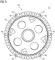
- the Figure 5 shows a variation of the arrangement and number of screw elements 52.
- Four screw elements are provided and these are arranged on the one hand in the lower circumference and on the other hand in the upper circumference symmetrically to a vertical central axis.
- a wrench surface 54 is arranged on the outer circumference of the ring gear bandage 20 in a circumferential area at 9 o'clock and 15 o'clock.
- a pliers-like tool can be attached to this, which can be used to compensate for the deformation caused by the dead weight.
Landscapes
- Engineering & Computer Science (AREA)
- General Engineering & Computer Science (AREA)
- Mechanical Engineering (AREA)
- Life Sciences & Earth Sciences (AREA)
- Sustainable Development (AREA)
- Sustainable Energy (AREA)
- Chemical & Material Sciences (AREA)
- Combustion & Propulsion (AREA)
- Retarders (AREA)
Priority Applications (1)
| Application Number | Priority Date | Filing Date | Title |
|---|---|---|---|
| EP23197215.9A EP4524432A1 (fr) | 2023-09-13 | 2023-09-13 | Bandage de roue creuse pour engrenage planétaire |
Applications Claiming Priority (1)
| Application Number | Priority Date | Filing Date | Title |
|---|---|---|---|
| EP23197215.9A EP4524432A1 (fr) | 2023-09-13 | 2023-09-13 | Bandage de roue creuse pour engrenage planétaire |
Publications (1)
| Publication Number | Publication Date |
|---|---|
| EP4524432A1 true EP4524432A1 (fr) | 2025-03-19 |
Family
ID=88021047
Family Applications (1)
| Application Number | Title | Priority Date | Filing Date |
|---|---|---|---|
| EP23197215.9A Withdrawn EP4524432A1 (fr) | 2023-09-13 | 2023-09-13 | Bandage de roue creuse pour engrenage planétaire |
Country Status (1)
| Country | Link |
|---|---|
| EP (1) | EP4524432A1 (fr) |
Citations (4)
| Publication number | Priority date | Publication date | Assignee | Title |
|---|---|---|---|---|
| WO2011047448A1 (fr) * | 2009-10-19 | 2011-04-28 | Hansen Transmisions International, Naamloze Vennootschap | Unité de train épicycloïdal pour une boîte de vitesses d'éolienne et porte-satellites destiné à être utilisé dans une telle unité de train épicycloïdal |
| CN202579964U (zh) * | 2012-05-03 | 2012-12-05 | 南京高速齿轮制造有限公司 | 风力发电机增速齿轮箱 |
| DE102014202459A1 (de) * | 2014-02-11 | 2015-08-13 | Siemens Aktiengesellschaft | Verbindungselement zum Verbinden einer Lagereinrichtung eines mit einer Rotornabe einer Windturbine zu verbindenden Rotorblatts mit einem Montageflansch der Rotornabe |
| EP3450775A1 (fr) * | 2017-08-28 | 2019-03-06 | 3M Innovative Properties Company | Élément de connexion augmentant la friction de connexion des composants, procédé de fixation d'un élément de connexion et utilisation d'un élément de connexion |
-
2023
- 2023-09-13 EP EP23197215.9A patent/EP4524432A1/fr not_active Withdrawn
Patent Citations (4)
| Publication number | Priority date | Publication date | Assignee | Title |
|---|---|---|---|---|
| WO2011047448A1 (fr) * | 2009-10-19 | 2011-04-28 | Hansen Transmisions International, Naamloze Vennootschap | Unité de train épicycloïdal pour une boîte de vitesses d'éolienne et porte-satellites destiné à être utilisé dans une telle unité de train épicycloïdal |
| CN202579964U (zh) * | 2012-05-03 | 2012-12-05 | 南京高速齿轮制造有限公司 | 风力发电机增速齿轮箱 |
| DE102014202459A1 (de) * | 2014-02-11 | 2015-08-13 | Siemens Aktiengesellschaft | Verbindungselement zum Verbinden einer Lagereinrichtung eines mit einer Rotornabe einer Windturbine zu verbindenden Rotorblatts mit einem Montageflansch der Rotornabe |
| EP3450775A1 (fr) * | 2017-08-28 | 2019-03-06 | 3M Innovative Properties Company | Élément de connexion augmentant la friction de connexion des composants, procédé de fixation d'un élément de connexion et utilisation d'un élément de connexion |
Similar Documents
| Publication | Publication Date | Title |
|---|---|---|
| DE3850415T2 (de) | Ausgeglichener frei-planetenantriebsmechanismus. | |
| EP2126354B1 (fr) | Éolienne et engrenage destiné à celle-ci | |
| EP1423606A1 (fr) | Lubrification pour dispositif de reglage d'angle d'attaque sur une pale de rotor d'eolienne | |
| EP1381793A2 (fr) | Transmission, en particulier transmission planetaire | |
| DE102016219008A1 (de) | Planetengetriebe mit Anlaufscheiben | |
| EP3550140B1 (fr) | Support de machine pour éolienne | |
| WO2016008737A1 (fr) | Montage des porte-satellites sur paliers lisses | |
| EP3323718A1 (fr) | Entraînement du rotor d'hélicoptère | |
| DE102015119173A1 (de) | Planetengetriebe sowie Verfahren zur Wartung eines Planetengetriebes | |
| DE102016219002A1 (de) | Planetengetriebe mit Anlaufscheiben | |
| EP3589839A1 (fr) | Unité de réglage pour régler l'azimut et/ou le pas d'une éolienne et procédé | |
| DE102016122205A1 (de) | Getriebe für eine Windenergieanlage | |
| EP4524432A1 (fr) | Bandage de roue creuse pour engrenage planétaire | |
| DE102020207991A1 (de) | Elektrischer Antrieb | |
| WO2024223554A1 (fr) | Engrenage planétaire avec liaison arbre-moyeu | |
| DE102021209955B4 (de) | Getriebe für ein Flurförderfahrzeug sowie Flurförderfahrzeug mit dem Getriebe | |
| DE102014206109A1 (de) | Drehteile eines Planetengetriebes | |
| EP4031783B1 (fr) | Série de boîtes de vitesses à trains planétaires, éolienne, application industrielle et utilisation de roulements | |
| WO2012034727A1 (fr) | Unité d'entraînement comprenant au moins un entraînement et au moins un différentiel planétaire | |
| EP4638951B1 (fr) | Engrenages planétaires ainsi que chaîne cinématique et éolienne avec un engrenage planétaire correspondant | |
| DE102015220159A1 (de) | Rotorwellenlagerung für eine Windkraftanlage | |
| EP4653716A1 (fr) | Liaison arbre-moyeu avec blocage axial | |
| EP3179138B1 (fr) | Dispositif et procédé de liaison de deux parties rotatives de machine | |
| EP4530495A1 (fr) | Élément de support pour composants de boîte de vitesses | |
| DE102010008198A1 (de) | Großlager für ein Planetengetriebe sowie Planetengetriebe mit dem Großlager |
Legal Events
| Date | Code | Title | Description |
|---|---|---|---|
| PUAI | Public reference made under article 153(3) epc to a published international application that has entered the european phase |
Free format text: ORIGINAL CODE: 0009012 |
|
| STAA | Information on the status of an ep patent application or granted ep patent |
Free format text: STATUS: THE APPLICATION HAS BEEN PUBLISHED |
|
| AK | Designated contracting states |
Kind code of ref document: A1 Designated state(s): AL AT BE BG CH CY CZ DE DK EE ES FI FR GB GR HR HU IE IS IT LI LT LU LV MC ME MK MT NL NO PL PT RO RS SE SI SK SM TR |
|
| STAA | Information on the status of an ep patent application or granted ep patent |
Free format text: STATUS: THE APPLICATION IS DEEMED TO BE WITHDRAWN |
|
| 18D | Application deemed to be withdrawn |
Effective date: 20250920 |