EP4524520A2 - Dosierdruckregelventil - Google Patents
Dosierdruckregelventil Download PDFInfo
- Publication number
- EP4524520A2 EP4524520A2 EP25155346.7A EP25155346A EP4524520A2 EP 4524520 A2 EP4524520 A2 EP 4524520A2 EP 25155346 A EP25155346 A EP 25155346A EP 4524520 A2 EP4524520 A2 EP 4524520A2
- Authority
- EP
- European Patent Office
- Prior art keywords
- pressure
- prv
- valve
- fluid
- restricting element
- Prior art date
- Legal status (The legal status is an assumption and is not a legal conclusion. Google has not performed a legal analysis and makes no representation as to the accuracy of the status listed.)
- Pending
Links
Images



Classifications
-
- F—MECHANICAL ENGINEERING; LIGHTING; HEATING; WEAPONS; BLASTING
- F16—ENGINEERING ELEMENTS AND UNITS; GENERAL MEASURES FOR PRODUCING AND MAINTAINING EFFECTIVE FUNCTIONING OF MACHINES OR INSTALLATIONS; THERMAL INSULATION IN GENERAL
- F16K—VALVES; TAPS; COCKS; ACTUATING-FLOATS; DEVICES FOR VENTING OR AERATING
- F16K37/00—Special means in or on valves or other cut-off apparatus for indicating or recording operation thereof, or for enabling an alarm to be given
- F16K37/0025—Electrical or magnetic means
- F16K37/005—Electrical or magnetic means for measuring fluid parameters
-
- G—PHYSICS
- G01—MEASURING; TESTING
- G01F—MEASURING VOLUME, VOLUME FLOW, MASS FLOW OR LIQUID LEVEL; METERING BY VOLUME
- G01F1/00—Measuring the volume flow or mass flow of fluid or fluent solid material wherein the fluid passes through a meter in a continuous flow
- G01F1/05—Measuring the volume flow or mass flow of fluid or fluent solid material wherein the fluid passes through a meter in a continuous flow by using mechanical effects
- G01F1/34—Measuring the volume flow or mass flow of fluid or fluent solid material wherein the fluid passes through a meter in a continuous flow by using mechanical effects by measuring pressure or differential pressure
- G01F1/36—Measuring the volume flow or mass flow of fluid or fluent solid material wherein the fluid passes through a meter in a continuous flow by using mechanical effects by measuring pressure or differential pressure the pressure or differential pressure being created by the use of flow constriction
- G01F1/363—Measuring the volume flow or mass flow of fluid or fluent solid material wherein the fluid passes through a meter in a continuous flow by using mechanical effects by measuring pressure or differential pressure the pressure or differential pressure being created by the use of flow constriction with electrical or electro-mechanical indication
-
- G—PHYSICS
- G01—MEASURING; TESTING
- G01F—MEASURING VOLUME, VOLUME FLOW, MASS FLOW OR LIQUID LEVEL; METERING BY VOLUME
- G01F15/00—Details of, or accessories for, apparatus of groups G01F1/00 - G01F13/00 insofar as such details or appliances are not adapted to particular types of such apparatus
- G01F15/005—Valves
-
- G—PHYSICS
- G05—CONTROLLING; REGULATING
- G05D—SYSTEMS FOR CONTROLLING OR REGULATING NON-ELECTRIC VARIABLES
- G05D16/00—Control of fluid pressure
- G05D16/028—Controlling a pressure difference
-
- G—PHYSICS
- G05—CONTROLLING; REGULATING
- G05D—SYSTEMS FOR CONTROLLING OR REGULATING NON-ELECTRIC VARIABLES
- G05D16/00—Control of fluid pressure
- G05D16/04—Control of fluid pressure without auxiliary power
- G05D16/06—Control of fluid pressure without auxiliary power the sensing element being a flexible membrane, yielding to pressure, e.g. diaphragm, bellows, capsule
- G05D16/063—Control of fluid pressure without auxiliary power the sensing element being a flexible membrane, yielding to pressure, e.g. diaphragm, bellows, capsule the sensing element being a membrane
- G05D16/0644—Control of fluid pressure without auxiliary power the sensing element being a flexible membrane, yielding to pressure, e.g. diaphragm, bellows, capsule the sensing element being a membrane the membrane acting directly on the obturator
- G05D16/0647—Control of fluid pressure without auxiliary power the sensing element being a flexible membrane, yielding to pressure, e.g. diaphragm, bellows, capsule the sensing element being a membrane the membrane acting directly on the obturator using one membrane without spring
-
- G—PHYSICS
- G05—CONTROLLING; REGULATING
- G05D—SYSTEMS FOR CONTROLLING OR REGULATING NON-ELECTRIC VARIABLES
- G05D16/00—Control of fluid pressure
- G05D16/04—Control of fluid pressure without auxiliary power
- G05D16/10—Control of fluid pressure without auxiliary power the sensing element being a piston or plunger
-
- G—PHYSICS
- G05—CONTROLLING; REGULATING
- G05D—SYSTEMS FOR CONTROLLING OR REGULATING NON-ELECTRIC VARIABLES
- G05D16/00—Control of fluid pressure
- G05D16/20—Control of fluid pressure characterised by the use of electric means
- G05D16/2086—Control of fluid pressure characterised by the use of electric means without direct action of electric energy on the controlling means
Definitions
- Pressure regulating devices are frequently used in industrial and residential systems designed to deliver fluid flows to one or more gaseous or liquid fluid loads.
- the pressure regulating devices may be employed to deliver or maintain the delivered fluid within predetermined pressure parameters selected based on, for example, system integrity, process controls, various equipment restrictions, and/or other reasons.
- Pressure regulating devices may operate by sensing pressure fluctuations and making corrective adjustments around a pressure setpoint. Such pressure regulating devices may be employed within fluid delivery systems to maintain pressures downstream of the device.
- pressure regulating valves may be used between a pumping station and a piping network serving consumers, in order to maintain a substantially constant water pressure in the piping network as demand among consumers fluctuates.
- pressure regulating valves may be used to reduce gas pressure from transmission pipelines to a distribution tap serving farm for a community.
- pressure regulating valves may be used between multiple primary and secondary branch circuits in order to control various processes involving the precise control of one or more fluids, or to provide relatively steady-state pressures to, for example, air or water service branches which experience unpredictable, transitory demands. Because many end-user fluid demands require the fluid to be delivered to a secondary branch or maintained in a main branch in accordance with predetermined pressure parameters, pressure regulating valves are often employed to substantially maintain downstream pressures.
- the PRV may be configured to receive a higher pressure fluid at an inlet of the PRV, cause a pressure drop of the fluid using a restricting element (e.g., a valve disc), and provide a reduced pressure fluid to a fluid circuit in fluid communication with the pressure regulating valve outlet.
- the pressure drop caused by the PRV is dependent on a position of the restricting element within the PRV.
- the PRV senses the pressure and adjusts the position of the restricting element in order to increase or decrease the pressure drop caused as the fluid flows through the valve.
- the PRV may include an inlet pressure sensor configured to generate and provide an inlet pressure signal indicative of the pressure at the inlet of the PRV to the control circuitry, and may include an outlet pressure sensor configured to generate and provide an outlet pressure signal indicative of the pressure at the out of the PRV to the control circuitry, and the control circuitry can be configured to determine the differential pressure based on the inlet pressure signal and the outlet pressure signal.
- the PRV includes a valve position sensor (VPS) configured to generate and provide a valve position signal indicative of a position of the restricting element to the control circuitry.
- the control circuitry is configured to determine a flow rate through the PRV using the differential pressure and the valve position signal.
- the PRV is configured to communicate with one or more user devices, such as a mobile phone, smartphone, tablet computer, personal computer, desktop computer, personal digital assistant, and the like.
- the PRV may communicate with the user device via a wired or wireless connection to the user device.
- the control circuitry of the PRV may exchange data with the user device, such as metering information (e.g., a consumption of fluid by a fluid system over a time interval), estimated costs of the metered flow, historical metering information (e.g., metered flow per day over a given week, etc.), error codes, and/or other operating parameters of the fluid system.
- the user device includes control circuitry configured to control one or more parameters of the PRV.
- the control circuitry of the PRV can provide fluid usage information for a user-selected time interval (e.g., a particular time of day, a particular day, days, one or more weeks, or one or more months) or other information regarding a user selected requested history of metered flow.
- the control circuitry of the PRV provides metering information to an external computing system configured to monitor various operating parameters of a fluid system serving multiple fluid loads which actuate intermittently and independently.
- the external computing system may be configured to estimate an individual flow rate consumed by each individual fluid load based on an overall flowrate into the fluid system, and the PRV may provide metering information to the external computing system in order to, for example, increase an accuracy of the individual estimates.
- the PRV may translate the restricting element to alter the spatial and/or obstruction characteristics of the flow area, which may alter the pressure loss experienced by the fluid as it travels through the PRV. Control of this pressure drop through the PRV allows control of a downstream pressure when the PRV bridges a higher pressure main circuit and a lower pressure branch circuit.
- the restricting element generating the fluid pressure loss may be, for example, a poppet valve, a needle valve, a gate valve, a globe valve, spool valve, or some other mechanism or combination of mechanisms.
- the restricting element may be a double-ported valve.
- the PRV is configured to position the restricting element using a sensing element within the body of the PRV.
- the sensing element is configured to sense the pressure at the PRV outlet and move (e.g., translate or flex) as the PRV outlet pressure varies.
- the sensing element may be operatively connected to the body of the PRV.
- the sensing element may be a diaphragm or piston in fluid communication with a flow section at the PRV outlet, with the diaphragm or piston configured such that an increase in pressure at the PRV outlet causes movement (e.g., translation or flexing) in a first direction, and a decrease in pressure at the PRV outlet causes movement (e.g., translation or flexing) in a second direction substantially opposite the first direction.
- Movement of the sensing element in the first direction causes movement of the restricting element in a closing direction within the PRV, such that the pressure drop through the PRV increases and the PRV outlet pressure decreases.
- Movement of the sensing element in the second direction causes movement of the restricting element in an opening direction within the PRV, such that the pressure drop through the PRV decreases and the PRV outlet pressure increases.
- the PRV is configured to sense pressure at the PRV outlet and adjust the position of the restricting element in response to changes in the PRV outlet pressure, in order to maintain a pressure in the fluid circuit supplied by the PRV.
- the PRV is further configured to provide a reference force to the sensing element, such that the amount of sensing element movement generated during operation of the PRV is dependent on both the pressure at the PRV outlet and the reference force applied by the PRV to the sensing element.
- the magnitude of the reference force is substantially independent of a pressure of the fluid flowing through the PRV, such as at the PRV outlet pressure and the PRV inlet pressure.
- the magnitude of the reference force is dependent on a position and/or configuration of the sensing element.
- the reference force may be applied via a reference force element, such as, but not limited to, a spring or a gas dome acting on the sensing element, with movement of the sensing element tending to compress or expand the spring or the gas in the gas dome.
- the compression or expansion of the reference force element based on the position and/or configuration of the sensing element thus acts to alter the reference force based on movement of the sensing element. Because movement of the sensing element also modifies the position of the restricting element with the PRV, the PRV is thus configured such that the position of the restricting element modifies the magnitude of the reference force.
- the reference force may be adjustable (e.g., by adjusting a baseline displacement of the spring, or a pressure of a gas in the gas dome) to allow for adjustment of the set point pressure.
- the PRV can be configured such that the reference force can be adjusted manually by a user or automatically by control circuitry.
- the PRV is a normally open valve employed to substantially maintain a downstream pressure.
- the PRV may be configured to operate toward or into a closed position (e.g., by at least decreasing the volume of the flow area) as the downstream pressure increases, and operate toward or into an open position (e.g., by at least increasing the volume of the flow area) as the downstream pressure decreases.
- the PRV may be configured to respond to downstream pressure. Decreasing downstream pressures may be indicative of an increase in demand, prompting the PRV to operate toward or into an open position to allow more flow to a downstream branch circuit.
- increasing downstream pressures may be indicative of a decrease in demand, prompting the PRV to operate toward or into a closed position to provide less flow to the downstream branch circuit.
- the PRV may substantially match the fluid supply from a main circuit to the fluid demand generated in the branch circuit, while substantially maintaining a set pressure downstream of the PRV.
- downstream means the direction of a fluid flowing from a higher pressure area to a lower pressure area.
- Upstream denotes a direction opposite the downstream direction.
- an "opening direction” denotes movement of a restricting element and/or a sensing element in a direction which alters the flow area to decrease the pressure loss experienced by a fluid traveling through the PRV.
- a “closing direction” denotes movement of a restricting element and/or sensing element in a direction which alters the flow area to increase the pressure loss experienced by a fluid traveling through the PRV.
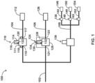
- FIG. 1 illustrates an example fluid system 100 including a main circuit 102 configured to provide a fluid (gas or liquid) to branch circuits 104, 106, and 108.
- Branch circuit 104 is configured to be supplied with a fluid from main circuit 102 via PRV 110, and configured to provide the fluid to fluid load 112.
- PRV 110 is configured to receive higher pressure fluid from, for example, main circuit 102, and supply the fluid at a lower pressure to branch circuit 104.
- PRV 110 includes valve body 111 configured to define a flow path from main circuit 102 to branch circuit 104, and includes a restricting element (not shown in FIG. 1 ) configured to alter a pressure of the fluid as it flow through the flow path defined by PRV 110.
- Branch circuit 104 is configured to provide the lower pressure fluid to fluid load 112.
- Fluid load 112 may be a load intended to receive fluid at some secondary pressure below the supply pressure of the fluid provided by main circuit 102.
- fluid load 112 might be a water or air connection intended to operate under relatively constant or transitory demand, where equipment and/or other considerations require that the air or water be provided at a lower pressure than that present within main circuit 102.
- Fluid load 112 might be, for example, a primary residential water connection, a water supply to a specific household appliance such as a water heater, a dishwasher, or a washing machine, a service air connection for the operation of air-driven tools, a pneumatic supply to some pneumatically operated system, a cooling water supply to specific equipment, or some other load intended to operate at pressures lower than that supplied by main circuit 102.
- PRV 110 is configured to operate in accordance with a specific pressure setpoint, in order to maintain a substantially constant secondary pressure in branch circuit 104 as the main supply pressure of main circuit 102 varies and/or the fluid demand from fluid load 112 varies.
- PRV 110 may be configured to maintain a secondary pressure in branch circuit 104 within 1% to about 30% of a setpoint pressure, such as within 30% of the pressure setpoint, within 20% of the pressure setpoint, within 10% of the setpoint pressure, within 5% of the setpoint pressure, or within 1% of the setpoint pressure.
- PRV 110 includes a reference force element configured to impart a reference force (e.g., a pressure and/or force) to a sensing element (not shown in FIG. 1 ) within PRV 110.
- the reference force element may be included in a spring loaded, gas loaded, or gas and spring loaded dome, such as dome 114 in the example of FIG. 1 .
- the sensing element may be configured such that some portion of the fluid flow proceeding through PRV 110 imparts a pressure generally counter-acting the pressure and/or force imparted by the reference force element of dome 114.
- the sensing element is configured to translate in response to changes in the reference force of the reference force element, changes in the counter-acting pressure of the fluid flow through PRV 110, or changes to both.
- Dome 114 may be configured such that the pressure and/or force imparted by the reference force element is adjustable, e.g., manually by a user or automatically by control circuitry of PRV 110 or another device. Adjustments to the reference force element may thus be utilized as a control for the pressure setpoint of branch circuit 104.
- PRV 110 includes control circuitry 116 configured to determine a differential pressure over a section of the flow path defined by PRV 110.
- the differential pressure may be a pressure difference between an inlet pressure at a flow location upstream of the restricting element (either within PRV 110 or within main circuit 102) and an outlet pressure at a second flow location downstream of the restricting element (either within PRV 110 or within branch circuit 104).
- the inlet pressure is indicative of a pressure at an inlet 115 of PRV 110 and the outlet pressure is indicative of a pressure at an outlet 117 of PRV 110.
- Control circuitry 116 may be configured to receive, from one or more sensors, a signal indicative of the inlet pressure and a signal indicative of the outlet pressure and determine the differential pressure using the indicative inlet pressure and the indicative outlet pressure signals. In some examples, control circuitry 116 is configured to receive a differential pressure signal reflecting the differential pressure between the inlet pressure and the outlet pressure.
- Control circuitry 116 is further configured to determine a position of the restricting element within PRV 110.
- the position of the restricting element is indicative of the spatial and/or obstruction characteristics of the flow area within PRV 110 when the restricting element is in a given position.
- Control circuitry 116 can determine the position of the restricting element using any suitable technique, such as one or more of: based on sensing of an actual location of the restricting element, an integration of sensed movement of the restricting element, a position of a valve actuator and/or valve component coupled to the restricting element, or other suitable techniques.
- Control circuitry 116 is configured to determine a position of the restricting element over a range of PRV 110 positions between (and may include) PRV 110 fully shut and PRV 110 fully open.
- Control circuitry 116 may be configured to determine a position of the restricting element as a value within continuous data (e.g., any value within the range) or as a value within discrete data (e.g., one of a finite number of discrete values).
- Control circuitry 116 is configured to determine a flow rate through PRV 110 using the differential pressure and the position of the restricting element. In some examples, control circuitry 116 is configured to determine the flow rate by at least evaluating an expression (e.g., a function) wherein a flowrate Q is proportional to the position of the restricting element and one or more of the differential pressure, the inlet pressure, or the outlet pressure.
- an expression e.g., a function
- Control circuitry 116 may be located adjacent or within a housing of PRV 110, or be positioned elsewhere within system 100. Further, although control circuitry of individual PRVs of system 100 are described herein and illustrated at FIG. 1 , in some examples, one controller (including control circuitry) can determine an individual flow rate through an individual PRV for multiple PRVs. That is, system 100 can include one or more controllers configured to determine the flow rate through the PRV described herein. In some examples, control circuitry 116 is configured to periodically determine the flow rate and integrate the flow rate over a period time in order to determine a volumetric amount of fluid which has passed through the PRV over the period of time (e.g., to meter the fluid flow through PRV 110).
- PRV 110 is configured to sense the differential pressure.
- PRV 110 may include an inlet pressure sensor 118 configured to provide an indication of a pressure upstream of the restricting element, such as an inlet pressure at the inlet of PRV 110 or elsewhere within main circuit 102.
- PRV 110 may include an outlet pressure sensor 120 configured to provide an indication of a pressure downstream of the restricting element, such as an outlet pressure at the outlet of PRV 110 or elsewhere within branch circuit 104.
- Inlet pressure sensor 118 and/or outlet pressure sensor 120 may be located adjacent or within a housing of PRV 110, or be positioned elsewhere within system 100.
- Inlet pressure sensor 118 and outlet pressure sensor 120 can include any suitable pressure sensing circuitry and other structure configured to generate a signal indicative of the pressure at the sensing location.
- inlet pressure sensor 118 and outlet pressure sensor 120 are components within a differential pressure sensor, and the differential pressure sensor includes suitable pressure sensing circuitry and other structure configured to generate a signal indicative of a difference in a pressure sensed by inlet pressure sensor 118 and a pressure sensed by outlet pressure sensor 120.
- Control circuitry 116 may be configured to periodically determine the flow rate and integrate the flow rate over a period time in order to determine a volumetric amount of fluid which has passed through the PRV over the period of time (e.g., to meter the fluid flow through PRV 110).
- Control circuitry 232 can determine the inlet pressure and the outlet pressure of PRV 200 using any suitable technique.
- control circuitry 232 is configured to receive an inlet pressure signal generated by a first sensor and indicative of the inlet pressure and an outlet pressure signal generated by a second sensor and indicative of the outlet pressure and determine the differential pressure using the inlet pressure signal and the outlet pressure signals.
- control circuitry 232 is configured to receive the inlet pressure signal from inlet pressure sensor 240 via communication link 234 and receive the outlet pressure signal from outlet pressure sensor 242 via communication link 236.
- control circuitry 232 is configured to determine the differential pressure using one or more pressure sensors.
- PRV 200 includes an inlet pressure sensor 240 configured to generate a signal indicative of a pressure within high pressure side 215 of PRV 200, and an outlet pressure sensor 242 configured to generate a signal indicative of a pressure within low pressure side 217 of PRV 200.
- Inlet pressure sensor 240 and/or outlet pressure sensor 242 may be located adjacent to or within some enclosure defined by valve body 201, or may be within a sensor housing configured to remain substantially separate from valve body 201.
- inlet pressure sensor 240 and outlet pressure sensor 242 are components within a differential pressure sensor configured to provide a signal indicative of a difference in a pressure sensed by inlet pressure sensor 240 and a pressure sensed by outlet pressure sensor 242.
- PRV 251 includes valve body 201, PRV inlet 202, PRV outlet 204, restricting element 206, flow area 210, high pressure side 215, low pressure side 217, control circuitry 232, communication link 234, communication link 236, inlet pressure sensor 240, outlet pressure sensor 242, and valve bonnet 248.
- PRV 251 further includes sensing element 252, reference force element 254, and reference force adjuster 256.
- Sensing element 252 is an example of sensing element 218 ( FIG. 2 )
- reference force element 254 is an example of reference for element 224
- reference force adjuster 256 is an example of reference force adjuster 228.
- PRV 251 is similar to PRV 200 of FIG. 2 but includes a different reference force element 254.
- PRV 251 is configured such that a fluid pressure within low pressure side 217 of PRV 251 acts to exert a force (e.g., F1) on sensing element 252 (e.g., on second side 264 of diaphragm 258) which tends to cause movement of restricting element 206 in a closing direction, while reference force element 254 (e.g., dome 268) causes a force (e.g., F2) on sensing element 252 tending to cause movement of restricting element 206 in an opening direction.
- Diaphragm 258 may be configured to bend or flex in response to force F1 and/or force F2, such that the bending or flexing causes movement of restricting element 206.
- diaphragm 258 may define perimeter 259 surrounding diaphragm 258, with perimeter 259 mechanically coupled and/or fixably attached to valve body 201 around all or some part of perimeter 226.
- motion of sensing element 252 e.g., diaphragm 258 causes motion of restricting element 206 and adjustment of flow area 210.
- Adjusting flow area 210 adjusts a pressure drop of fluid flow through flow area 210.
- Dome 268 may be configured such that a gas in dome chamber 270 is in fluid communication with second side 264 of diaphragm 258. Dome 268 may be configured such that the gas in dome chamber 270 is in fluid communication with second area 266 and exerts a gas pressure on second area 266. Diaphragm 258 may be configured such that the exertion of the gas pressure on second area 266 causes the reference force (e.g., F2) to act on the second side 264 of diaphragm 258.
- F2 reference force
- dome 268 is configured to cause the gas in dome chamber 270 to exert a pressure a portion of dome 268 coupled to diaphragm 258 (e.g., a dome plate (not shown)), and dome 268 is configured to transmit the reference force caused by the gas in dome chamber 270 to the second side 264 of diaphragm 258.
- diaphragm 258 e.g., a dome plate (not shown)
- reference force adjuster 256 can be manually adjusted by a user (e.g., using a compressor or a source of pressurized gas), and/or may be automatically adjusted by control circuity 232 (e.g., using a compressor or a source of pressurized gas).
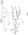
- Secondary branch 288 may be a water supply to a plumbing system 290 supplying one or more fluid loads, such as fluid load 291, fluid load 292, fluid load 293, and fluid load 294. Secondary branch 288 may be, for example, a residential water main and plumbing system 290 may be a residential plumbing system.
- PRV 280 is configured to determine a quantity of flow (e.g., a volume) consumed by plumbing system 290 (e.g., by fluid loads 291, 292, 293, 294) over a time interval (e.g., seconds, minutes, hours, days, etc.).
- Fluid loads 291, 292, 293, 294 may be residential water loads such as a shower, bath, kitchen and/or bathroom faucet, dishwasher, washing machine, toilet, automatically refilling water tank, and the like. Fluid loads 291, 292, 293, 294 may be fluid loads which intermittently actuate (or are actuated), and may demand different flow rates depending on an operating condition of the fluid load (e.g., a particular type of dishwasher cycle, a degree to which a faucet is opened, etc.). Fluid loads 291, 292, 293, 294 may be hydraulically connected in series, in parallel, or in a combination of series and parallel. For example, within plumbing system 290, fluid load 291 and fluid load 292 are hydraulically connected in series to plumbing branch 296 while fluid load 293 and fluid load 294 are hydraulically connected in parallel to plumbing branch 298 (via branch 299 and branch 301 respectively).
- PRV 280 includes a communication device (not illustrated in FIG. 4 ) configured to enable PRV 280 to communicate via a wired or wireless connection 300 to one or more user devices 302.
- the communication device may include a Bluetooth transmitter and receiver, a Wi-Fi transmitter and receiver, a Zigbee transceiver, a near-field communication transceiver, or other circuitry configured to allow PRV 280 to communicate with user device 302.
- the communication device may allow PRV 280 to exchange data with user device 302.
- exchanged data examples include metering information (e.g., consumption of fluid by plumbing system 290 over a time interval), estimated costs of the metered flow, historical metering information (e.g., metered flow per day over a given week, etc.), error codes, and/or other operating parameters or system performance characteristics for plumbing system 290.
- user device 302 may be configured to execute an application for controlling one or more parameters of PRV 280.
- control circuitry of PRV 280 is configured to receive information indicative of a user selection of a desired time interval, a desired history of metered flow, and other user inputs, and the control circuitry may provide information to user device 302 based on the information indicative of the user selection.
- User device 302 may be, include, or otherwise be used in combination with a mobile phone, smartphone, tablet computer, personal computer, desktop computer, personal digital assistant, router, modem, remote server or cloud computing device, and/or related device allowing PRV 280 to communicate over a communication network such as, for example, the Internet or other wired or wireless connection. Communicating via the wired or wireless connection 300 may allow PRV 280 to be configured, controlled, or otherwise exchange data with user device 302. In some examples, PRV 280 communicating via wired or wireless connection 300 may allow a user to set up PRV 280 when first installing PRV 280 in plumbing system 290. In some examples, PRV 280 and user device 302 communicate through a wireless network device such as a router or a switch.
- a wireless network device such as a router or a switch.
- PRV 280 and user device 302 communicate through a wired connection such as an ethernet port, USB connection, or other wired communication network.
- a user can interact with PRV 280 via a user interface of a mobile phone, a tablet, a computer, or other device.
- user device may communicate with PRV 280 via network 304.
- PRV 280 may, via the communication device, communicate via wired or wireless connection 300 with an external computing system 306.
- External computing system 306 may be, for example, a database configured to record information from PRV 280, processing circuitry configured to receive and conduct analysis om information received from PRV 280, and the like.
- wired or wireless connection 300 enables PRV 280 to communicate with external computing system 306 via a wireless connection which includes a network device such as a router, ethernet port, or switch.
- PRV 280 and external computing system 306 may also communicate through a wired connection such as an ethernet port, USB connection, or other wired communication network.
- Communicating via the wired or wireless connection 300 may allow PRV 280 (e.g., control circuitry of PRV 280) to exchange data with external computing system 306, such that external computing system 306 may be located remotely from PRV 280 and plumbing system 290.
- external computing system 306 may be, include, or otherwise be used in combination with a remote server, cloud computing device, or network of controllers configured to communicate with each other.
- PRV 280 may provide metering information to external computing system 306 in order to assist external computing system 306 in the monitoring of various operating parameters associated with plumbing system 290.
- plumbing system 290 may include a communications enabled flow measurement device 308 configured to provide time-stamped volume-rate measurements of the fluid (e.g., water) entering plumbing system 290 via secondary branch 288, such as the BUOY Whole Home Water Controller available from Resideo Technologies.
- Flow measurement device 308 may be configured to provide the time-stamped volume-rate measurements to external computing system 306 via wired or wireless connection 310.
- External computing system 306 may be configured to analyze the time-stamped volume-rate measurements as a time-series of data in order to estimate which of fluid loads 291, 292, 293, and/or 294 were actuated at various points in the time-series of data.
- PRV 280 may provide metering information to external computing system 306 in order to increase an accuracy of the estimate, decrease computing time required by external computing system 306, serve as an input to a learning algorithm executed by external computing system 306, or other reasons.
- PRV 280 may be configured to provide metering information to external computing system 306 on a schedule requested by external computing system 306 or on-demand from external computing system 306.
- PRV 280 may be configured to provide a time-series of data to external computing system 306 based on formatting requirements received from external computing system 306 (e.g., provide metering for every 0.1 seconds over a designated time frame, provide metering for each day over the last week, and the like).
- FIG. 5 illustrates a flow diagram of an example technique for determining a flow rate.
- the technique is mainly described with reference to PRV 200 ( FIG. 2 ), PRV 251 ( FIG. 3 ), and/or PRV 280 ( FIG. 4 ), in other examples, the technique may be used with PRV 110, PRV 124, PRV 136, PRV 138, PRV 140, and/or PRV 142 of FIG. 1 or another PRV.
- control circuitry 116, 130, 232 alone or in combination with control circuitry of other devices can perform any part of the technique shown in FIG. 5
- control circuitry 232 determines a differential pressure over a section of a flow path defined by a valve body 201 of PRV 200, 251, 280 (502).
- the flow path may be defined between PRV inlet 202 and PRV outlet 204 of PRV 200, 251, 280.
- valve body 201 may define the flow path from PRV inlet 202, through flow area 210 between valve disc 214 and valve seat 216, and to PRV outlet 204.
- control circuitry 232 determines the differential pressure (502) by at least determining a pressure difference between an inlet pressure at a flow location upstream of restricting element 206 and an outlet pressure at a second flow location downstream of restricting element 206.
- the inlet pressure is indicative of a pressure at PRV inlet 202 of PRV 200, 251 and the outlet pressure is indicative of a pressure at PRV outlet 204 of PRV 200, 251.
- control circuitry 232 may receive, from sensor 240 ( FIG. 2 ) an inlet pressure signal indicative of the inlet pressure, and receive from sensor 242 ( FIG. 2 ), an outlet pressure signal indicative of the outlet pressure, and determine the differential pressure using the inlet pressure and the outlet pressure signals.
- control circuitry 232 can receive a signal generated by a differential pressure sensor (e.g., differential pressure sensor 134 ( FIG. 1 ), the signal being indicative of the differential pressure, and determine the differential pressure (502) based on such a signal.
- a differential pressure sensor e.g., differential pressure sensor
- Control circuitry 232 determines a position of a restricting element 206 within the flow path defined valve body 201 of PRV 200, 251 (504). For example, control circuitry 232 can receive a signal indicative of the position of restricting element 206 generated by a valve position sensor (VPS) 244, 276 of PRV 200, 251. For example, the signal can be indicative of a position of valve stem 212, valve disc 214, sensing element 218, 252, extension stem 245, 277, and/or other components of PRV 200, 251 having a position which influences the position of restricting element 206.
- VPS valve position sensor
- Control circuitry 232 determines a flow rate based on the differential pressure and the position of restricting element 206 (506). For example, control circuitry 232 can determine the flow rate by at least evaluating an expression wherein the flowrate Q is proportional to the position of restricting element 206 and one or more of the differential pressure, the inlet pressure upstream of restricting element 206, and/or the outlet pressure down stream of restricting element 206. In some examples, control circuitry 232 selects an expression from among one or more expressions based on the values of the differential pressure, the inlet pressure upstream of restricting element 206, the outlet pressure downstream of restricting element 206, and/or the position of restricting element 206.
- control circuitry 232 determine the flow rate by at least using a look-up data set defining flow rates in an n-dimensional space having individual dimensions defined by the inlet pressure upstream of restricting element 206, the outlet pressure downstream of restricting element 206, the differential pressure, the position of restricting element 206, and/or combinations thereof.
- control circuitry 232 determines a flow volume over a time interval by at least integrating the flow rate over the interval. For example, control circuitry 232 can perform a numerical integration using discrete time intervals. Control circuitry 232 may provide an indication of the determined flow volume as an output, e.g., over a single discrete time interval (e.g., 0.1 seconds) or over multiple discrete time intervals (e.g., a total flow volume over a minute based on a series of flow rates determined at discrete time intervals less than a minute).
- a single discrete time interval e.g., 0.1 seconds
- multiple discrete time intervals e.g., a total flow volume over a minute based on a series of flow rates determined at discrete time intervals less than a minute.
- control circuitry 232 communicates the determined flow volume, the determined flow rate, and/or other information to user device 302 ( FIG. 4 ) using wired or wireless connection 300.
- User device 302 may also communicate information to control circuitry 232.
- the communicated information can include, for example, metering information, estimated costs of the metered flow, historical metering information, error codes, and/or other operating parameters or system performance characteristics of a fluid system (e.g., plumbing system 290) monitored by PRV 280.
- control circuitry 232 communicates with external computing system 306, e.g., to transmit metering information determined by PRV 280 to system 306.
- Processing circuitry of external computing system 306 may determine various operating parameters of a fluid system (e.g., plumbing system 290) using flow measurement device 308 and the information from PRV 280.
- the processing circuitry may use information (e.g., metering information) from PRV 280 as an input to a learning algorithm executed by external computing system 306.
- PRV 280 can provide the information to external computing system 306 on a schedule requested by external computing system 306 or on-demand from external computing system 306.
- control circuitry 116 FIG. 1
- control circuitry 232 FIG. 2
- other control circuitry processing circuitry, sensors, or various constituent components
- various aspects of the techniques may be implemented within one or more processors, including one or more microprocessors, DSPs, ASICs, FPGAs, or any other equivalent integrated or discrete logic circuitry, as well as any combinations of such components, embodied in any suitable device.
- Processing circuitry, control circuitry, and sensing circuitry, as well as other processors, controllers, and sensors described herein, may be implemented at least in part as, or include, one or more executable applications, application modules, libraries, classes, methods, objects, routines, subroutines, firmware, and/or embedded code, for example.
- analog circuits, components and circuit elements may be employed to construct one, some or all of the control circuitry and sensors, instead of or in addition to the partially or wholly digital hardware and/or software described herein. Accordingly, analog or digital hardware may be employed, or a combination of the two.
- the functions described in this disclosure may be implemented in hardware, software, firmware, or any combination thereof. If implemented in software, the functions may be stored on, as one or more instructions or code, a computer-readable medium and executed by a hardware-based processing unit.
- the computer-readable medium may be an article of manufacture including a non-transitory computer-readable storage medium encoded with instructions. Instructions embedded or encoded in an article of manufacture including a non-transitory computer-readable storage medium encoded, may cause one or more programmable processors, or other processors, to implement one or more of the techniques described herein, such as when instructions included or encoded in the non-transitory computer-readable storage medium are executed by the one or more processors.
- Example non-transitory computer-readable storage media may include RAM, ROM, programmable ROM (PROM), erasable programmable ROM (EPROM), electronically erasable programmable ROM (EEPROM), flash memory, a hard disk, a compact disc ROM (CD-ROM), a floppy disk, a cassette, magnetic media, optical media, or any other computer readable storage devices or tangible computer readable media.
- a computer-readable storage medium comprises non-transitory medium.
- the term "non-transitory” may indicate that the storage medium is not embodied in a carrier wave or a propagated signal.
- a non-transitory storage medium may store data that can, over time, change (e.g. , in RAM or cache).
- the present disclosure includes the following examples.
- Example 1 A valve comprising: a valve body defining a defining a flow path; a restricting element within the flow path; a sensing element configured to modify a position of the restricting element, wherein the sensing element defines a first area in fluid communication with the flow path and a second area fluidly isolated from the flow path; and control circuitry configured to: determine a differential pressure over a section of the flow path, determine the position of the restricting element, and determine a flow rate based on the differential pressure and the position of the restricting element.
- Example 2 The valve of example 1, further comprising: a valve inlet in fluid communication with the valve body; and a valve outlet in fluid communication with the valve body, wherein valve body defines the flow path from the valve inlet to the valve outlet, and wherein the restricting element is within the flow path between the valve inlet and the valve outlet.
Landscapes
- Physics & Mathematics (AREA)
- Engineering & Computer Science (AREA)
- Fluid Mechanics (AREA)
- General Physics & Mathematics (AREA)
- Automation & Control Theory (AREA)
- General Engineering & Computer Science (AREA)
- Mechanical Engineering (AREA)
- Control Of Fluid Pressure (AREA)
- Flow Control (AREA)
- Safety Valves (AREA)
Applications Claiming Priority (3)
| Application Number | Priority Date | Filing Date | Title |
|---|---|---|---|
| US16/878,349 US11608911B2 (en) | 2020-05-19 | 2020-05-19 | Metering pressure regulating valve |
| EP21723221.4A EP4154082A1 (de) | 2020-05-19 | 2021-04-30 | Dosierdruckregelventil |
| PCT/EP2021/061491 WO2021233662A1 (en) | 2020-05-19 | 2021-04-30 | Metering pressure regulating valve |
Related Parent Applications (1)
| Application Number | Title | Priority Date | Filing Date |
|---|---|---|---|
| EP21723221.4A Division EP4154082A1 (de) | 2020-05-19 | 2021-04-30 | Dosierdruckregelventil |
Publications (2)
| Publication Number | Publication Date |
|---|---|
| EP4524520A2 true EP4524520A2 (de) | 2025-03-19 |
| EP4524520A3 EP4524520A3 (de) | 2025-04-02 |
Family
ID=75787101
Family Applications (2)
| Application Number | Title | Priority Date | Filing Date |
|---|---|---|---|
| EP25155346.7A Pending EP4524520A3 (de) | 2020-05-19 | 2021-04-30 | Dosierdruckregelventil |
| EP21723221.4A Ceased EP4154082A1 (de) | 2020-05-19 | 2021-04-30 | Dosierdruckregelventil |
Family Applications After (1)
| Application Number | Title | Priority Date | Filing Date |
|---|---|---|---|
| EP21723221.4A Ceased EP4154082A1 (de) | 2020-05-19 | 2021-04-30 | Dosierdruckregelventil |
Country Status (5)
| Country | Link |
|---|---|
| US (1) | US11608911B2 (de) |
| EP (2) | EP4524520A3 (de) |
| KR (1) | KR20230011312A (de) |
| CN (1) | CN220651136U (de) |
| WO (1) | WO2021233662A1 (de) |
Families Citing this family (3)
| Publication number | Priority date | Publication date | Assignee | Title |
|---|---|---|---|---|
| US20220082178A1 (en) * | 2020-09-11 | 2022-03-17 | Patriot Research Center, LLC (DBA Atlas Pressure Control) | Sensing gate valve position |
| US20230105634A1 (en) * | 2021-10-05 | 2023-04-06 | Brown Hawk Technologies, LLC | Multiphase Flowmeter |
| WO2024231336A1 (en) * | 2023-05-08 | 2024-11-14 | Eltronic Fueltech A/S | A combustion engine, a fuel system for the combustion engine, and a method of supplying fuel to the combustion engine |
Family Cites Families (16)
| Publication number | Priority date | Publication date | Assignee | Title |
|---|---|---|---|---|
| US3633416A (en) | 1970-05-07 | 1972-01-11 | Columbia Gas Syst | Method and apparatus for controlling and metering gas flow |
| NL9401099A (nl) | 1994-06-30 | 1996-02-01 | Deltec Fuel Systems Bv | Gasdrukregelaar met geintegreerde debietmeting. |
| JPH11175166A (ja) | 1997-12-15 | 1999-07-02 | Tlv Co Ltd | 流量測定機能付き減圧弁 |
| JP3623125B2 (ja) | 1999-04-06 | 2005-02-23 | アドバンス電気工業株式会社 | 流量測定方法および流量測定装置 |
| US6895351B2 (en) | 1999-06-29 | 2005-05-17 | Fisher Controls International Llc | Regulator flow measurement apparatus |
| BRPI0807862B8 (pt) | 2007-01-24 | 2023-01-31 | I2O Water Ltd | Controlador e sistema de controle para uma válvula redutora de pressão |
| US8271210B2 (en) * | 2009-12-09 | 2012-09-18 | Pivotal Systems Corporation | Method and apparatus for enhancing in-situ gas flow measurement performance |
| US9995486B2 (en) * | 2011-12-15 | 2018-06-12 | Honeywell International Inc. | Gas valve with high/low gas pressure detection |
| US8833384B2 (en) * | 2012-08-06 | 2014-09-16 | Schneider Electric Buildings, Llc | Advanced valve actuation system with integral freeze protection |
| CN106662883B (zh) * | 2014-09-01 | 2020-11-10 | 日立金属株式会社 | 质量流量控制装置 |
| US9645584B2 (en) * | 2014-09-17 | 2017-05-09 | Honeywell International Inc. | Gas valve with electronic health monitoring |
| JP7245600B2 (ja) * | 2016-12-15 | 2023-03-24 | 株式会社堀場エステック | 流量制御装置、及び、流量制御装置用プログラム |
| USD866375S1 (en) | 2017-08-02 | 2019-11-12 | Buoy Labs, Inc. | Water flow monitoring device |
| US20200124759A1 (en) * | 2017-11-07 | 2020-04-23 | Takasago Electric, Inc. | Joint system |
| US11781895B2 (en) | 2018-02-23 | 2023-10-10 | Buoy Labs, Inc. | Fluid flow analysis and management |
| US20190173302A1 (en) | 2017-12-04 | 2019-06-06 | Keri Waters | Fluid flow detector with a detachable battery module |
-
2020
- 2020-05-19 US US16/878,349 patent/US11608911B2/en active Active
-
2021
- 2021-04-30 KR KR1020227040118A patent/KR20230011312A/ko active Pending
- 2021-04-30 EP EP25155346.7A patent/EP4524520A3/de active Pending
- 2021-04-30 CN CN202190000486.2U patent/CN220651136U/zh active Active
- 2021-04-30 WO PCT/EP2021/061491 patent/WO2021233662A1/en not_active Ceased
- 2021-04-30 EP EP21723221.4A patent/EP4154082A1/de not_active Ceased
Also Published As
| Publication number | Publication date |
|---|---|
| US11608911B2 (en) | 2023-03-21 |
| EP4524520A3 (de) | 2025-04-02 |
| US20210364100A1 (en) | 2021-11-25 |
| EP4154082A1 (de) | 2023-03-29 |
| CN220651136U (zh) | 2024-03-22 |
| WO2021233662A1 (en) | 2021-11-25 |
| KR20230011312A (ko) | 2023-01-20 |
Similar Documents
| Publication | Publication Date | Title |
|---|---|---|
| EP4524520A2 (de) | Dosierdruckregelventil | |
| CA2668315C (en) | Intelligent pressure regulator | |
| EP1017950B1 (de) | Diagnose-vorrichtung und -methode für druckregler | |
| JP3595554B2 (ja) | 圧力フィードバック、動的補正、および診断機能を備えたバルブ位置制御装置 | |
| EP1466221B1 (de) | Modul und verfahren zur strömungsmessung | |
| CA2513861C (en) | Regulator flow measurement apparatus | |
| US20090248210A1 (en) | Time pulse pilot for pressure regulating control valve | |
| US12578020B2 (en) | Inlet controlled regulating valve | |
| CN105849449A (zh) | 阀和操作阀的方法 | |
| CN109716002A (zh) | 用于监测调节气体流量的装置的方法和使用所述方法的调节系统 | |
| EP3152632A2 (de) | Fluidregler mit einem vorgespannten druckempfindlichen rohr | |
| US20210397205A1 (en) | Dome-Loaded Pressure Regulator | |
| CN110425333B (zh) | 一种微型形状记忆合金双丝流量控制阀 | |
| EP3191909B1 (de) | Fluidregler mit einziehbarem sensorrohr | |
| US11275393B2 (en) | Air spring pressure regulating valve | |
| EP2557471B1 (de) | Ventil zur Steuerung des Differenzdrucks in Heiz- und Kühlsystemen | |
| Rao et al. | Modelling pressure regulators using operational data | |
| CN119836607A (zh) | 用于控制流体流量的阀布置 | |
| RU113381U1 (ru) | Регулятор давления и расхода газа | |
| Tlisov et al. | Adaptive control system for pipeline valve pneumatic actuator | |
| GB2561611A (en) | Pressure reducing valve controller |
Legal Events
| Date | Code | Title | Description |
|---|---|---|---|
| PUAI | Public reference made under article 153(3) epc to a published international application that has entered the european phase |
Free format text: ORIGINAL CODE: 0009012 |
|
| STAA | Information on the status of an ep patent application or granted ep patent |
Free format text: STATUS: REQUEST FOR EXAMINATION WAS MADE |
|
| REG | Reference to a national code |
Ref country code: DE Ref legal event code: R079 Free format text: PREVIOUS MAIN CLASS: G01F0001880000 Ipc: G05D0016060000 |
|
| PUAL | Search report despatched |
Free format text: ORIGINAL CODE: 0009013 |
|
| 17P | Request for examination filed |
Effective date: 20250131 |
|
| AC | Divisional application: reference to earlier application |
Ref document number: 4154082 Country of ref document: EP Kind code of ref document: P |
|
| AK | Designated contracting states |
Kind code of ref document: A2 Designated state(s): AL AT BE BG CH CY CZ DE DK EE ES FI FR GB GR HR HU IE IS IT LI LT LU LV MC MK MT NL NO PL PT RO RS SE SI SK SM TR |
|
| AK | Designated contracting states |
Kind code of ref document: A3 Designated state(s): AL AT BE BG CH CY CZ DE DK EE ES FI FR GB GR HR HU IE IS IT LI LT LU LV MC MK MT NL NO PL PT RO RS SE SI SK SM TR |
|
| RIC1 | Information provided on ipc code assigned before grant |
Ipc: G01F 15/00 20060101ALI20250225BHEP Ipc: G01F 1/36 20060101ALI20250225BHEP Ipc: F16K 37/00 20060101ALI20250225BHEP Ipc: G01F 1/88 20060101ALI20250225BHEP Ipc: G05D 16/20 20060101ALI20250225BHEP Ipc: G05D 16/10 20060101ALI20250225BHEP Ipc: G05D 16/06 20060101AFI20250225BHEP |
|
| STAA | Information on the status of an ep patent application or granted ep patent |
Free format text: STATUS: EXAMINATION IS IN PROGRESS |
|
| 17Q | First examination report despatched |
Effective date: 20260115 |