EP4524546A2 - Ensemble viscosimètre microfluidique et son procédé d'utilisation - Google Patents
Ensemble viscosimètre microfluidique et son procédé d'utilisation Download PDFInfo
- Publication number
- EP4524546A2 EP4524546A2 EP24209311.0A EP24209311A EP4524546A2 EP 4524546 A2 EP4524546 A2 EP 4524546A2 EP 24209311 A EP24209311 A EP 24209311A EP 4524546 A2 EP4524546 A2 EP 4524546A2
- Authority
- EP
- European Patent Office
- Prior art keywords
- microfluidic
- fluid
- channel
- channel section
- section
- Prior art date
- Legal status (The legal status is an assumption and is not a legal conclusion. Google has not performed a legal analysis and makes no representation as to the accuracy of the status listed.)
- Pending
Links
Images












Classifications
-
- B—PERFORMING OPERATIONS; TRANSPORTING
- B01—PHYSICAL OR CHEMICAL PROCESSES OR APPARATUS IN GENERAL
- B01L—CHEMICAL OR PHYSICAL LABORATORY APPARATUS FOR GENERAL USE
- B01L3/00—Containers or dishes for laboratory use, e.g. laboratory glassware; Droppers
- B01L3/50—Containers for the purpose of retaining a material to be analysed, e.g. test tubes
- B01L3/502—Containers for the purpose of retaining a material to be analysed, e.g. test tubes with fluid transport, e.g. in multi-compartment structures
- B01L3/5027—Containers for the purpose of retaining a material to be analysed, e.g. test tubes with fluid transport, e.g. in multi-compartment structures by integrated microfluidic structures, i.e. dimensions of channels and chambers are such that surface tension forces are important, e.g. lab-on-a-chip
- B01L3/502769—Containers for the purpose of retaining a material to be analysed, e.g. test tubes with fluid transport, e.g. in multi-compartment structures by integrated microfluidic structures, i.e. dimensions of channels and chambers are such that surface tension forces are important, e.g. lab-on-a-chip characterised by multiphase flow arrangements
- B01L3/502776—Containers for the purpose of retaining a material to be analysed, e.g. test tubes with fluid transport, e.g. in multi-compartment structures by integrated microfluidic structures, i.e. dimensions of channels and chambers are such that surface tension forces are important, e.g. lab-on-a-chip characterised by multiphase flow arrangements specially adapted for focusing or laminating flows
-
- G—PHYSICS
- G01—MEASURING; TESTING
- G01N—INVESTIGATING OR ANALYSING MATERIALS BY DETERMINING THEIR CHEMICAL OR PHYSICAL PROPERTIES
- G01N11/00—Investigating flow properties of materials, e.g. viscosity, plasticity; Analysing materials by determining flow properties
- G01N11/02—Investigating flow properties of materials, e.g. viscosity, plasticity; Analysing materials by determining flow properties by measuring flow of the material
- G01N11/04—Investigating flow properties of materials, e.g. viscosity, plasticity; Analysing materials by determining flow properties by measuring flow of the material through a restricted passage, e.g. tube, aperture
- G01N11/08—Investigating flow properties of materials, e.g. viscosity, plasticity; Analysing materials by determining flow properties by measuring flow of the material through a restricted passage, e.g. tube, aperture by measuring pressure required to produce a known flow
-
- B—PERFORMING OPERATIONS; TRANSPORTING
- B01—PHYSICAL OR CHEMICAL PROCESSES OR APPARATUS IN GENERAL
- B01L—CHEMICAL OR PHYSICAL LABORATORY APPARATUS FOR GENERAL USE
- B01L3/00—Containers or dishes for laboratory use, e.g. laboratory glassware; Droppers
- B01L3/50—Containers for the purpose of retaining a material to be analysed, e.g. test tubes
- B01L3/502—Containers for the purpose of retaining a material to be analysed, e.g. test tubes with fluid transport, e.g. in multi-compartment structures
- B01L3/5027—Containers for the purpose of retaining a material to be analysed, e.g. test tubes with fluid transport, e.g. in multi-compartment structures by integrated microfluidic structures, i.e. dimensions of channels and chambers are such that surface tension forces are important, e.g. lab-on-a-chip
- B01L3/502715—Containers for the purpose of retaining a material to be analysed, e.g. test tubes with fluid transport, e.g. in multi-compartment structures by integrated microfluidic structures, i.e. dimensions of channels and chambers are such that surface tension forces are important, e.g. lab-on-a-chip characterised by interfacing components, e.g. fluidic, electrical, optical or mechanical interfaces
-
- G—PHYSICS
- G01—MEASURING; TESTING
- G01N—INVESTIGATING OR ANALYSING MATERIALS BY DETERMINING THEIR CHEMICAL OR PHYSICAL PROPERTIES
- G01N11/00—Investigating flow properties of materials, e.g. viscosity, plasticity; Analysing materials by determining flow properties
- G01N11/02—Investigating flow properties of materials, e.g. viscosity, plasticity; Analysing materials by determining flow properties by measuring flow of the material
- G01N11/04—Investigating flow properties of materials, e.g. viscosity, plasticity; Analysing materials by determining flow properties by measuring flow of the material through a restricted passage, e.g. tube, aperture
-
- G—PHYSICS
- G01—MEASURING; TESTING
- G01N—INVESTIGATING OR ANALYSING MATERIALS BY DETERMINING THEIR CHEMICAL OR PHYSICAL PROPERTIES
- G01N11/00—Investigating flow properties of materials, e.g. viscosity, plasticity; Analysing materials by determining flow properties
- G01N11/02—Investigating flow properties of materials, e.g. viscosity, plasticity; Analysing materials by determining flow properties by measuring flow of the material
- G01N11/04—Investigating flow properties of materials, e.g. viscosity, plasticity; Analysing materials by determining flow properties by measuring flow of the material through a restricted passage, e.g. tube, aperture
- G01N11/06—Investigating flow properties of materials, e.g. viscosity, plasticity; Analysing materials by determining flow properties by measuring flow of the material through a restricted passage, e.g. tube, aperture by timing the outflow of a known quantity
-
- B—PERFORMING OPERATIONS; TRANSPORTING
- B01—PHYSICAL OR CHEMICAL PROCESSES OR APPARATUS IN GENERAL
- B01L—CHEMICAL OR PHYSICAL LABORATORY APPARATUS FOR GENERAL USE
- B01L2300/00—Additional constructional details
- B01L2300/08—Geometry, shape and general structure
- B01L2300/0832—Geometry, shape and general structure cylindrical, tube shaped
- B01L2300/0838—Capillaries
-
- B—PERFORMING OPERATIONS; TRANSPORTING
- B01—PHYSICAL OR CHEMICAL PROCESSES OR APPARATUS IN GENERAL
- B01L—CHEMICAL OR PHYSICAL LABORATORY APPARATUS FOR GENERAL USE
- B01L2300/00—Additional constructional details
- B01L2300/08—Geometry, shape and general structure
- B01L2300/0861—Configuration of multiple channels and/or chambers in a single devices
- B01L2300/0864—Configuration of multiple channels and/or chambers in a single devices comprising only one inlet and multiple receiving wells, e.g. for separation, splitting
-
- B—PERFORMING OPERATIONS; TRANSPORTING
- B01—PHYSICAL OR CHEMICAL PROCESSES OR APPARATUS IN GENERAL
- B01L—CHEMICAL OR PHYSICAL LABORATORY APPARATUS FOR GENERAL USE
- B01L2300/00—Additional constructional details
- B01L2300/18—Means for temperature control
- B01L2300/1805—Conductive heating, heat from thermostatted solids is conducted to receptacles, e.g. heating plates, blocks
- B01L2300/1822—Conductive heating, heat from thermostatted solids is conducted to receptacles, e.g. heating plates, blocks using Peltier elements
-
- B—PERFORMING OPERATIONS; TRANSPORTING
- B01—PHYSICAL OR CHEMICAL PROCESSES OR APPARATUS IN GENERAL
- B01L—CHEMICAL OR PHYSICAL LABORATORY APPARATUS FOR GENERAL USE
- B01L2400/00—Moving or stopping fluids
- B01L2400/04—Moving fluids with specific forces or mechanical means
- B01L2400/0475—Moving fluids with specific forces or mechanical means specific mechanical means and fluid pressure
-
- G—PHYSICS
- G01—MEASURING; TESTING
- G01N—INVESTIGATING OR ANALYSING MATERIALS BY DETERMINING THEIR CHEMICAL OR PHYSICAL PROPERTIES
- G01N11/00—Investigating flow properties of materials, e.g. viscosity, plasticity; Analysing materials by determining flow properties
- G01N2011/0006—Calibrating, controlling or cleaning viscometers
- G01N2011/002—Controlling sample temperature; Thermal cycling during measurement
-
- G—PHYSICS
- G01—MEASURING; TESTING
- G01N—INVESTIGATING OR ANALYSING MATERIALS BY DETERMINING THEIR CHEMICAL OR PHYSICAL PROPERTIES
- G01N11/00—Investigating flow properties of materials, e.g. viscosity, plasticity; Analysing materials by determining flow properties
- G01N2011/0026—Investigating specific flow properties of non-Newtonian fluids
-
- G—PHYSICS
- G06—COMPUTING OR CALCULATING; COUNTING
- G06T—IMAGE DATA PROCESSING OR GENERATION, IN GENERAL
- G06T2207/00—Indexing scheme for image analysis or image enhancement
- G06T2207/10—Image acquisition modality
- G06T2207/10016—Video; Image sequence
-
- G—PHYSICS
- G06—COMPUTING OR CALCULATING; COUNTING
- G06T—IMAGE DATA PROCESSING OR GENERATION, IN GENERAL
- G06T7/00—Image analysis
- G06T7/20—Analysis of motion
Definitions
- This disclosure relates generally to the field of viscometers and, more particularly, to viscometers for high throughput analysis of fluids.
- microfluidic viscometers disclosed herein solve many of these problems.
- the microfluidic viscometers disclosed herein have a broad dynamic viscosity range (i.e., 0.1 to 50,000 cP) and shear rate range (e.g., 1-500,000 1/s); provide true multiplex capability (e.g., up to 30 samples may be analyzed simultaneously); small sample volume required (e.g., 5-25 ul); provide highly accurate and reliable data (e.g., 2-5% of reading); highly reproducible readings (e.g., within 1%); provide for wide temperature control (e.g., 4-80°C); applicable to Newtonian and Non-Newtonian fluids; include disposable cartridges; and include easy-to-use software (e.g., on-board parameter control and data analysis).
- a broad dynamic viscosity range i.e., 0.1 to 50,000 cP
- shear rate range e.g., 1-500,000 1/s
- provide true multiplex capability e.g.,
- this disclosure relates to microfluidic viscometers and assemblies comprising the same that can be used to determine the viscosity and/or other properties of a fluid.
- this disclosure relates to a microfluidic viscometer assembly, the assembly comprising: a) a microfluidic cartridge comprising at least two microfluidic circuits, each microfluidic circuit comprising: an inlet; at least one microfluidic channel comprising: a first channel section having a first diameter and an end in direct fluidic communication with the inlet, and, a second channel section having an optically clear channel subsection, or being completely optically clear, and having a second diameter greater than the first diameter, wherein the second channel section is in direct fluidic communication with the first channel section at an end opposite the inlet; and, an outlet in fluid communication with the second channel section at an end opposite the first channel section, wherein the first channel section provides a resistance to a fluid traversing said microfluidic channel that is at least 80% and less than 100% of a combined resistance of the first
- this disclosure relates to a microfluidic viscometer assembly, the assembly comprising: a) a microfluidic cartridge comprising at least two microfluidic circuits, each microfluidic circuit comprising: i) an inlet; ii) an outlet; iii) at least one microfluidic channel comprising at least a first, second and third channel section, wherein: the first channel section is positioned between the second and third channel sections; the second channel section at opposite ends is in direct fluidic communication with the first channel section and the outlet, and includes an optically clear channel subsection, or is completely optically clear; the third channel section at opposite ends is in direct fluidic communication with the first channel section and the inlet; and, the first channel section provides a resistance that is at least 80% and less than 100% of the combined resistance encountered by a fluid traversing the first and second channel sections, and/or of the microfluidic circuit; b) an image recording system optically connected to the optically clear channel section of each of the at least two microfluidic circuit
- this disclosure relates to methods for determining the viscosity and/or other property of a fluid using such a microfluidic viscometer assembly by determining the velocity at which said fluid is moving through said microfluidic channel.
- this disclosure relates to methods for determining the viscosity of a fluid using such a microfluidic viscometer by: a) introducing a fluid into the microfluidic channel; b) capturing at least two images of a fluid-air interface between said fluid and air within the optically clear channel section of said microfluidic channel; c) comparing the at least two images to determine the position of said fluid-air interface in each image; and, d) determining the velocity at which said fluid is moving through said microchannel using the position of said fluid-air interface in each image; and optionally further calculating the shear stress, apparent shear rate, apparent viscosity, true shear rate, true viscosity, and/or other property, of said fluid.
- this disclosure relates to methods for determining the viscosity and/or other property of a fluid using such a microfluidic viscometer assembly by: a) introducing a first fluid into a first inlet to load the fluid into a first channel section of a first microfluidic circuit of a microfluidic cartridge comprising at least two microfluidic circuits, each microfluidic circuit comprising: an inlet; at least one microfluidic channel comprising: a first channel section having a first diameter and an end in direct fluidic communication with the inlet, and, a second channel section having an optically clear channel subsection, or being completely optically clear, and having a second diameter greater than the first diameter, wherein the second channel section is in direct fluidic communication with the first channel section at an end opposite the inlet, and, an outlet in fluid communication with the second channel section at an end opposite the first channel section, wherein the first channel section provides a resistance to a fluid traversing said microfluidic channel that is at least 80% and less than 100%
- this disclosure relates to method for determining the viscosity of a fluid using such a microfluidic viscometer assembly by: a) introducing a first fluid into a first inlet to load the fluid into a microfluidic channel of a first microfluidic circuit of a microfluidic cartridge comprising at least two microfluidic circuits, each microfluidic circuit comprising: an inlet; an outlet; at least one microfluidic channel comprising at least a first, second and third channel section, wherein: the first channel section is positioned between the second and third channel sections; the second channel section at opposite ends is in direct fluidic communication with the first channel section and the outlet, and includes an optically clear channel subsection, or is completely optically clear; the third channel section at opposite ends is in direct fluidic communication with the first channel section and the inlet; and, the first channel section provides a resistance that is at least 80% and less than 100% of the combined resistance encountered by a fluid traversing the first and second channel sections, or of the microfluidic
- this disclosure relates to methods for determining the viscoelasticity of a fluid, said method comprising: a) introducing a first fluid into a first inlet to load the fluid into a first channel section, second channel section, and third channel section of a first microfluidic channel to create a first fluid-air interface in the second channel section, wherein the first microfluidic channel is part of a first microfluidic circuit of a microfluidic cartridge comprising at least two microfluidic circuits, each microfluidic circuit comprising: i) an inlet; ii) an outlet; iii) at least one microfluidic channel comprising at least a first, second and third channel section, wherein: the first channel section is positioned between the second and third channel sections; the second channel section at opposite ends is in direct fluidic communication with the first channel section and the outlet, and includes an optically clear channel subsection, or is completely optically clear; the third channel section at opposite ends is in direct fluidic communication with the first channel section and the inlet;
- this disclosure relates to methods for determining the density of a fluid, said method comprising: a) introducing the fluid into a first sample reservoir to load the fluid, which can also be referred to herein as the fluid sample or the sample fluid, into a first inlet via a fluidic connection connecting the first sample reservoir to the first inlet, thereby loading the fluid into a first channel section of a first microfluidic circuit of a microfluidic cartridge comprising at least two microfluidic circuits, each microfluidic circuit comprising: i) an inlet; ii) at least one microfluidic channel comprising: a first channel section having a first diameter and an end in direct fluidic communication with the inlet, a second channel section having an optically clear channel subsection, or being completely optically clear, and having a second diameter greater than the first diameter, wherein the second channel section is in direct fluidic communication with the first channel section at an end opposite the inlet, and an outlet in fluid communication with the second channel section at an end opposite the first channel section
- this disclosure relates to product(s) comprising at least one, and in illustrative embodiments at least two microfluidic viscometer microfluidic cartridges, each microfluidic cartridge comprising at least one microfluidic circuit through which said fluid can flow, each microfluidic circuit comprising: an inlet through which said fluid can be loaded into the microfluidic circuit; a microfluidic channel comprising a first channel section having a first diameter, and a second optically clear channel section having a second diameter greater than the first diameter, wherein the walls of the first channel section and the second channel section are comprised of the same or different non-deformable composition, and wherein the first channel section provides a resistance that is at least 80% (and in some embodiments at least 85%, 90%, or 95% of the resistance) and less than 100% of a combined resistance of the first and second channel sections; and, an outlet through which said fluid can exit the channel.
- this disclosure relates to product(s) comprising at least one, and in illustrative embodiments, at least two microfluidic viscometer microfluidic cartridges, each microfluidic cartridge comprising: at least one microfluidic circuit through which said fluid can flow, each microfluidic circuit comprising: an inlet through which said fluid can be loaded into the microfluidic circuit; a microfluidic channel comprising a first channel section having a first diameter, a second channel section having a second diameter greater than the first diameter, a third optically clear channel section having a third diameter greater than the first diameter and optionally the same as the second diameter, wherein the first channel section provides a resistance that is at least 80% (and in some embodiments at least 85%, 90%, or 95% of the resistance) and less than 100% of a combined resistance of the first, second and third channel sections, and wherein the walls of the first, second and third channel sections comprise the same or different non-deformable composition; and, an outlet through which said fluid can exit the channel
- the product(s) can further include a computer program stored on a computer memory, wherein the computer program comprises instructions for performing an image analysis function to determine velocity of a fluid through each of the microfluidic circuits and to use said velocity to determine a viscosity of the fluid, optionally wherein the image analysis function is a computer program stored on a remote computer server.
- the image analysis function is a computer program stored on a remote computer server.
- the microfluidic viscometer assembly does not comprise a glass capillary in fluid communication with the microfluidic circuits and/or microfluidic channels.
- microfluidic viscometers and assemblies comprising the same that can be used to determine the viscosity and/or other properties of a fluid.
- the microfluidic viscometer in illustrative embodiments is part of a microfluidic viscometer assembly that comprises a microfluidic cartridge that comprises at least one, and in illustrative embodiments at least two microfluidic circuits comprising at least one microfluidic channel through which the fluid being tested may flow, a pressure controller for regulating the pressure applied to the fluid as it traverses the at least one microfluidic channel, and an imaging device for tracking movement of the fluid through the at least one microfluidic channel for determining the viscosity and/or other properties of the fluid.
- the microfluidic channel comprises multiple channel sections or sections where at least a first channel section provides a higher resistance to flow of the fluid through that section than at least one second channel section(s) that provides less resistance to flow of the fluid than the first channel section, where images of the interface between the fluid and air (i.e., the fluid-air interface which may also be understood by those of ordinary skill in the art to be the fluid-air meniscus, and/or the leading visible edge of the fluid as it traverses the microfluidic channel) in the at least one second channel section are obtained and compared over time to determine the viscosity and/or other properties of the fluid.
- images of the interface between the fluid and air i.e., the fluid-air interface which may also be understood by those of ordinary skill in the art to be the fluid-air meniscus, and/or the leading visible edge of the fluid as it traverses the microfluidic channel
- the resistance encountered by a fluid as it traverses the first channel section (i.e., the high-resistance section) of the microfluidic channel accounts for at least 60%, 70%, 75%, 80%, 85%, 90%, 95%, or 98% and less than 100% (and preferably at least 80%, 85%, 90%, or 95%) of the resistance encountered by the fluid as it traverses the microfluidic channel (the first and second channel sections and optionally further sections thereof; and/or as it traverses the microfluidic circuit including the inlet and/or the outlet).
- the first and second channel sections are continuous, meaning there are no intervening parts between the two sections and/or that the fluid flows directly from the first channel section into the second channel section without flowing through any other part such as, e.g., a connector.
- the microfluidic channel is part of a microfluidic circuit comprising an inlet through which fluid is typically introduced into the microfluidic channel, at least two or three sections of the microfluidic channel where at least one section of such microfluidic channel(s) applies higher resistance upon a fluid moving through it than is applied by at least one other section, and an outlet positioned opposite the inlet relative to the microfluidic channel through which fluid can exit the microfludic channel.
- one or more microfluidic circuits are positioned within a microfluidic cartridge that can be inserted into, supported by, used with, and/or removed from the microfluidic viscometer.
- the microfluidic viscometer assembly comprises multiple microfluidic channels (or microfluidid circuits and/or cartridge(s)) such that multiple fluid samples can be tested simultaneously (i.e., multiplex sample processing).
- the microfluidic viscometer typically includes a cartridge ( 5 ) comprising at least one microfluidic channel, and/or at least one microfluidic circuit comprising at least one microfluidic channel, a pressure control unit ( 7 ) connected to the cartridge to deliver constant pressure to drive the fluid being tested into and through each microfluidic channel and/or microfluidic circuit, an image recording system ( 6 ) (e.g., camera ( 6-1 ), image processor ( 6-2 ), light source ( 6-5 )) optically connected to an optically clear section of the microfluidic channel and/or microfluidic circuit, a temperature control unit ( 8 ) for controlling the temperature of the cartridge (e.g., and each microfluidic channel and/or microfluidic circuit contained therein), and a platform ( 8-3 ) supporting the various components of the system.
- a cartridge 5
- the pressure control unit 7
- an image recording system 6
- image recording system e.g., camera ( 6-1 ), image processor ( 6-2 ), light
- An "optically clear" section of a microfluidic channel is a section thereof through which an image of a fluid-air interface traversing said channel can be obtained using an image capture device such as a camera positioned such that an image of the fluid-air interface can be obtained thereby (e.g., above the cartridge in the illustrative assembly shown in FIG. 1 ) and, in some embodiments, a light source.
- An optically clear section can be, for example, partially or fully transparent.
- a microfluidic channel and/or a section thereof can be completely optically clear, i.e., optically clear along its entire length.
- microfluidic viscometers and assemblies comprising the same described herein can be used to provide highly accurate and reproducible viscosity and other data for fluids, can be performed on low volume fluid samples (e.g. 5-25 ⁇ L), and can carry out multiplexed viscosity measurements of both Newtonian and Non-Newtonian fluids.
- low volume fluid samples e.g. 5-25 ⁇ L
- a microfluidic viscometer assembly comprises a microfluidic cartridge comprising at least one and typically at least two microfluidic circuits, each comprising at least one microfluidic channel, wherein each microfluidic channel comprises multiple sections including at least one first channel section that provides the majority of the resistance a fluid encounters while traversing said microfluidic channel, and at least one second channel section of lower resistance that is at least partially optically clear (e.g., transparent; an optically-clear subsection; it may also be completely optically clear) such that the movement of the fluid can be monitored visually through the optically clear subsection as it traverses the microfluidic channel (e.g., at a fluid-air interface between the fluid and air in that optically clear section); an image recording system optionally linked to a processor that determines a viscosity of the fluid based on a comparison of the two or more of such images (e.g., digital images); and a pressure control unit configured, operable to, and/or adapted to
- the microfluidic viscometer assembly (e.g., apparatus) can comprise a microfluidic cartridge comprising at least one and, in illustrative embodiments, at least two microfluidic channels (e.g., each being part of a microfluidic circuit) having a first channel section of a first diameter and being fluidly connected to a second channel section comprising at least one optically clear subsection and a second diameter greater than the first diameter.
- the first and second channel sections are continuous, meaning there are no intervening parts between the two sections and/or that the fluid flows directly from the first channel section into the second channel section without flowing through any other part such as, e.g., a connector.
- the first diameter (that of the first channel section) is sufficiently less than that of the second diameter (that of the second channel section) such that the first channel section provides at least 80% (e.g., at least 90% or at least 95%) of the resistance encountered by the fluid as it traverses the microfluidic channel (e.g., as it flows through the first and second channel sections).
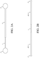
- FIG. 2A An illustrative embodiment of such a microfluidic circuit is provided by FIG. 2A in which the microfluidic channel includes a "Small section” representing the first channel section ( 1 ) and a "Large section” representing the second channel section ( 2 ) into which the fluid flows after exiting the first channel section.
- the fluid encounters the majority, and in some embodiments at least 60%, 70%, 75%, 80%, 85%, 90%, 95%, or 98% and less than 100% (preferably at least 80%, 85%, 90%, or 95%) of the resistance encountered as it traverses the microfluidic channel (and/or microfluidic circuit; i.e., including at least the first channel section ( 1 ) and second channel section ( 2 ) but also, in some embodiments, at least the inlet and in some embodiments also including the outlet). It is during the flow of fluid through the second channel section ( 2 ) that image acquisition occurs, e.g., specifically as the fluid traverses the optically clear subsection of this second channel section.
- the second channel section ( 2 ) may also be completely optically clear, i.e., optically clear along its entire length.
- the microfluidic viscometer assembly comprises: a) a microfluidic cartridge comprising: a first channel architecture comprising at least two microfluidic circuits, each microfluidic circuit comprising an inlet, a microfluidic channel comprising a first channel section having a first diameter and an end in direct fluidic communication with the inlet, a second channel section having an optically clear channel section and a second diameter greater than the first diameter, wherein the second channel is in direct fluidic communication with the first channel section at an end opposite the inlet, and, an outlet in fluid communication with the second channel section at an end opposite the first channel section, wherein the first channel section provides resistance to the fluid as it traverses the microfluidic channel that is at least 60%, 70%, 75%, 80%, 85%, 90%, 95%, or 98% (preferably at least 80%, 85%, 90%, or 95%) and less than 100% of
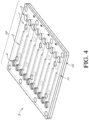
- FIG. 4 An illustrative embodiment of such a cartridge is provided by FIG. 4 .
- the illustrative cartridge ( 5 ) therein can comprise a top ( 11 ) and bottom ( 12 ) layer of material (e.g., plastic), and multiple microfluidic circuits ( 10 ), with ten shown in this embodiment.
- Each microfluidic circuit ( 10 ) comprises an inlet ( 3 ), a microfluidic channel comprising a higher-resistance first channel section ( 1 ), a lower-resistance second channel section ( 2 ), and an outlet ( 4 ).
- the microfluidic circuits may be fabricated by any of the methods available to those of ordinary skill in the art.
- a microfluidic viscometer assembly comprises a microfluidic cartridge comprising at least one and typically at least two microfluidic circuits, each comprising at least one microfluidic channel, wherein each microfluidic channel comprises multiple sections including at least a first higher-resistance and second lower-resistance section as described above, wherein the first channel section provides the majority of the resistance a fluid encounters while traversing said microfluidic channel, and at least a third channel section (also a lower-resistance section), wherein the second and third channel sections are positioned on either side of the first channel section, and where at least one or both of the second and/or third channel sections are at least partially optically clear (e.g., transparent; an optically clear subsection) such that the movement of the fluid can be monitored visually through the optically clear subsection to capture images of the fluid as it traverses the microfluidic channel (e.g., at a fluid-air interface between the fluid and air in that optically clear section); an optically clear (e.g
- the microfluidic viscometer apparatus can comprise a microfluidic cartridge comprising at least one microfluidic channel (e.g., as part of a microfluidic circuit) including a first channel section of a first diameter, and second and third channel sections having diameters greater than that of the first diameter and including at least one optically clear subsection, wherein the first channel section is positioned between the second and third channel sections, and wherein the fluid encounters higher resistance in the first channel section relative to the second and/or third channel sections.
- a microfluidic cartridge comprising at least one microfluidic channel (e.g., as part of a microfluidic circuit) including a first channel section of a first diameter, and second and third channel sections having diameters greater than that of the first diameter and including at least one optically clear subsection, wherein the first channel section is positioned between the second and third channel sections, and wherein the fluid encounters higher resistance in the first channel section relative to the second and/or third channel sections.
- the resistance encountered by the fluid in the first channel section accounts for the majority, and in some embodiments at least 60%, 70%, 75%, 80%, 85%, 90%, 95%, or 98% and less than 100% (preferably at least 80%, 85%, 90%, or 95%) of the resistance encountered as it traverses the microfluidic channel (and/or microfluidic circuit; i.e., including at least the first ( 1 ) and second ( 2B-2 ) channel sections (or in the case of a "reverse" application the first large channel section ( 2B-1 )) but also, in some embodiments, at least the inlet ( 3 ) and in some embodiments also including the outlet ( 4 )).
- FIG. 2B An illustrative embodiment of such a microfluidic circuit is provided by FIG. 2B in which the microfluidic channel includes a "Small section” representing the first channel section ( 1 ) (the higher-resistance section) and "Second large channel section” ( 2B-2 ), which is a lower-resistance section relative to the first channel section, into which the fluid flows after exiting the first channel section.
- a "Small section” representing the first channel section ( 1 ) (the higher-resistance section)
- “Second large channel section” 2B-2
- the fluid encounters the majority, and in illustrative embodiments at least 60%, 70%, 75%, 80%, 85%, 90%, 95%, or 98% and less than 100% (preferably at least 80%, 85%, 90%, or 95%, or at least 80% and less than 100%) of the resistance encountered by the fluid as it traverses the microfluidic channel is encountered in the first channel section ( 1 ).
- another (or third) section ( 2B-1 also called the "first large section”
- a lower-resistance section relative to the first channel section ( 1 ) is present between the inlet ( 3 ) and the first channel section ( 1 ) (also called the "small channel section").
- the second large channel section ( 2B-2 ) represents the lower-resistance channel section into which the fluid flows after exiting the higher-resistance first channel section ( 1 ). It is during the flow of fluid through this second large channel section ( 2B-2 ) (also called the "second large section") that image acquisition occurs, specifically as the fluid traverses the at least partially optically clear subsection of the second large channel section ( 2B-2 ) (the subsection being relevant where the second channel section is not completely optically clear).
- the fluid can flow from the inlet towards the outlet ( 4 ), or in "reverse" embodiments, fluid may enter the microfluidic circuit through the outlet, then traverse the second large channel section ( 2B-2 ), then the small channel section ( 1 ), then the first large channel section ( 2B-1 ), exit the device through the inlet ( 3 ).
- the microfluidic viscometer assembly can comprise: a) a microfluidic cartridge comprising a channel architecture (i.e., as "alternative" channel architecture) comprising at least one and typically at least two microfluidic circuits, each microfluidic circuit comprising an inlet, an outlet, at least one microfluidic channel comprising at least three sections (e.g., a small channel section ( 1 ) and two large channel sections ( 2B-1 and 2B-2 ) (illustrated in FIG. 2B ), wherein: the first channel section (e.g., 1 in FIG.
- a channel architecture i.e., as "alternative” channel architecture
- each microfluidic circuit comprising an inlet, an outlet, at least one microfluidic channel comprising at least three sections (e.g., a small channel section ( 1 ) and two large channel sections ( 2B-1 and 2B-2 ) (illustrated in FIG. 2B ), wherein: the first channel section (e.g., 1 in
- the second large section (e.g., 2B-2 ) at opposite ends is in direct fluidic communication with the first channel section (e.g., 1 ) and the outlet (e.g., 4 ), and includes an optically clear channel subsection, or is completely optically clear;
- the first large section (i.e., third channel section; e.g., 2B-1 ) is in direct fluidic communication with the inlet (e.g., 3 ); and, the first channel section (e.g., 1 ) provides a resistance that is at least 60%, 70%, 75%, 80%, 85%, 90%, 95%, or 98% and less than 100% (preferably at least 80%, 85%, 90%, or 95%, or at least 80% and less than 100%) of the combined resistance applied to, or encountered by, a fluid traversing, the microflui
- microfluidic circuits i.e., including at least the first channel section ( 1 ) and second channel section ( 2 ) but also, in some embodiments, at least the inlet and in some embodiments also including the outlet); and an outlet (e.g., 4 ) in fluid communication with the second large channel section ( 2B-2 ) at an end opposite the first channel section (1); b) an image recording system optically connected to the optically clear channel section of each of the at least one or at least two microfluidic circuits; and, c) a pressure control unit configured to deliver fluid into each of the at least one or at least two microfluidic circuits, and, in illustrative embodiments at a constant pressure (including as part of a pressure ramp protocol).
- the cartridge can comprise multiple microfluidic channels and/or microfluidic circuits.
- the cartridge can take the form shown in FIG. 4 , but in which the microfluidic channels and/or circuits include the three sections described herein, e.g., as illustrated as parts 2B-1, 1, and 2B-2 in FIG. 2B .
- the microfluidic viscometer apparatus assembly further comprises a temperature control unit that serves to control the temperature of the cartridge(s) and the one or more microfluidic circuits and microfluidic channels.
- a temperature control unit that serves to control the temperature of the cartridge(s) and the one or more microfluidic circuits and microfluidic channels.
- Illustrative embodiments of such microfluidic viscometer assemblies are provided by FIGS. 1 , 5 , and 6 .
- the image recording system operates by capturing images of the fluid as it traverses the microfluidic channel and/or microfluidic circuit (typically the optically-clear subsection of a lower-resistance section), comparing those images and thereby determining the viscosity and/or other properties of the fluid.
- each microfluidic channel and/or microfluidic circuit comprises at least one section through which the fluid flows and encounters a first resistance higher than a second resistance encountered in a subsequent section through which the fluid is moving.
- the images obtained are of the fluid (specifically, in some embodiments, the fluid-air interface) as it traverses a section exhibiting lower resistance to the flow of the fluid as compared to the immediately preceding higher-resistance section through which the fluid flowed.
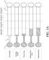
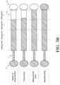
- Microfluidic channels comprising first and second channel sections wherein the resistance is higher in the first channel section than the second channel section are shown in shown in FIG. 2A (i.e., higher resistance small channel section (1), lower resistance large section ( 2 )); FIG.
- FIGS. 3A , 3B 3C , and 3D i.e., higher resistance first channel section (1), lower resistance second channel section ( 2 )
- FIGS. 3A , 3B , AND 3C i.e., higher resistance first channel section (1), lower resistance second channel section ( 2 )
- FIG. 3D i.e., higher resistance first channel section (1), lower resistance second channel section ( 2B-2 )
- the fluid (represented by hatch pattern shading in these illustrations) can be initially loaded into the inlet (3), thereby "priming" the microfluidic channel (e.g., fluid is allowed to fill the higher resistance first channel section ( 1 ), and enter but not fill the lower-resistance second channel section (2)).
- the microfluidic channel is then pressurized to begin pushing the fluid through the microfluidic channel.
- a first image can be acquired at a first point ("Measurement 1" or "first measurement”; e.g., once the fluid has traversed approximately 25% of the distance of the second channel section, FIG. 3A ).
- the microfluidic channel is then depressurized in preparation for the next measurement.
- the microfluidic channel is then pressurized again and an additional image obtained at the next selected point ("Measurement 2" or "second measurement”; e.g., at the 50% point of the second channel section).
- This process can be repeated until a sufficient number of images are obtained (e.g., "Measurement 3" or third measurement, "Measurement 4" or fourth measurement, etc. in FIGS. 3A and 3B ).
- images are obtained at times t 0, t 1, t 2, t 3, t 4, etc., respectively).
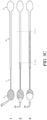
- FIG. 3C illustrates an embodiment where a first measurement and a second measurement are taken at times t 0 and t 1 , respectively.
- the images are then compared using a processor in order to determine the velocity at which the fluid traversed the second channel section of the microfluidic channel, and the viscosity determined.
- a processor can be applied to determine the rate at which the fluid traversed the microfluidic channel and, thereby, the viscosity and/or other properties of the fluid can be determined.
- FIG. 3D illustrates the flow of fluid through an exemplary microfluidic cartridge comprising a microfluidic channel (or microfluidic circuit) having at least three section where the majority of the resistance the fluid encounters while traversing the microfluidic channel is in one of those sections (a higher-resistance section) which a fluid flows through before entering a section of lower resistance.
- a microfluidic cartridge comprising a microfluidic channel (or microfluidic circuit) having at least three section where the majority of the resistance the fluid encounters while traversing the microfluidic channel is in one of those sections (a higher-resistance section) which a fluid flows through before entering a section of lower resistance.
- the fluid can be loaded into the input (3) of the microfluidic circuit, and pressure applied to push the fluid through the microfluidic channel (here, the lower-resistance first large channel section 2B-1).
- the fluid then flows through the higher-resistance channel section (1), and then into the lower-resistance second large channel section (2B-2).
- Either or both of lower-resistance large sections 2B-1 and 2B-2 can comprise at least one optically clear subsection, or may be completely optically clear. Images of the fluid-air interface within a lower-resistance section (e.g., the second large channel section (2B-2)) are obtained at an initial time point (t 0 ) and at least one other time point (t 1 ), and compared.
- the images are then compared using a processor in order to determine the velocity at which the fluid traversed the lower-resistance second large channel section (2B-2) of the microfluidic channel, and the viscosity determined.
- a processor can be applied to determine the rate at which the fluid traversed the microfluidic channel and, thereby, the viscosity and/or other properties of the fluid can be determined.
- the microfluidic viscometer assembly can include a cartridge comprising multiple microfluidic channels and/or microfluidic circuits.
- FIG. 4 illustrates one such exemplary microfluidic cartridge comprising multiple microfluidic circuits (10; in this embodiment, ten microfluidic circuits are illustrated) that each comprise an inlet (3), a microfluidic channel comprising a higher-resistance first channel section (1), and a second lower-resistance section (2), and an outlet (4) through which the fluid can exit the microfluidic circuit.
- the fluid can be introduced into the microfluidic channel through the outlet, traverse the microfluidic channel in the "reverse” direction, and exit the microfluidic channel through the inlet.
- the majority of the resistance a fluid traversing the same is encountered in the first channel section ( 1 in FIG. 4 ) of the microfluidic channel.
- Multiple images are captured of the fluid as it traverses the lower-resistance section ( 2 in FIG. 4 ) following the higher-resistance section, and can be obtained simultaneously for some or all of the fluids traversing different microfluidic channels in a cartridge.
- the images obtained for a particular fluid can then be compared, as described in greater detail below, in order to ascertain the viscosity and/or other property of each fluid being tested in each microfluidic circuit.
- each microfluidic circuit may be the same or different, and one or some of the microfluidic circuit(s) can also include one or more control (e.g., reference) fluids, although in certain illustrative embodiments, there are no control or reference fluids loaded into a cartridge.
- control e.g., reference
- the microfluidic channel(s) of the microfluidic viscometer include at least two sections where at least one of those sections, sometimes called herein the "first channel section,” “small section,” “resistance section,” “relatively high resistance section,” or “high resistance section,” provides the majority of the resistance encountered by a fluid as it traverses the microfluidic channel (e.g., the first channel section (1) ("Small section") of the exemplary microfluidic channel illustrated in FIG. 2A and in FIG. 2B ). These sections provide the majority of the resistance encountered by the fluid as it traverses the microfluidic channel and/or microfluidic circuit.
- microfluidic channels should be designed such that the flow is one dimensional from the inlet to the outlet (e.g., through the first channel section (small section)), and entrance effects (i.e., resistance encountered as the fluid enters the microfluidic circuit) are negligible.
- a range of lengths and widths can be used for the channels and sections thereof, of a microfluidic cartridge herein provided that the majority (or in some embodiments, at least 60%, 70%, 75%, 80%, 85%, 90%, 95%, or 98% (preferably at least 80%, 85%, 90%, or 95%, and less than 100%, or at least 80% and less than 100%) of the resistance in a microfluidic circuit is provided by this first channel section (small section; 1 in FIGS. 2A and 2B ) .
- the first channel section (small section) can have a height (h) of about 30 um (i.e., 27-33 um), a width of about 500 um (i.e., 494-501 um), and a length of about 1cm (i.e., 0.97 cm); the height/width (h/w) aspect ratio of the first channel section of this exemplary microfluidic circuit was 0.06.
- the h/w aspect ratio for the first channel section can be, for instance, less than 0.2, or in illustrative embodiments less than 0.1, such as any of 0.09, 0.08, 0.07, 0.06, 0.05, 0.04, 0.03, 0.02, or 0.01, or between 0.2 or 0.1 on the high end and 0.09, 0.08, 0.07, 0.06, 0.05, 0.04, 0.03, 0.02, or 0.01 on the low end.
- the section(s) providing lower resistance (large section(s)) in the Examples which includes the larger section to which the image recording system is optically connected (which can be called herein, the "second channel section,” “viewing section,” or “fluid speed measuring section”) have a height (h) and width (w) of about 1000 um (i.e., height: 910-960 um and width: 980-1100 um), and a length of about 3cm (i.e., 2.7 cm), such that the h/w aspect ratio of the lower resistance section is 1.
- the h/w aspect ratio for the lower resistance can be, for instance, between 0.5 and 1.5, 0.75 and 1.25, 0.8 and 1.2, 0.9 and 1.1, or 0,95 and 1.05, but in any event is greater than that of the higher-resistance large section(s).
- a second and third channel section e.g., first and second large sections (e.g., 2B-1 and 2B-2 as illustrated in FIGS. 2B and 3D ) are positioned on either side of the first channel section (small section, 1 in FIGS.
- the dimensions of the two large sections can, in illustrative embodiments, and in some preferred embodiments, be the same to avoid capillary effects that could occur if those dimensions differed.
- the microfluidic channels and/or sections thereof may be of many different shapes (e.g., circular, oval triangular, square, rectangle), these are typically constructed as rectangular or trapezoidal channels.
- the lower-resistance (large) sections of the microfluidic channels can be circular, the section(s) (small section) providing the higher resistance to the fluid is typically not circular in shape.
- the different sections of the microfluidic channel(s) are typically the same shape but can differ, and in one illustrative embodiment, have a rectangular shape.
- “diameter” means “effective diameter”, or “hydraulic diameter”, for embodiments having channels or sections therein, that have a shape other than circular. It is important, and preferred that, in whatever form the channels take and/or are constructed, the microfluidic circuit, and at least the microfluidic channel, provides laminar flow conditions and uniform flow to avoid turbulent flow and/or vortex formation therein as the fluid traverses the microfluidic channel(s).
- the inlet(s) and outlet(s) were circular (5 mm diameters), and between ten and 30 ul are typically loaded into the inlet for analysis, but this could vary as may be determined by those of ordinary skill in the art.
- the microfluidic circuits and microfluidic channels may be prepared from any suitable material such as plastic.
- the microfluidic circuit and microfluidic channel can be fabricated using a soft lithography technique.
- the cartridges can be injection molded using a suitable plastic.
- the microfluidic circuit(s) can be fabricated in or on a top layer of plastic (top layer 11 ) and bonded to a second flat piece (bottom layer 12 ) to form the cartridge body.
- the microfluidic circuit can be manufactured upon, within, or as the top layer 10 .
- a bottom layer such as 12 in FIG. 4 is not included.
- the microfluidic channel(s) should be non-deformable, meaning, e.g., that it does not expand in a manner that affects the viscosity measurement when, for instance, high pressures are used, and/or that the microfluidic channels are not comprised of an elastomeric material.
- the microfluidic circuits may be fabricated by molding (e.g., injection molding), engraving, microcontact printing, additive manufacturing (e.g., 3D printing), hot embossing, laser photoablation, micro-milling, etching (e.g., wet, dry (e.g., physical, dry), or reactive ion etching), or other suitable technique.
- the microfluidic circuits and/or microfluidic channels may be made of silicon, glass, a ceramic material, thermoplastic polymer (e.g., polystyrene (PS), polyether ether ketone (PEEK), polyethylene terephthalate (PET), polyvinyl chloride (PVC), polymethylmethacrylate (PMMA), cyclic olefin copolymer (COC), polycarbonate (PC), and/or PEI (polyetherimide)), and/or a thermoset (e.g., thermoset polyester (TPE).
- PS polystyrene
- PEEK polyether ether ketone
- PET polyethylene terephthalate
- PVC polyvinyl chloride
- PMMA polymethylmethacrylate
- COC cyclic olefin copolymer
- PC polycarbonate
- PEI polyetherimide
- TPE thermoset polyester
- Other techniques and/or materials may also be suitable, as may be determined by those of ordinary
- the exemplary microfluidic viscometer assemblies illustrated in FIGS. 1 , 5 and 6 include, but are not limited to, an image recording and processing system, a pressure control unit, and a temperature control unit.
- the image recording and processing system can comprise at least a light source, a recording device (e.g., a camera), and an image processor communicably coupled to the imaging device that determines a viscosity and/or other properties of the fluid based on the two or more images using one or more algorithms (such as, e.g., those described below for Newtonian and non-Newtonian fluids).
- the light source and recording device are typically positioned to capture two or more images of the fluid-air interface present at the front (or leading) edge of the fluid (i.e., the fluid-air interface) as it traverses the microfluidic channel (e.g., above the cartridge (5) (as illustrated in FIGS. 5-8 )), in some embodiments above the lower-resistance section (e.g., the optically clear section thereof) of the microfluidic channel ( FIG. 4 )). In some embodiments, as illustrated in FIGS.
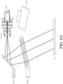
- the image recording portion of the system can comprise a camera (6-1), a small Plano convex lens and aperture (6-1a), a mirror (6-4), a large Plano convex lens (6-5), and a diffuse light source (e.g., diffused light-emitting diode panel (6-6)), positioned in so as to illuminate and provide contrast at the fluid-air interface in the optically-clear section of a microfluidic channel and such that each image of the fluid-air interface is transmitted to and captured by the camera for processing by the image processor (6-2).
- a diffuse light source e.g., diffused light-emitting diode panel (6-6)
- Suitable, exemplary image processors can include, for instance, a general purpose computer comprising Matlab (Mathworks, Boston, MA), Image J (an open source image analysis system), or other system as may be available to those of ordinary skill in the art.
- the image processor is integrated into or wirelessly connected to the recording device (e.g., digital camera).
- the recording device e.g., digital camera.
- microfluidic viscometer can include a smartphone, a tablet, a personal digital device, a computer pad, a netbook, and/or a computer having imaging processor and/or digital camera integrated therein, or a camera per se.
- the camera may be one of a Charge-Coupled Device (CCD) or Complimentary Metal-oxide Semiconductor (CMOS) camera.
- Suitable light sources can include, in some embodiments, at least one Light Emitting Diode (LED) or LED panel.
- the at least one LED may be a colored LED.
- An excitation filter may filter the at least one LED.
- At least one such light source e.g., LED or LED panel
- the system can also include an emission filter for filtering light entering the camera.
- the pressure control unit provides a known pressure at the inlet of the cartridge that pushes the fluid through the microfluidic channels at a constant rate.
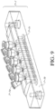
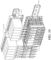
- the pressure control unit comprises a manifold (part 7-1 in FIG. 9 ) connected to the microfluidic circuits (e.g, within the cartridge, and sealing it) ( FIGS. 6 , 9-10 ) connected to a pressure architecture comprising a distribution manifold (7-2) that holds the pressure regulators in place, proportional regulators (7-3), and one or more programmable logic controllers (PLC such as din-rail mounted modules (7-4)) ( FIG.
- GUI graphical user interface
- a pneumatic manifold can clamp down over the cartridge inlets to seal the same.
- Tubing connected to the ten pressure regulators can be fed into the manifold to supply pressure to each microfluidic circuit and/or microfluidic channel.
- valves can be used to shut off pressure to individual microfluidic circuits (e.g., if each microfluidic circuit does not have its own pressure regulator). In preferred embodiments, however, pressure can be controlled for each separate microfluidic circuit, and valves are not necessary.
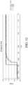
- the pressure control unit of the microfluidic viscometer was capable of providing pressures approximately equal to the target pressure in two separate channels simultaneously ("ch2 avg.” and "ch3 avg.”).
- the target voltage of 2.000 volts recorded an average input voltage of 1.954 volts, with channel 1 average voltage of 1.950 volts and channel 2 average voltage of 2.003 volts.
- the pressure control unit or pressure control system (PCS) provided similar plots at other voltage inputs.
- a suitable pressure control unit should be able to apply a controllable constant pressure (or a pressure ramp) of from about zero to 100,000 Pa (e.g., about any of 1000, 2000, 3000, 4000, 5000, 6000, 7000, 8000, 9000, 10000, 11000, 12000, 13000, 14000, 15000, 16000, 17000, 18000, 19000, 20000, 30000, 40000, 50000, 60000, 70000, 80000, 90000, or 100000, or between about 1000 to about 20,000 Pa, and/or any Pa value in between, such as those used in the Example) to a particular microfluidic circuit and/or microfluidic channel (i.e., the fluid therein), that pressure being the same or different as that being applied in any other microfluidic circuit and/or microfluidic channel.
- a controllable constant pressure or a pressure ramp
- an illustrative pressure control unit should be capable of applying different constant pressures (or pressure ramps) to the various microfluidic channels being used (e.g., being contained within a cartridge).
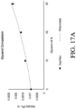
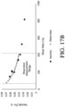
- the constant pressure is controllably variable (i.e., tunable) in order to generate particularly informative viscosity curves (e.g., the "Viscosity Data" shown in FIGS. 17A and 17B and carried out in the examples (e.g., Tables 1-5 )).
- Viscosity Data shown in FIGS. 17A and 17B and carried out in the examples (e.g., Tables 1-5 )
- the manifold can provide an individual linkage (and therefore pressure control) between a particular microfluidic channel and the pressure control unit such that the pressure being applied to each can be the same or different depending on the particular application (e.g., using tubing connecting individual microfluidic channels to the pressure control unit ( FIG. 6 )).
- the pressure control unit can be programmed (or can be programmable) to drive fluid into each of the microfluidic circuits to deliver a constant pressure thereto, wherein the pressure is substantially the same, the same, or different in each microfluidic circuit.
- the pressure may also be modified over time within a single microfluidic circuit, as when a user applies incorporates a pressure ramp into a method for using the microfluidic viscometer.
- the pressure control unit is automatically controlled (e.g., using software) such that a computer central processing unit is programmed, and can be controlled by a user, such as through a graphical user interface, to perform this function.
- the pressure control unit is adapted for, configured to, and/or operable to provide a change in pressure over time to a connected microfluidic circuit(s), and in some embodiments to each microfluidic circuit of an assembly of at least two microfluidic circuits independently and in some embodiments simultaneously.
- such change in pressure can be preset, for example by a user.
- the pressure control unit controls the pressure applied to each of the microfluidic circuits, or wherein two or more pressure control units each separately control the pressure applied to at least two of said microfluidic circuits.
- Suitable, exemplary pressure control units can include, for instance, the Microfluidic Pressure controller OB1 MK3 (Elveflow), among others as may be available to those of ordinary skill in the art.
- the temperature control unit controls the temperature of the cartridge and/or microfluidic channel and/or microfluidic circuit. Temperature is an important factor that affects the viscosity of the fluid and it is important that the temperature of the fluid remain constant as the fluid is traversing the microfluidic circuit.
- Suitable temperature control units that can be used in the microfluidic viscometers disclosed herein can include, for instance, the illustrative temperature control unit illustrated in FIG. 13 comprising a temperature controlled thermal block that can include a Peltier device, a heat spreader plate or heat transfer pad, a temperature controlled circulating fluid, and/or the like. The illustrative example shown in FIG.
- the thermal block 13 includes, for instance, a cartridge (5) on a heat spreader plate (8-1) upon a Peltier device (heating/cooling device) (8-2), a mount platform (8-3) supporting the heat spreader plate, a heat sink (finned and fan for active cooling) (8-4), and a duct for the fan outlet (to reduce recirculation) (8-5).
- the thermal block may be part of a thermal cycler having at least one thermally controlled surface.
- the temperature control unit comprises a heat spreader plate upon which a cartridge may be positioned, a Peltier (heating/cooling device) beneath the heat spreader plate, a duct for an inlet fan, as well as a heat sink (e.g., finned) and fan for active cooling.
- a heat spreader plate upon which a cartridge may be positioned
- a Peltier heating/cooling device
- a duct for an inlet fan as well as a heat sink (e.g., finned) and fan for active cooling.
- a heat sink e.g., finned
- the microfluidic viscometer can include, and preferably includes, a temperature control unit that controls the temperature of the microfluidic cartridge, optionally wherein the microfluidic cartridge contacts a conductive thermal plate having a temperature controlled by the temperature control unit.
- the temperature control unit is automatically controlled (e.g., using software).
- the temperature control unit is adapted for, configured for, and/or effective for maintaining the temperature of the microfluidic circuits in a microfluidic cartridge, or wherein two or more temperature control units separately maintain the temperature of at least two of said microfluidic circuits.
- the Meerstetter TEC-1090-HV may be used.
- Other temperature control units may also be suitable, as may be determined by those of ordinary skill in the art.
- the microfluidic viscometer may be encased by, for instance a hard shell or case around some or all of the components.
- FIGS. 15A-15B provides an example of an integrated microfluidic viscometer assembly or system in which the image recording and processing system, pressure control unit, and temperature control unit are essentially hidden from view of the user by a solid case or external shell (9).
- the cartridge comprising the microfluidic circuit(s) can be inserted into the device for analysis, and removed from the device following analysis, using a cartridge shuttle (11).
- the cartridge may be held in place once inserted into the device by connecting it to the manifold, in some instances using a clamp (10).
- the hard shell or case (9) may be constructed of any suitable material such as hard plastic commonly used by those of skill in the art to house analytical instruments as shown in FIG. 15B .
- such an integrated microfluidic viscometer system can also comprise or provide for using multiple cartridges (e.g., two, four, eight, 16, 32 or 64 cartridges), each optionally comprising at least one, and typically two or more microfluidic circuits, and the option to test the same or different fluids in each cartridge and/or microfluidic circuit at the same or different pressures and/or temperatures.
- cartridges e.g., two, four, eight, 16, 32 or 64 cartridges
- Other versions of such integrated microfluidic viscometer systems may also be suitable, as may be determined by those of ordinary skill in the art.
- This disclosure also relates to methods for using a microfluidic viscometer assembly disclosed herein to determine the viscosity and/or other property of a fluid or a collection of fluids (e.g., using a cartridge comprising multiple microfluidic channels and/or microfluidic circuits (e.g., as illustrated in FIGS. 3A-3D )).
- this disclosure relates to microfluidic viscometer instruments or apparatuses onto which at least one such microfluidic cartridge can be loaded, and which include an image recording and optionally analysis system (e.g., light, camera, optional image processor), a pressure control unit, and typically also comprising a temperature control unit (e.g., FIGS. 1 , 4-5 ) .
- image recording and optionally analysis system e.g., light, camera, optional image processor
- a pressure control unit e.g., a pressure control unit
- typically also comprising a temperature control unit e.g., FIGS. 1 , 4-5
- one or more cartridges are loaded onto a microfluidic viscometer either before or after performing a fluid loading step of a method provided herein, and typically before applying a pressure to a microfluidic circuit (e.g., within a cartridge), and is removed from the viscometer assembly after the method is performed.
- the cartridge for example, can rest on, and is more typically secured on a platform on a viscometer instrument or apparatus as part of a viscometer assembly, for example on a heat spreader plate of a temperature control unit.
- a cartridge can be used to screw a cartridge into a securing structure connected to a heat spreading plate or other platform on the viscometer.
- the cartridge snaps into a cartridge securing mechanism of a viscometer and can be released from the securing mechanism, such as by pressing a lever using for example, a spring loaded mechanism.
- the cartridges are disposable and can be disposed of after use, thereby eliminating the need for cleaning procedures.
- a method herein can included, disposing of the microfluidic cartridge and providing another disposable microfluidic cartridge and repeating the method.
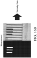
- FIGS. 16A-16B provides an exemplary microfluidic viscometer ( FIG. 16A ) and an image captured from a cartridge while performing a method using the microfluidic viscometers described herein, such as that exemplified in FIG. 16A .
- the exemplary microfluidic viscometer assembly of FIG. 16A includes an image recording and processing system, a pressure control unit, a temperature control unit, and a cartridge comprising multiple microfluidic circuits (i.e., a multiplexed cartridge) (see also the exemplary cartridge illustrated in FIG. 4 ).
- Viscosity Data shown in detail in NeoVisc data in FIG.
- test fluids were introduced into some or all of the microfluidic circuits of the cartridge, processed at user-selected pressures and/or temperatures, and images of the fluid-air interface captured ("Measurement" FIG. 16B ) and processed as the fluid traversed the optically clear sections of the microfluidic channels of the microfluidic circuits. As shown in the "Measurement" panel ( FIG.
- test fluids traversed the microfluidic channel (i.e., the optically clear section or subsection thereof) to point 197, 207, and 211, respectively, showing, e.g., that the three test fluids exhibit different velocities through the microfluidic circuits.
- the "Measurement” images were then processed into data and presented in a usable format ("Viscosity Data", shown in detail in NeoVisc data in FIG. 17B ). More details regarding this example is provided in the Examples section below.
- a small volume of a fluid sample is initially loaded into a cartridge containing a microfluidic channel.
- the volume of fluid sample loaded can be 1-100ul, 2.5-50ul, 5-50ul, 5-25ul, 5-10ul, 10-50ul, or 10-25ul.
- two to seven seconds can be provided for the fluid to propagate into the horizontal portion of the capillary and image capture is initiated about five seconds after that point (e.g., about 10 seconds of start-up time is allowed before the velocity calculations are initiated).
- the user can pre-select a temperature and pressure ramp under which the analysis can proceed.
- the imaging device is typically positioned above an optically clear section of the microfluidic channel of lower resistance (e.g., the large section (2) of the microfluidic circuit illustrated in FIG. 2A , second large channel section (2B-2) of the microfluidic circuit illustrated in FIG. 2B ; large section (2) of the microfluidic circuit illustrated in FIGS. 3A-3B , second channel section 2 of the microfluidic circuit illustrated in FIG. 3C ; and the second large channel section ( 2B-2 ) of the microfluidic circuit illustrated in FIG. 3D ( 2A )).
- the large section (2) of the microfluidic circuit illustrated in FIG. 2A second large channel section (2B-2) of the microfluidic circuit illustrated in FIG. 2B
- large section (2) of the microfluidic circuit illustrated in FIGS. 3A-3B second channel section 2 of the microfluidic circuit illustrated in FIG. 3C
- second large channel section ( 2B-2 ) of the microfluidic circuit illustrated in FIG. 3D ( 2A ) the imaging device
- Two or more images of the fluid-air interface present between the fluid and the air in the microfluidic channel are then captured by the image recording device (e.g., camera), and those images processed by the image processor to determine the viscosity and shear rate of the fluid (this determination being dependent on the pressure, the dimensions of the microfluidic channels, and velocity of the fluid, as described in more detail below), along with other properties if desired.
- the image recording device e.g., camera
- the position of the fluid in the microfluidic channel is tracked by the image recording and processing system positioned above the cartridge, which records (e.g,. video) of fluid movement through the channel.
- the image recording and processing system detects the fluid-air interface and can apply a Hough transform to the edge of the fluid-air interface to determine the distance the interface has moved over time (i.e., the velocity of the fluid).
- An imaging algorithm incorporated into the image recording and processing system software can extract two or more images from the video, applies contrast, detect the fluid-air interface, and measure velocity. From the velocity profile, the software automatically calculates shear stress, apparent shear rate, apparent viscosity, true shear rate, and true viscosity.
- fluid velocity in the channel can be extrapolated from images (e.g., recorded video data).
- images e.g., recorded video data.
- two or more images are extracted at known time points, and the distance traveled by the fluid over a set time frame is measured.
- this technology can measure the viscosity of both Newtonian and non-Newtonian fluids.
- one or more flowmeters could also or alternatively be used to take measurements downstream of the outlet (e.g., not in the cartridge).
- a fluid sample can be loaded into the part labelled in most embodiments as the outlet (e.g., part 4 in FIGS. 2-4 ), moved into the microfluidic channel of the microfluidic circuit using constant pressure, through a lower-resistance large section (e.g., part 2 in FIG. 2A or 2B2 in FIG. 2B ) and then into a higher-resistance small section (e.g., part 1 in FIGS. 2A and 2B ), and tracked / imaged in a large channel (e.g. part 2 in FIG. 2A , 2B-1 or 2B-2 in FIG. 2B ) by identifying the 'trailing' fluid-air interface in the large channel typically after the small channel is filled with fluid, to measure viscosity as described above with respect to the tracking of the leading fluid-air interface.
- a lower-resistance large section e.g., part 2 in FIG. 2A or 2B2 in FIG. 2B
- the viscosity and shear rate for Newtonian and non-Newtonian fluids can be computed by the image data processor, also referred to herein as an image analysis processor, which can be part of the image analysis function, from the data captured (e.g., the velocity by which the fluid traversed the microfluidic channel) using the following non-limiting algorithms described here, among others.
- Such equations can be used for example, in embodiments, when the higher-resistance section of the microfluidic channel provides at least 80%, and in illustrative embodiments at least 85%, 90%, 95%, 98%, or 99% (preferably at least any of 80%, 85%, 90%, or 95%) of the resistance of the combined resistance of all of the microfluidic channels in a microfluidic circuit of any of the architectures provided herein.
- This equation for the geometric factor of a rectangular channel only applies if h «w, as is the case for the small microchannel.
- the geometric factor for the large channel is negligible compared to that of the small channel, so the total geometric factor for the system can be expressed by the equation above.
- capillary pressure is present when one fluid-air interface exists.
- ⁇ refers to the surface tension of the fluid
- cos ⁇ top refers to the contact angle of the fluid on the top surface of the channel
- cos ⁇ bottom refers to the contact angle of the fluid on the bottom surface
- cos ⁇ left refers to the contact angle of the fluid on the left wall
- cos ⁇ right refers to the contact angle of the fluid on the right wall.
- a positive capillary pressure corresponds to fluid resisting movement through the channel
- a negative capillary pressure corresponds to fluid being pulled through the channel.
- capillary pressure is considered negligible, however if the capillary pressure accounts for more than 20, 15, 10, 9, 8, 7, 6 or preferably about 5, or 5% of the driving pressure, then it should be accounted for.
- the term d (ln ⁇ 0 )/ d (ln ⁇ w ) must first be approximated by plotting apparent shear rate versus shear stress for a range of pressure drops, fitting an appropriate polynomial to the points, and differentiating. Then, the true shear rate, and subsequently the viscosity, can be found for each pressure drop.
- Information on injectability can be determined by measuring the viscosity of injectable solutions at relevant shear rates to determine if appropriate concentrations of active solution can be safely delivered into the body.
- Exemplary fluids that can be tested using the microfluidic viscometers disclosed herein can include but are not limited to protein solutions, biological samples (e.g., blood, synovial fluid, saliva, vitreous humor), foods (e.g., ketchup, mustard), cosmetics (e.g., creams such as shaving cream, lotions), pharmaceutical formulations, paints (e.g., colloidal suspensions admixed with polymers), inks, oils (e.g., engine oil), thickeners, petroleum products.
- biological samples e.g., blood, synovial fluid, saliva, vitreous humor
- foods e.g., ketchup, mustard
- cosmetics e.g., creams such as shaving cream, lotions
- pharmaceutical formulations e.g., colloidal suspensions admixed with polymers
- inks e.g., engine oil
- thickeners e.g., mineral oil
- the first channel section is considered the higher-resistance section and the second channel section is considered to be a lower-resistance section.
- the widths and/or heights are important to the function of each as a high-resistance or low-resistance section.
- the h/w ratio for the high-resistance section can be under 0.1, such as about 0.06.
- the first channel section provides at least 90% and less than 100%, optionally wherein the first section provides at least 95% and less than 100% of the combined resistance of the first and second channel sections, and/or of the entire microfluidic circuit, for a fluid traversing the microfluidic circuit.
- the first and second channel sections are directly fluidly connected without any intervening sections and/or parts. In some embodiments, the first and second channel sections form a straight fluidic flow path without a bend. In some embodiments, the microfluidic viscometer assembly does not comprise a glass capillary in fluid communication with the microfluidic circuits and/or microfluidic channels. It is also noted that, in some embodiments, a fluid may enter or exit the microfluidic circuit by either the inlet or the outlet (e.g., as in the "reverse" method described above).
- the microfluidic viscometer assembly can include a light source, optionally a diffuse light source, optically connected to the optically clear sections of the microfluidic channel.
- a single image recording system is positioned above all the microfluidic circuits, or a separate image recording system is positioned above each microfluidic circuit, which can also be referred to as a microfluidic channel circuit.
- the microfluidic viscometer assembly further includes an image analysis function comprising an image analysis processor comprising instructions to determine velocity of a fluid through each of the microfluidic circuits and to use said velocity to determine a viscosity of the fluid, optionally wherein the image analysis function is a computer program stored on a memory of a computer that is not physically associated with, or connect to the image recording system, or optionally any other physical component of the microfluidic viscometer assembly.
- the image analysis function is an automatic function because it is preprogrammed to run the program without further user intervention.
- the image analysis function further comprises instructions to calculate shear stress, apparent shear rate, apparent viscosity, true shear rate, and/or true viscosity of said fluid of a fluid in each of the microfluidic circuits.
- each microfluidic cartridge can include four to 36 of said microfluidic circuits, and optionally comprises 10 or 12 microfluidic circuits.
- the microfluidic cartridge is a disposable microfluidic cartridge, removably connected to a microfluidic instrument comprising the image recording system and pressure control unit.
- the microfluidic circuits of the microfluidic cartridge are formed in plastic that may be non-deformable.
- the walls of the first channel section and the second channel section are non-deformable, and have the same or different composition.
- this disclosure provides methods for determining the viscosity of a fluid using a microfluidic viscometer assembly disclosed herein, the method including determining the velocity at which said fluid is moving through said microchannel.
- such methods include:
- the methods include: introducing a first fluid into a first inlet to load the fluid into a first channel section of a first microfluidic circuit of a microfluidic cartridge comprising at least two microfluidic circuits, each microfluidic circuit comprising: i) an inlet; ii) at least one microfluidic channel comprising a first channel section having a first diameter and an end in direct fluidic communication with the inlet, and a second channel section having an optically clear channel subsection, or being completely optically clear, and having a second diameter greater than the first diameter, wherein the second channel section is in direct fluidic communication with the first channel section at an end opposite the inlet; and, iii) an outlet in fluid communication with the second channel section at an end opposite the first channel section; wherein the first channel section provides a resistance to a fluid traversing said microfluidic channel that is at least 80% and less than 100% of a combined resistance of the first and second channel sections, and/or of the microfluidic circuits; applying
- such methods include: a) introducing a first fluid into a first inlet to load the fluid into a first channel section of a first microfluidic circuit of a microfluidic cartridge comprising at least two microfluidic circuits, each microfluidic circuit comprising: i) an inlet; ii) an outlet; iii) at least one microfluidic channel comprising at least a first, second and third channel section, wherein: the first channel section is positioned between the second and third channel sections; the second channel section is in direct fluidic communication with the first channel section and the outlet, and includes an optically clear channel subsection, or is completely optically clear; the third channel section is in direct fluidic communication with the inlet; and, the first channel section provides a resistance that is at least 80% and less than 100% of the combined resistance encountered by a fluid traversing the first and second channel sections, or of the microfluidic circuits; and, the outlet is in fluid communication with the second channel section at an end of the microfluidic circuit opposite the first
- the method include removably connecting a microfluidic cartridge as disclosed herein to a microfluidic viscometer comprising: a pressure control unit, wherein the pressure control unit applies the constant pressure to said first channel section; and, an image recording system, wherein the image recording system captures images that are used to determine the velocity at which said fluid is moving through said second channel section.
- said microfluidic cartridge comprises microfluidic circuits comprising microfluidic channels including a least one section (e.g., the above-described first channel section) having a height less than 0.1 its width.
- the microfluidic viscometer and methods of use comprise and/or can be used to study Newtonian and/or non-Newtonian fluids.
- the fluid is an aqueous fluid, an oil-based fluid is not loaded into a microchannel, and/or an oil-aqueous fluid interface is not formed.
- the viscosity of multiple fluid samples of such fluids, the same or different are determined simultaneously.
- a control fluid is not loaded into a microfluidic circuit during the method.
- the velocity of a fluid is determined by extracting two or more images recorded by the image recording system, and comparing a fluid-air interface in each of said images.
- the methods include removing the microfluidic cartridge from the instrument after determining the viscosity of a first fluid. In some embodiments, the methods further include removably connecting another microfluidic cartridge to the instrument and repeating the method to determine the viscosity of a second fluid. In some embodiments, the method is first performed to determine the viscosity of at least two different fluids loaded into different microfluidic circuits of the microfluidic cartridge, and then is performed on at least two additional fluids loaded into the other microfluidic cartridge. In some embodiments, in addition to velocity, viscosity is determined using the pressure and dimensions of the first channel section, the second channel section, and optionally the third channel section, of the microfluidic channel.
- this disclosure provides a product(s) comprising at least two microfluidic viscometer microfluidic cartridges, each microfluidic cartridge comprising at least one microfluidic circuit through which said fluid can flow, each microfluidic circuit comprising: an inlet through which said fluid can be loaded into the channel, a first channel section having a first diameter, and second optically clear channel section having a second diameter greater than the first diameter, wherein the walls of the first channel section and the second channel section are comprised of the same or different non-deformable composition and wherein the first channel section provides a resistance that is at least 80% and less than 100% of a combined resistance of the first channel section and the second channel section; and, an outlet through which said fluid can exit the channel.
- such product can include at least two microfluidic viscometer microfluidic cartridges, each microfluidic cartridge comprising: at least one microfluidic circuit through which said fluid can flow, each microfluidic circuit comprising an inlet through which said fluid can be loaded into the microfluidic circuit; at least one microfluidic channel comprising a first channel section having a first diameter, a second and/or third channel section having a second diameter greater than the first diameter and optically clear subsection (or is completely optically clear) with diameter(s) greater than the first diameter and optionally the same as one another (i.e., the second and third channel sections have the same diameter), wherein the first channel section provides a resistance that is at least 80% and less than 100% of a combined resistance of the first, second and third channel sections, and wherein the walls of the first, second and third channel sections comprise the same or different non-deformable composition; and, an outlet through which said fluid can exit the channel.
- the product further comprises a computer program stored on a computer memory, wherein the computer program comprises instructions for performing an image analysis function to determine velocity of a fluid through each of the microfluidic circuits and to use said velocity to determine a viscosity of the fluid, optionally wherein the image analysis function is a computer program stored on a memory of a remote computer server.
- the computer program is accessible over the Internet or stored on a storage device.
- the product further comprises instructions for loading the microfluidic viscometer microfluidic cartridges into a microfluidic viscometer. Other embodiments are also contemplated by this disclosure, as may be determined by one of ordinary skill in the art.
- composition can comprise a combination means that the composition may comprise a combination of different molecules or may not include a combination such that the description includes both the combination and the absence of the combination (i.e., individual members of the combination).
- Ranges may be expressed herein as from about one particular value, and/or to about another particular value. When such a range is expressed, another aspect includes from the one particular value and/or to the other particular value. Similarly, when values are expressed as approximations, by use of the antecedent about or approximately, it will be understood that the particular value forms another aspect. It will be further understood that the endpoints of each of the ranges are significant both in relation to the other endpoint, and independently of the other endpoint. Ranges (e.g., 90-100%) are meant to include the range per se as well as each independent value within the range as if each value was individually listed. All references cited within this disclosure are hereby incorporated by reference in their entirety. Certain embodiments are further described in the following examples. These embodiments are provided as examples only and are not intended to limit the scope of the claims in any way.
- microfluidic viscometers described herein are capable of highly accurate, reproducible, low volume (e.g. 10 ⁇ L), and multiplexed viscosity measurements of both Newtonian and Non-Newtonian fluids.
- glycerol solutions and a model protein solution (BSA) ranging in concentration from 10-300mg/mL, both Newtonian fluids, were tested using the microfluidic viscometer and found to generate data that favorably compared to that obtained using conventional rheometer.
- a Non-Newtonian fluid polyethylene oxide (PEO) fluid was also tested at a range of shear rates between 200-2000/s, and similarly found to compare favorably a conventional rheometer.
- PEO polyethylene oxide
- a first channel section (1) also called a “small section” was in fluid communication with an inlet at one end and a second channel section (2), also called a large section, at its other end.
- This cartridge was tested using a system as shown in FIG. 16A (called NeoVisc in this Example).
- the first channel section had a height of about 30 um (i.e., 27-33 um), a width of about 500 um (i.e., 494-501 um), and a length of about 1cm (i.e., 0.97 cm); the h/w aspect ratio of this exemplary microfluidic circuit was 0.06.
- the second channel section had a height and width of about 1000 um (i.e., height: 910-960 um and width: 980-1100 um), and a length of about 3cm (i.e., 2.7 cm).
- the inlet and outlet holes were both 5mm in diameter.
- the fluid experiences capillary effects due to the surface tension of the fluid-air interface in the large channel.
- each experimental data point comprises an average of three runs using the NeoVisc and was compared against viscosity data collected from a commercially available rheometer instrument (DV2T by Ametek Brookfield).
- FIG. 17B data points were collected at eight different shear rates and similarly were compared against rheometer data. The rheometer data is limited because the instrument requires additional spindles to cover a wider shear rate range.
- a single solution of 30 weight % glycerol was run at three different driving pressures, and the distance traveled over time was measured to confirm linearity. Finally, in the plot for K vs.
- the microfluidic channels included three sections: a first channel section (1), also called a small section" providing the majority of the resistance encountered by the fluid as it moved through the microfluidic circuit positioned between two larger channels, a first large channel section (2B-1), also called a first large section, and a third channel section (2B-2), sometimes called a second large channel section, sharing equal geometries and producing less resistance to the fluid than the first channel section.
- a first channel section (1) also called a small section
- 2B-1 also called a first large section
- 2B-2 third channel section
- the first channel section (1) had a height of about 30 um (i.e., 30-32 um), a width of about 500 um (i.e., 498-504 um), and a length of about 1 cm (i.e., 0.99 cm); the h/w aspect ratio of this exemplary microfluidic circuit was 0.06.
- the two larger channel sections (2B-1 and 2B-2) had heights and widths of about 1000 um (i.e., first channel section: 910-980; second and third channel sections: 990-1100 um), and length of about 3 cm.
- the inlet and outlet holes were 1.5 mm in diameter.
- each experimental data point comprises an average of at least six runs and is compared against viscosity data collected from a commercially available rheometer instrument (DV2T by Ametek Brookfield).
- the PEO comparison data was collected at eight different shear rates and similarly compared against rheometer data.
- the rheometer data is limited because the instrument requires additional spindles to cover a wider shear rate range. Table 4 (data presented in FIG.
- a comparison to conventional rheometry was also performed using a fluid comprising bovine serum albumin (BSA) using Cartridge 2.
- BSA bovine serum albumin
- Each experimental data point comprises an average of at least six runs and is compared against viscosity data collected from a commercially available rheometer instrument (DV2T by Ametek Brookfield). The results are shown below and confirm that the microfluidic viscometer can be used for fluids comprising proteins. Table 6 (data presented in FIG.
Landscapes
- Chemical & Material Sciences (AREA)
- Health & Medical Sciences (AREA)
- Analytical Chemistry (AREA)
- General Health & Medical Sciences (AREA)
- Immunology (AREA)
- Biochemistry (AREA)
- Life Sciences & Earth Sciences (AREA)
- General Physics & Mathematics (AREA)
- Physics & Mathematics (AREA)
- Pathology (AREA)
- Dispersion Chemistry (AREA)
- Hematology (AREA)
- Clinical Laboratory Science (AREA)
- Chemical Kinetics & Catalysis (AREA)
- Physical Or Chemical Processes And Apparatus (AREA)
- Automatic Analysis And Handling Materials Therefor (AREA)
- Micromachines (AREA)
Applications Claiming Priority (3)
| Application Number | Priority Date | Filing Date | Title |
|---|---|---|---|
| US201862755320P | 2018-11-02 | 2018-11-02 | |
| EP19878746.7A EP3873668B1 (fr) | 2018-11-02 | 2019-11-01 | Ensemble viscosimètre microfluidique et procédé l'utilisant |
| PCT/US2019/059504 WO2020092982A1 (fr) | 2018-11-02 | 2019-11-01 | Viscosimètre micro-fluidique et ensemble et procédés d'utilisation associés |
Related Parent Applications (1)
| Application Number | Title | Priority Date | Filing Date |
|---|---|---|---|
| EP19878746.7A Division EP3873668B1 (fr) | 2018-11-02 | 2019-11-01 | Ensemble viscosimètre microfluidique et procédé l'utilisant |
Publications (2)
| Publication Number | Publication Date |
|---|---|
| EP4524546A2 true EP4524546A2 (fr) | 2025-03-19 |
| EP4524546A3 EP4524546A3 (fr) | 2025-05-14 |
Family
ID=70463328
Family Applications (2)
| Application Number | Title | Priority Date | Filing Date |
|---|---|---|---|
| EP19878746.7A Active EP3873668B1 (fr) | 2018-11-02 | 2019-11-01 | Ensemble viscosimètre microfluidique et procédé l'utilisant |
| EP24209311.0A Pending EP4524546A3 (fr) | 2018-11-02 | 2019-11-01 | Ensemble viscosimètre microfluidique et son procédé d'utilisation |
Family Applications Before (1)
| Application Number | Title | Priority Date | Filing Date |
|---|---|---|---|
| EP19878746.7A Active EP3873668B1 (fr) | 2018-11-02 | 2019-11-01 | Ensemble viscosimètre microfluidique et procédé l'utilisant |
Country Status (4)
| Country | Link |
|---|---|
| US (1) | US20210387193A1 (fr) |
| EP (2) | EP3873668B1 (fr) |
| ES (1) | ES3009541T3 (fr) |
| WO (1) | WO2020092982A1 (fr) |
Families Citing this family (6)
| Publication number | Priority date | Publication date | Assignee | Title |
|---|---|---|---|---|
| GB202011074D0 (en) * | 2020-07-17 | 2020-09-02 | Benson Viscometers Ltd | Viscosity measuring apparatus |
| US20220107255A1 (en) * | 2020-10-06 | 2022-04-07 | Abductive Services LLC | Goblet viscometer |
| US11994484B2 (en) * | 2021-03-25 | 2024-05-28 | The Regents Of The University Of California | Apparatus and method for single cell discrimination |
| WO2023021446A1 (fr) * | 2021-08-18 | 2023-02-23 | University Of Canterbury | Dispositifs microfluidiques, systèmes et procédés permettant de fournir une indication de rhéologie d'une substance |
| CN115436228A (zh) * | 2022-10-11 | 2022-12-06 | 山东大学 | 一种用于测量微升级液体样品粘度的系统及方法 |
| WO2024252353A1 (fr) | 2023-06-08 | 2024-12-12 | Janssen Research & Development, Llc | Viscosimètre microfluidique et procédés d'utilisation |
Family Cites Families (22)
| Publication number | Priority date | Publication date | Assignee | Title |
|---|---|---|---|---|
| FR2519760A1 (fr) * | 1982-01-14 | 1983-07-18 | Mobil Oil France | Appareil permettant la mesure et la visualisation de l'influence de la pression sur la viscosite des huiles |
| US4454751A (en) * | 1982-09-30 | 1984-06-19 | The United States Of America As Represented By The Secretary Of The Army | Extrudate swell rheometer and method of using same |
| US6953676B1 (en) * | 1992-05-01 | 2005-10-11 | Trustees Of The University Of Pennsylvania | Mesoscale polynucleotide amplification device and method |
| US5582705A (en) * | 1995-05-19 | 1996-12-10 | Iowa State University Research Foundation, Inc. | Multiplexed capillary electrophoresis system |
| US6428488B1 (en) * | 1997-08-28 | 2002-08-06 | Kenneth Kensey | Dual riser/dual capillary viscometer for newtonian and non-newtonian fluids |
| US6149815A (en) * | 1999-11-23 | 2000-11-21 | Sauter; Andrew D. | Precise electrokinetic delivery of minute volumes of liquid(s) |
| JP2004069397A (ja) * | 2002-08-02 | 2004-03-04 | Nec Corp | 分析チップおよび分析装置 |
| US7824620B2 (en) * | 2004-09-21 | 2010-11-02 | The Trustees Of The University Of Pennsylvania | Nano- and micro-scale structures: methods, devices and applications thereof |
| ITMI20061063A1 (it) * | 2006-05-31 | 2007-12-01 | Mindseeds Lab S R L | Metrodo e apparato pe rla selezione e la modifica di singole cellule e loro piccoli aggregati |
| EP2101917A1 (fr) * | 2007-01-10 | 2009-09-23 | Scandinavian Micro Biodevices A/S | Dispositif et systèmes microfluidiques et méthode d'exécution d'un essai |
| CN102124259B (zh) * | 2008-05-16 | 2015-12-16 | 哈佛大学 | 在包含微流体系统的流体系统中的阀和其它流动控制 |
| US7900503B2 (en) * | 2008-05-17 | 2011-03-08 | William Keith Leonard | Method of high throughput viscometry |
| GB2485965A (en) * | 2010-08-03 | 2012-06-06 | Univ Manchester | Rheometry apparatus for measuring the viscosity and elasticity of liquids |
| EP2646798B1 (fr) * | 2010-12-03 | 2017-06-28 | Cellply S.R.L. | Microanalyse d'une fonction cellulaire |
| MX349288B (es) * | 2011-01-21 | 2017-07-21 | Theranos Inc | Sistemas y metodos para maximizacion de uso de muestras. |
| US10209171B2 (en) * | 2013-12-09 | 2019-02-19 | Texas Tech University System | Smart phone based multiplexed viscometer for high throughput analysis of fluids |
| US20180021773A1 (en) * | 2014-07-25 | 2018-01-25 | Loughborough University | Assay devices, methods for carrying out assays, assay kits and method for manufacturing assay devices |
| US10598580B2 (en) * | 2014-12-19 | 2020-03-24 | Health Onvector Inc | Viscometers and methods of measuring liquid viscosity |
| GB201622024D0 (en) * | 2016-11-14 | 2017-02-08 | Inventage Lab Inc | Apparatus and method for large scale production of monodisperse, microsheric and biodegradable polymer-based drug delivery |
| DE102017008946A1 (de) * | 2017-09-23 | 2019-03-28 | Universität Greifswald | Verfahren zum Verformen von deformierbaren Körpern und Vorrichtungen dazu |
| WO2020136234A1 (fr) * | 2018-12-28 | 2020-07-02 | Astraveus | Dispositif et procédé de manipulation d'une suspension de particules |
| WO2021181342A1 (fr) * | 2020-03-11 | 2021-09-16 | Khalifa University of Science and Technology | Production de microbulles mono-dispersées à l'aide d'un générateur de bulles à micro-venturi modifié |
-
2019
- 2019-11-01 US US17/290,672 patent/US20210387193A1/en active Pending
- 2019-11-01 EP EP19878746.7A patent/EP3873668B1/fr active Active
- 2019-11-01 ES ES19878746T patent/ES3009541T3/es active Active
- 2019-11-01 EP EP24209311.0A patent/EP4524546A3/fr active Pending
- 2019-11-01 WO PCT/US2019/059504 patent/WO2020092982A1/fr not_active Ceased
Non-Patent Citations (1)
| Title |
|---|
| ARMSTRONG JKWENBY RBMEISELMAN HJFISHER TC.: "The hydrodynamic radii of macromolecules and their effect on red blood cell aggregation", BIOPHYS J., vol. 87, no. 6, 2004, pages 4259 - 70, XP055596614, DOI: 10.1529/biophysj.104.047746 |
Also Published As
| Publication number | Publication date |
|---|---|
| WO2020092982A1 (fr) | 2020-05-07 |
| EP3873668A1 (fr) | 2021-09-08 |
| EP4524546A3 (fr) | 2025-05-14 |
| ES3009541T3 (en) | 2025-03-27 |
| EP3873668B1 (fr) | 2024-10-30 |
| EP3873668A4 (fr) | 2022-10-26 |
| US20210387193A1 (en) | 2021-12-16 |
Similar Documents
| Publication | Publication Date | Title |
|---|---|---|
| EP3873668B1 (fr) | Ensemble viscosimètre microfluidique et procédé l'utilisant | |
| US20250362211A1 (en) | Manipulation of microfluidic droplets | |
| Gupta et al. | Microfluidic viscometers for shear rheology of complex fluids and biofluids | |
| Cloitre et al. | A review on wall slip in high solid dispersions | |
| Srivastava et al. | Analysis of non-Newtonian liquids using a microfluidic capillary viscometer | |
| Preira et al. | Single cell rheometry with a microfluidic constriction: Quantitative control of friction and fluid leaks between cell and channel walls | |
| Solomon et al. | Multiplexed microfluidic viscometer for high-throughput complex fluid rheology | |
| van Gorcum et al. | Spreading on viscoelastic solids: are contact angles selected by Neumann's law? | |
| Solomon et al. | A stress-controlled microfluidic shear viscometer based on smartphone imaging | |
| EP3080581B1 (fr) | Viscosimètre multiplexe utilisant un téléphone intelligent pour l'analyse à haut débit de fluides | |
| EP3322967B1 (fr) | Mesures de viscosité | |
| Berthier et al. | Capillary flow resistors: local and global resistors | |
| Trejo-Soto et al. | Capillary filling at the microscale: Control of fluid front using geometry | |
| Gires et al. | Transient behavior and relaxation of microcapsules with a cross-linked human serum albumin membrane | |
| Guillot et al. | Towards a continuous microfluidic rheometer | |
| Hong et al. | Quantitative study for control of air–liquid segmented flow in a 3D-printed chip using a vacuum-driven system | |
| Cavallo et al. | Drop deformation under small-amplitude oscillatory shear flow | |
| Maurya et al. | A novel electronic micro-viscometer | |
| Neff et al. | Transient response analysis and modeling of near wall flow conditions in a micro channel: evidence of slip flow | |
| Boehm et al. | An experimental investigation of two-phase coating flow within microchannels: the effect of coating fluid rheology | |
| Sapkota | New Insights Into Generating Microfluidic Monodisperse Drops | |
| Guelluy et al. | Migration and segregation of confined droplets flowing in flexible channels with a rectangular cross-section | |
| Yang et al. | Simultaneous measurement of concentrations and velocities of submicron species using multicolor imaging and microparticle image velocimetry | |
| Sudarshana | Characterization Of An Acoustic Microstreaming Viscometer For Fluid Viscosity Detection Using Particle Motion Analysis | |
| Cairone | Models and Systems for the control of two-phase processes in microfluidics |
Legal Events
| Date | Code | Title | Description |
|---|---|---|---|
| PUAI | Public reference made under article 153(3) epc to a published international application that has entered the european phase |
Free format text: ORIGINAL CODE: 0009012 |
|
| STAA | Information on the status of an ep patent application or granted ep patent |
Free format text: STATUS: THE APPLICATION HAS BEEN PUBLISHED |
|
| AC | Divisional application: reference to earlier application |
Ref document number: 3873668 Country of ref document: EP Kind code of ref document: P |
|
| AK | Designated contracting states |
Kind code of ref document: A2 Designated state(s): AL AT BE BG CH CY CZ DE DK EE ES FI FR GB GR HR HU IE IS IT LI LT LU LV MC MK MT NL NO PL PT RO RS SE SI SK SM TR |
|
| REG | Reference to a national code |
Ref country code: DE Ref legal event code: R079 Free format text: PREVIOUS MAIN CLASS: G01N0011080000 Ipc: G01N0011020000 |
|
| PUAL | Search report despatched |
Free format text: ORIGINAL CODE: 0009013 |
|
| AK | Designated contracting states |
Kind code of ref document: A3 Designated state(s): AL AT BE BG CH CY CZ DE DK EE ES FI FR GB GR HR HU IE IS IT LI LT LU LV MC MK MT NL NO PL PT RO RS SE SI SK SM TR |
|
| RIC1 | Information provided on ipc code assigned before grant |
Ipc: G01N 11/04 20060101ALI20250404BHEP Ipc: G01N 11/02 20060101AFI20250404BHEP Ipc: G01N 11/08 20060101ALI20250404BHEP |
|
| STAA | Information on the status of an ep patent application or granted ep patent |
Free format text: STATUS: REQUEST FOR EXAMINATION WAS MADE |
|
| 17P | Request for examination filed |
Effective date: 20251114 |
|
| GRAP | Despatch of communication of intention to grant a patent |
Free format text: ORIGINAL CODE: EPIDOSNIGR1 |
|
| STAA | Information on the status of an ep patent application or granted ep patent |
Free format text: STATUS: GRANT OF PATENT IS INTENDED |
|
| RIC1 | Information provided on ipc code assigned before grant |
Ipc: G01N 11/02 20060101AFI20260206BHEP Ipc: G01N 11/04 20060101ALI20260206BHEP Ipc: G01N 11/08 20060101ALI20260206BHEP |
|
| INTG | Intention to grant announced |
Effective date: 20260218 |