EP4524810A2 - Mobiler computer mit konfiguration zum lesen mehrerer decodierbarer indizien - Google Patents
Mobiler computer mit konfiguration zum lesen mehrerer decodierbarer indizien Download PDFInfo
- Publication number
- EP4524810A2 EP4524810A2 EP25155125.5A EP25155125A EP4524810A2 EP 4524810 A2 EP4524810 A2 EP 4524810A2 EP 25155125 A EP25155125 A EP 25155125A EP 4524810 A2 EP4524810 A2 EP 4524810A2
- Authority
- EP
- European Patent Office
- Prior art keywords
- decodable indicia
- indicia
- decodable
- frames
- image
- Prior art date
- Legal status (The legal status is an assumption and is not a legal conclusion. Google has not performed a legal analysis and makes no representation as to the accuracy of the status listed.)
- Pending
Links
Images





Classifications
-
- G—PHYSICS
- G06—COMPUTING OR CALCULATING; COUNTING
- G06F—ELECTRIC DIGITAL DATA PROCESSING
- G06F1/00—Details not covered by groups G06F3/00 - G06F13/00 and G06F21/00
- G06F1/16—Constructional details or arrangements
- G06F1/1613—Constructional details or arrangements for portable computers
- G06F1/1626—Constructional details or arrangements for portable computers with a single-body enclosure integrating a flat display, e.g. Personal Digital Assistants [PDAs]
-
- G—PHYSICS
- G06—COMPUTING OR CALCULATING; COUNTING
- G06F—ELECTRIC DIGITAL DATA PROCESSING
- G06F1/00—Details not covered by groups G06F3/00 - G06F13/00 and G06F21/00
- G06F1/16—Constructional details or arrangements
- G06F1/1613—Constructional details or arrangements for portable computers
- G06F1/1633—Constructional details or arrangements of portable computers not specific to the type of enclosures covered by groups G06F1/1615 - G06F1/1626
- G06F1/1684—Constructional details or arrangements related to integrated I/O peripherals not covered by groups G06F1/1635 - G06F1/1675
- G06F1/1686—Constructional details or arrangements related to integrated I/O peripherals not covered by groups G06F1/1635 - G06F1/1675 the I/O peripheral being an integrated camera
-
- G—PHYSICS
- G06—COMPUTING OR CALCULATING; COUNTING
- G06F—ELECTRIC DIGITAL DATA PROCESSING
- G06F3/00—Input arrangements for transferring data to be processed into a form capable of being handled by the computer; Output arrangements for transferring data from processing unit to output unit, e.g. interface arrangements
- G06F3/01—Input arrangements or combined input and output arrangements for interaction between user and computer
- G06F3/048—Interaction techniques based on graphical user interfaces [GUI]
- G06F3/0484—Interaction techniques based on graphical user interfaces [GUI] for the control of specific functions or operations, e.g. selecting or manipulating an object, an image or a displayed text element, setting a parameter value or selecting a range
- G06F3/04842—Selection of displayed objects or displayed text elements
-
- G—PHYSICS
- G06—COMPUTING OR CALCULATING; COUNTING
- G06K—GRAPHICAL DATA READING; PRESENTATION OF DATA; RECORD CARRIERS; HANDLING RECORD CARRIERS
- G06K7/00—Methods or arrangements for sensing record carriers, e.g. for reading patterns
- G06K7/10—Methods or arrangements for sensing record carriers, e.g. for reading patterns by electromagnetic radiation, e.g. optical sensing; by corpuscular radiation
- G06K7/10544—Methods or arrangements for sensing record carriers, e.g. for reading patterns by electromagnetic radiation, e.g. optical sensing; by corpuscular radiation by scanning of the records by radiation in the optical part of the electromagnetic spectrum
- G06K7/10821—Methods or arrangements for sensing record carriers, e.g. for reading patterns by electromagnetic radiation, e.g. optical sensing; by corpuscular radiation by scanning of the records by radiation in the optical part of the electromagnetic spectrum further details of bar or optical code scanning devices
- G06K7/10881—Methods or arrangements for sensing record carriers, e.g. for reading patterns by electromagnetic radiation, e.g. optical sensing; by corpuscular radiation by scanning of the records by radiation in the optical part of the electromagnetic spectrum further details of bar or optical code scanning devices constructional details of hand-held scanners
-
- G—PHYSICS
- G06—COMPUTING OR CALCULATING; COUNTING
- G06K—GRAPHICAL DATA READING; PRESENTATION OF DATA; RECORD CARRIERS; HANDLING RECORD CARRIERS
- G06K7/00—Methods or arrangements for sensing record carriers, e.g. for reading patterns
- G06K7/10—Methods or arrangements for sensing record carriers, e.g. for reading patterns by electromagnetic radiation, e.g. optical sensing; by corpuscular radiation
- G06K7/14—Methods or arrangements for sensing record carriers, e.g. for reading patterns by electromagnetic radiation, e.g. optical sensing; by corpuscular radiation using light without selection of wavelength, e.g. sensing reflected white light
- G06K7/1404—Methods for optical code recognition
- G06K7/1439—Methods for optical code recognition including a method step for retrieval of the optical code
-
- G—PHYSICS
- G06—COMPUTING OR CALCULATING; COUNTING
- G06K—GRAPHICAL DATA READING; PRESENTATION OF DATA; RECORD CARRIERS; HANDLING RECORD CARRIERS
- G06K7/00—Methods or arrangements for sensing record carriers, e.g. for reading patterns
- G06K7/10—Methods or arrangements for sensing record carriers, e.g. for reading patterns by electromagnetic radiation, e.g. optical sensing; by corpuscular radiation
- G06K7/14—Methods or arrangements for sensing record carriers, e.g. for reading patterns by electromagnetic radiation, e.g. optical sensing; by corpuscular radiation using light without selection of wavelength, e.g. sensing reflected white light
- G06K7/1404—Methods for optical code recognition
- G06K7/1439—Methods for optical code recognition including a method step for retrieval of the optical code
- G06K7/1443—Methods for optical code recognition including a method step for retrieval of the optical code locating of the code in an image
-
- G—PHYSICS
- G06—COMPUTING OR CALCULATING; COUNTING
- G06F—ELECTRIC DIGITAL DATA PROCESSING
- G06F3/00—Input arrangements for transferring data to be processed into a form capable of being handled by the computer; Output arrangements for transferring data from processing unit to output unit, e.g. interface arrangements
- G06F3/16—Sound input; Sound output
- G06F3/167—Audio in a user interface, e.g. using voice commands for navigating, audio feedback
Definitions
- the present invention relates generally to digital devices, and in particular to mobile computers configured to read decodable indicia.
- the present invention relates in general to optical systems and specifically to optical systems having selective output of decoded message data.
- Decodable indicia are patterns, marks, or messages which are designed to be scanned and interpreted by computer and/or other mechanical and/or automated methods. Many known types of decodable indicia fall under the category of barcodes. Barcodes are graphical representations of data, the most common of which are referred to as one dimensional (1D) and two dimensional (2D) barcodes. 1D barcodes are graphical entities that represent data by varying the widths and spacing of parallel lines. 2D barcodes are also graphical entities that represent data, but in addition to the parallel lines, or bars, a 2D barcode may contain rectangles, dots, hexagons and other geometric patterns in two dimensions. The data encoded in the barcodes are interpreted by optical scanners and/or software.
- Barcodes can be scanned by special optical scanners called barcode readers as well as by general purpose devices such as smart phones.
- Other types of decodable indicia include optical character recognition (OCR), glyphs, or other visual markings.
- OCR optical character recognition
- non-visual technologies such as magnetic strips, radio-frequency identification (RFID), and other non-visual technologies fall under the definition of decodable indicia as well.
- Image sensor integrated circuits having multiple pixel image sensor arrays are commercially available.
- Imaging apparatus having image sensor arrays are available in a variety of forms, including digital cameras, mobile phones, surveillance equipment, medical diagnostic equipment, and indicia decoding apparatus.
- Imaging apparatuses are available in forms with indicia decoding capability and without decoding capability.
- Imaging apparatus with permanent or selectively activated indicia decoding capability can be regarded as indicia reading apparatus.
- Indicia reading apparatus for reading decodable indicia are available in multiple varieties. For example, minimally featured indicia reading apparatus devoid of a keyboard and display are common in point of sale applications. Indicia reading apparatus devoid of a keyboard and display are available in the recognizable gun style form factor having a handle and trigger button (trigger) that can be actuated by an index finger. Indicia reading apparatus having keyboards and displays are also available, often in a form where a keyboard and display is commonly located by the providing of a touch screen type display, e.g., as in a mobile phone. Keyboard and display equipped indicia reading apparatus are commonly used in retail, shipping and warehouse applications.
- a trigger button for actuating the output of decoded messages is typically provided in such locations as to enable actuation by a thumb of an operator.
- Indicia reading apparatus in a form devoid of a keyboard and display or in a keyboard and display equipped form are commonly used in a variety of data collection applications including retail point of sale applications, retail inventory applications, shipping applications, warehousing applications, security check point applications, patient care applications, and personal use, common where keyboard and display equipped indicia reading apparatus is provided by a personal mobile telephone having indicia reading functionality.
- Fixed mount indicia reading apparatus are also commonly available, e.g., installed under or near a countertop at a point of sale.
- Some indicia reading apparatus are adapted to read bar code symbols including one or more of one dimensional (1D) bar codes, stacked 1D bar codes, and two dimensional (2D) bar codes.
- Other indicia reading apparatus are adapted to read OCR characters while still other indicia reading apparatus are equipped to read both bar code symbols and OCR characters.
- a device comprising a processor, a memory, an imaging subsystem configured to acquire an image of decodable indicia, a display, and a communication interface.
- the device can be configured, responsive to acquiring an image of one or more objects within a field of view of the imaging subsystem, to locate within the image and decode one or more decodable indicia.
- the device can be further configured to display the image on the display and visually mark the one or more successfully decoded decodable indicia.
- the device can be further configured, responsive to accepting user input selecting at least one decodable indicia of the displayed one or more decodable indicia, to transmit to an external computer at least one decoded message corresponding to the at least one decodable indicia.
- the device can be provided by a smart phone, a tablet computer, or a personal digital assistant.
- the imaging subsystem can comprises a two-dimensional image sensor configured to output an analog signal representative of light reflected by an object located within a field of view of the imaging subsystem, an amplifier configured to output an amplified analog signal by amplifying the analog signal read out of the image sensor, and an analog-to-digital (A/D) converter configured to convert the amplified analog signal into a digital signal representing the acquired image.
- A/D analog-to-digital
- the device can be further configured to accept user input indicating an order in which decoded messages corresponding to two or more decodable indicia should be transmitted to the external computer.
- the device can be further configured to accept user input selecting within the displayed image at least one decodable indicia which is not marked as successfully decoded, and to decode the at least one decodable indicia.
- the device can be further configured, responsive to accepting user input selecting at least one decodable indicia of the displayed one or more decodable indicia, to transmit to an external computer at least one image comprising the at least one decodable indicia.
- a computer-readable storage medium comprising executable instructions capable of configuring one or more processors for: acquiring an image of one or more objects bearing one or more decodable indicia, locating one or more decodable indicia within the image, decoding the one or more decodable indicia, displaying the image, visually marking the one or more successfully decoded decodable indicia within the displayed image, accepting user input selecting at least one decodable indicia of the displayed one or more decodable indicia, and transmitting to an external computer at least one decoded message corresponding to the at least one decodable indicia.
- the executable instructions can be further capable of configuring one or more processors so that the step of accepting user input comprises accepting user input indicating an order in which decoded messages corresponding to the two or more decodable indicia should be transmitted to the external computer.
- the executable instructions can be further capable of configuring one or more processors so that the visually marking the successfully decoded decodable indicia within the displayed image can be performed by highlighting the one or more successfully decoded decodable indicia, rendering a bounding box around the one or more successfully decoded decodable indicia, or rendering a visual marker around a center of the one or more successfully decoded decodable indicia.
- Capturing decodable indicia can be performed using various technologies. Laser scanning or linear imaging can be used for capturing 1D barcodes. Some 2D barcodes known as stacked codes, such as PDF417, can be read using these technologies as well, however 2D bar codes known as matrix codes require devices which can capture a 2 dimensional (2D) image of the bar code. These 2D images are also useful for decoding 1D, 2D stacked codes, as well as OCR or other visual decodable indicia. For RFID tags, magnetic strips or other non-visual decodable indicia, the technologies may involve use of RF, magnetic reading heads, or other non-visual means of capture. For the purposes of this disclosure, capturing any decodable indicia will be referred to generally as “imaging,” and the captured representation of the decodable indicia by a device will be referred to as an "image.”
- a mobile computer can schematically display one or more successfully decoded non-visual decodable indicia (e.g., overlaid over an image acquired by the mobile computer's imaging device) and accept user input indicating which non-visual decodable indicia and in which order need to be decoded and/or used for a particular application ( e.g., for information retrieval from an external computer).
- one or more successfully decoded non-visual decodable indicia e.g., overlaid over an image acquired by the mobile computer's imaging device
- accept user input indicating which non-visual decodable indicia and in which order need to be decoded and/or used for a particular application (e.g., for information retrieval from an external computer).
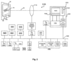
- Mobile computer 100 can include one or more processors 1060 communicatively coupled to system bus 1500.
- processors 1060 may illustratively be or include a central processing unit (CPU), a complex programmable logic device (CPLD), an application-specific integrated circuit (ASIC), a field programmable gate array (FPGA), or any type of circuit capable of processing logic operations, in accordance with various embodiments.
- CPU central processing unit
- CPLD complex programmable logic device
- ASIC application-specific integrated circuit
- FPGA field programmable gate array
- the mobile computer 100 can further comprise one or more communication interfaces 1604, 1608 for providing communications with external devices.
- Communication interfaces 1604, 1608 can include one or more wired interfaces (e.g., Ethernet (IEEE 802.3), USB, RS/485, etc .) and one or more wireless interfaces (e.g., interfaces configured to support at least one protocol of the IEEE 802.11/802.15/802.16 protocol family, at least one protocol of the HSPA/GSM/GPRS/EDGE protocol family, TDMA protocol, UMTS protocol, LTE protocol, and/or at least one protocol of the CDMA/1xEV-DO protocol family).
- wired interfaces e.g., Ethernet (IEEE 802.3), USB, RS/485, etc .
- wireless interfaces e.g., interfaces configured to support at least one protocol of the IEEE 802.11/802.15/802.16 protocol family, at least one protocol of the HSPA/GSM/GPRS/EDGE protocol family, TDMA protocol, UMTS protocol, LTE protocol,
- mobile computer 100 can further include a direct memory access unit (DMA) 1070 providing direct communications of one or more devices communicatively coupled to system bus 1500 with RAM 1080.
- DMA direct memory access unit
- mobile computer 100 can employ a system bus providing for bus arbitration mechanism (e.g., a PCI bus) thus eliminating the need for a central DMA controller.
- bus arbitration mechanism e.g., a PCI bus
- Other embodiments of the system bus architecture and/or direct memory access components providing for efficient data transfer between one or more devices communicatively coupled to system bus 1500 and RAM 1080 can be provided.
- mobile computer 100 can include a built-in imaging device 1040 configured to acquire two-dimensional monochrome and/or color images.
- Imaging device 1040 can comprise an image sensor 1032 including a multiple pixel image sensor 1033 array having pixels arranged in rows and columns, associated column circuitry 1034, and row circuitry 1035.
- the image sensor 1033 can be provided by a charge-coupled device (CCD) image sensor.
- the image sensor can be provided by a complementary metal-oxide semiconductor (CMOS) image sensor.
- CMOS complementary metal-oxide semiconductor
- Associated with the image sensor 1032 can be amplifier circuitry 1036, and an A/D converter 1037 which converts image information in the form of analog signals read out of image sensor 1033 into image information in the form of digital signals.
- the A/D converter 1037 can be provided by an A/D array.
- Image sensor 1032 can also have an associated timing and control circuit 1038 for use in controlling e.g ., the exposure period of image sensor 1032, gain applied to the amplifier circuitry 1036.
- the circuit components 1032, 1036, 1037, and 1038 can be packaged into a common imaging device 1040.
- Mobile computer 100 can include interface circuit 1026 for coupling image sensor timing and control circuit 1038 to system bus 1500.
- Mobile computer 100 can be configured to read out analog signals representative of light incident on one or more pixels.
- the read out analog signals can be amplified by the analog signal amplifier 1036.
- the analog signals can then be fed to the input of the ADC 1037.
- the resulting digital values representative of the analog signals can be stored in a system memory such as RAM 1080.
- Image frame data stored in RAM 1080 can be in the form of multibit pixel values, with each multibit pixel value representing light incident on a pixel of image sensor 1033.
- DMA unit 1070 can route image information read out from image sensor 1032 to RAM 1080.
- processor 1060 can be programmed to read out image data stored in memory 1080 and subject such image data to various image processing algorithms.
- the mobile computer 100 can include a variable focus imaging lens 1110 for use in focusing an image of a decodable indicia located within a field of view 140 on a substrate 50 onto image sensor 1033. Imaging light rays can be transmitted about imaging axis 25. Variable focus imaging lens 1110 can be adapted to be capable of multiple best focus distances and multiple focal lengths. Variable focus imaging lens 1110 can be operative to provide a new best focus distance and/or focal length within a fraction of a frame time in response to an applied input control signal being applied to the variable focus imaging lens 1110. In one embodiment, the variable focus imaging lens 1110 can be provided by a deformable imaging lens, e.g., a deformable fluid lens or gel lens.
- a deformable imaging lens e.g., a deformable fluid lens or gel lens.
- variable focus imaging lens 1110 can be provided by a non-deformable fluid lens, e.g., an electrowetting liquid lens wherein the surface tension of one or more volumes of lens liquid changes in response to a signal being applied to the lens, or a liquid crystal type lens wherein indices of refraction of one or more volumes of lens fluid change in response to a signal being applied to the lens.
- a non-deformable fluid lens e.g., an electrowetting liquid lens wherein the surface tension of one or more volumes of lens liquid changes in response to a signal being applied to the lens
- a liquid crystal type lens wherein indices of refraction of one or more volumes of lens fluid change in response to a signal being applied to the lens.
- Mobile computer 100 can further comprise a battery 356.
- Mobile computer 100 can further comprise a GPS receiver 380 communicatively coupled to system bus 1500 via interface 382.
- the mobile computer 100 can further comprise at least one connector 390 configured to receive a subscriber identity module (SIM) card, also communicatively coupled to system bus 1500.
- SIM subscriber identity module
- the mobile computer 100 can further comprise an embedded encoded information reading (EIR) device 333 communicatively coupled to system bus 1500 via interface 335.
- EIR device 333 can be provided, for example, by a laser scanning device, an RFID reading device, an NFC reading device, or a magnetic card reading device.
- the EIR device can be configured to output raw message data containing an encoded message and/or output decoded message data corresponding to the encoded message.
- “message” is intended to denote a byte sequence or a character string comprising alphanumeric and/or non-alphanumeric characters.
- An encoded message can be used to convey information, such as identification of the source and the model of an item, for example, in an EPC code.
- the RFID reading device can be compliant with EPC TM Class-1 Generation-2 UHF RFID Protocol for Communications at 860 MHz - 960 MHz by EPCglobal, commonly known as the "Gen 2" standard, which defines physical and logical requirements for a passive-backscatter, Interrogator-talks-first (ITF) RFID system operating in the 860 MHz - 960 MHz frequency range.
- EPC TM Class-1 Generation-2 UHF RFID Protocol for Communications at 860 MHz - 960 MHz by EPCglobal commonly known as the "Gen 2" standard, which defines physical and logical requirements for a passive-backscatter, Interrogator-talks-first (ITF) RFID system operating in the 860 MHz - 960 MHz frequency range.
- the NFC reading device of the EIR terminal can be compliant with NFC Digital Protocol Technical Specification DIGITAL 1.0 NFCForum-TS-DigitalProtocol-1.0 of 2010-11-17 by NFC Forum TM .
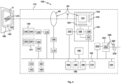
- mobile computer 100 can transmit, via a wired or wireless communication interface and one or more communication networks, one or more decodable indicia images and/or one or more messages corresponding to successfully decoded decodable indicia to an external computer.
- mobile computer 100a-100z can access the external computer 171 over one or more local and/or wide area networks 110a-110z.
- Mobile computer 100a-100z can connect to one or more networks 110a-110z, e.g., via a wireless access point 135.
- at least one of networks 110a-110z can be provided by an IEEE 802.11x-compliant wireless network.
- At least one of networks 110a-110z can be provided by an Ethernet network. In another embodiment, at least one of networks 110a-110z can be provided by a local area network (LAN). In another embodiment, at least one of networks 110a-110z can be provided by a wide area network (WAN). While different networks are designated herein, it is recognized that a single network as seen from the network layer of the OSI model can comprise a plurality of lower layer networks, i.e., what can be regarded as a single Internet Protocol (IP) network, can include a plurality of different physical networks.
- IP Internet Protocol
- the communications between mobile computer 100 and external computer 171 can comprise a series of requests and responses transmitted over one or more TCP connections, although a person skilled in the art would appreciate the fact that using other transport and application level protocols is within the scope of this disclosure.
- at least one data frame transmitted by mobile computer 100 to external computer 171 can comprise one or more images of decodable indicia and/or one or more messages corresponding to decodable indicia successfully decoded by mobile computer 100.
- external computer 171 can, in some embodiments, retrieve information corresponding to the decoded message from a database and transmit at least part of the retrieved information to mobile computer 100.
- the decoded message can comprise a retail item identifier, and the information retrieved from the database and transmitted to the mobile computer 100 can comprise the retail item price and/or other characteristics.
- the decoded message can comprise a medical patient identifier, and the information retrieved from the database and transmitted to the mobile computer 100 can comprise patient treatment information.
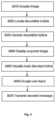
- One embodiment of a method of processing multiple decodable indicia by mobile computer is schematically illustrated by the block diagram of FIG. 4 .
- the method can be implemented using one or more processors of one or more computers.
- the method can be implemented using one or more processors of mobile computer 100.
- the method can be implemented using one or more processors of two or more computers.
- mobile computer 100 can acquire an image of one or more objects bearing one or more decodable indicia within the field of view the mobile computer's imaging device.
- mobile computer 100 can locate one or more decodable indicia within the acquired image.
- mobile computer 100 can decode at least one decodable indicium of the decodable indicia located within the acquired image.
- mobile computer 100 can display the acquired image on display 1304.
- mobile computer 100 can visually mark the one or more successfully decoded decodable indicia within the displayed image.
- mobile computer 100 can highlight the successfully decoded decodable indicia.
- mobile computer 100 can draw a bounding box around the successfully decoded decodable indicia.
- a circular dot or some other visual marker can be placed in or around the center of the successfully decoded decodable indicia.
- mobile computer 100 can accept the user input selecting at least one decodable indicia of the displayed one or more decodable indicia.
- selecting one or more decodable indicia can be performed via touch screen by the user's tapping the screen areas containing the images of one or more decodable indicia.
- the user's repetitive tapping the screen area containing a decodable indicia image can toggle on or off the inclusion of the indicia and/or a decoded message corresponding to the indicia into the sequence of messages to be transmitted to an external computer.
- mobile computer 100 can transmit to an external computer at least one decoded message corresponding to the at least one decodable indicia, and the method can terminate.
- mobile computer 100 can accept user input indicating which indicia and in which order need to be used by one or more applications. Responsive to accepting the user input selecting two or more decodable indicia, the mobile computer can transmit to an external computer, in the order indicated by the user, the decoded messages corresponding to the selected indicia, and the method can terminate.
- a computer-readable storage medium comprising executable instructions capable of configuring one or more processors for implementing the above described method.
- an imaging apparatus 1000 can be operative to capture a frame of image data representing a scene having a plurality of decodable indicia and display image data corresponding the decodable indicia.
- the imaging apparatus 1000 can be operative so that responsively to a user input control decoded message data of a selected decodable indicia is selectively output.
- the selective output can be, e.g., to a different functional block of a current program performing the display, and/or a different program, the image apparatus and/or to one or more external processor equipped apparatus for use in one or more program therein.
- imaging apparatus 1000 can include an imaging assembly 400 for use in capturing a frame of image data representing a scene within a field of view 600 of imaging assembly 400. Because apparatus 1000 includes imaging assembly 400, field of view 600 can also be regarded as a field of view of apparatus 1000.
- the scene within field of view 600 as indicated in the example of FIG. 5 can include a plurality of decodable indicia, e.g ., bar codes 202, 204, 206. Decodable indicia can also include text including OCR characters.
- an unwanted decoded message data can be output to a designated output destination.. For example, referring to the scene of FIG.
- an operator may wish that a decoded message decoded by processing a representation of bar code 206 be output; however, a decoded message of bar code 204 may instead be inadvertently output, e.g ., if apparatus 1000 is programmed to decode and output a center-most decodable indicia.
- the imaging apparatus 1000 can be operative so that responsively to a user input control decoded message data of a selected decodable indicia, e.g., a selected one or more of decodable indicia provided by bar code 202, bar code 204, and bar code 206 is selectively output.
- imaging apparatus 1000 can be operative so that imaging apparatus 1000 is restricted from outputting decoded message data of a certain indicia unless the operator inputs a control to apparatus 1000 to output decoded message data of the certain decodable indicia.
- Imaging apparatus 1000 can include an image sensor 1032 comprising a multiple pixel image sensor array 1033 having pixels arranged in rows and columns of pixels, associated column circuitry 1034 and row circuitry 1035. Associated with the image sensor 1032 can be amplifier circuitry 1036, and an analog to digital converter 1037 which converts image information in the form of analog signals read out of image sensor array 1033 into image information in the form of digital signals. Image sensor 1032 can also have an associated timing and control circuit 1038 for use in controlling e.g ., the exposure period of image sensor 1032, gain applied to the amplifier 1036.
- imaging device 1040 e.g., a common image sensor integrated circuit.
- imaging device 1040 can be provided by an MT9V022 image sensor integrated circuit available from Micron Technology, Inc.
- imaging device 1040 can incorporate a Bayer pattern filter.
- CPU 1060 prior to subjecting a frame to further processing can interpolate pixel values intermediate of green pixel values for development of a monochrome frame of image data.
- apparatus 1000 image signals can be read out of image sensor 1032, converted and stored into a system memory such as RAM 1080.
- a memory 1085 of apparatus 1000 can include RAM 1080, a nonvolatile memory such as EPROM 1082 and a storage memory device 1084 such as may be provided by a flash memory or a hard drive memory.
- apparatus 1000 can include CPU 1060 which can be adapted to read out image data stored in memory 1080 and subject such image data to various image processing algorithms.
- Apparatus 1000 can include a direct memory access unit (DMA) 1070 for routing image information read out from image sensor 1032 that has been subject to conversion to RAM 1080.
- DMA direct memory access unit
- apparatus 1000 can employ a system bus providing for bus arbitration mechanism (e.g., a PCI bus) thus eliminating the need for a central DMA controller.
- bus arbitration mechanism e.g., a PCI bus
- system bus architecture and/or direct memory access components providing for efficient data transfer between the image sensor 1032 and RAM 1080 are within the scope and the spirit of the invention.
- lens assembly 200 can be adapted for focusing an image of a decodable indicia 15 located within a field of view 1240 on a substrate 1250 onto image sensor array 1033. Imaging light rays can be transmitted about imaging axis 25. Lens assembly 200, in one embodiment, can be adapted to be capable of multiple focal lengths and multiple best focus distances.
- An imaging assembly 400 of apparatus 1000 can include lens assembly 200 and image sensor array 1033.
- Apparatus 1000 can also include an illumination pattern light source bank 1204 and associated light shaping optics 1205 for generating an illumination pattern 1260 substantially corresponding to a field of view 1240 of apparatus 1000.
- the combination of bank 1204 and optics 1205 can be regarded as an illumination pattern generator 1206.
- Apparatus 1000 can also include an aiming pattern light source bank 1208 and associated light shaping optics 1209 for generating an aiming pattern 1270 on substrate 1250.
- the combination of bank 1208 and optics 1209 can be regarded as an aiming pattern generator 1210.
- apparatus 1000 can be oriented by an operator with respect to a substrate 1250 bearing decodable indicia 15 in such manner that aiming pattern 1270 is projected on a decodable indicia 15. In the example of FIG.
- decodable indicia 15 is provided by a 1D bar code symbol. Decodable indicia 15 could also be provided e.g ., by a 2D bar code symbol or decodable text such as optical character recognition (OCR) characters.
- decodable indicia 202 is provided by a UPC bar code symbol
- decodable indicia 204 is provided by a QR code symbol
- decodable indicia 206 is provided by a code 128 symbol.
- Each of illumination pattern light source bank 1204 and aiming pattern light source bank 1208 can include one or more light sources.
- Lens assembly 200 can be controlled with use of electrical power input unit 1055 which provides energy for changing a plane of optimal focus of lens assembly 200.
- an electrical power input unit 1055 can operate as a controlled voltage source, and in another embodiment, as a controlled current source.
- Illumination pattern light source bank 1204 can be controlled with use of illumination pattern light source control circuit 1220.
- Aiming pattern light source bank 1208 can be controlled with use of aiming pattern light source bank control circuit 1222.
- Electrical power input unit 1055 can apply signals for changing optical characteristics of lens assembly 200, e.g., for changing a focal length and/or a best focus distance of (a plane of optimum focus of) lens assembly 200.
- Illumination pattern light source bank control circuit 1220 can send signals to illumination pattern light source bank 1204, e.g., for changing a level of illumination output by illumination pattern light source bank 1204.
- Aiming pattern light source bank control circuit 1222 can send signals to aiming pattern light source bank 1208, e.g., for changing a lumen of illumination output by aiming pattern light source bank 1208.
- imaging apparatus 1000 can be devoid of elements that project an illumination pattern.
- Apparatus 1000 can also include a number of peripheral devices including trigger R1408 which may be used to make active a trigger signal for activating frame readout and capture and/or certain decoding processes and/or other processes. Apparatus 1000 can be adapted so that manual actuation of trigger R1406 activates a trigger signal and initiates a decode attempt.
- trigger R1408 is provided by a virtual trigger that is displayed on display 1420.
- a hardware actuator e.g ., of keyboard 1406 can also be configured as a trigger.
- Apparatus 1000 can be operative so that in response to activation of a trigger signal, a succession of frames can be read out and captured by way of read out of image information from image sensor array 1033 (typically in the form of analog signals) and then storage of the image information after conversion into memory 1080 (which can buffer one or more of the succession of frames at a given time).
- CPU 1060 can be operative to subject one or more of the succession of frames to a decode attempt.
- CPU 1060 can process image data of a frame corresponding to a line of pixel positions (e.g., a row, a column, or a diagonal set of pixel positions) to determine a spatial pattern of dark and light cells and can convert each light and dark cell pattern determined into a character or character string via table lookup.
- a line of pixel positions e.g., a row, a column, or a diagonal set of pixel positions
- a decode attempt can comprise the steps of locating a finder pattern using a feature detection algorithm, locating matrix lines intersecting the finder pattern according to a predetermined relationship with the finder pattern, determining a pattern of dark and light cells along the matrix lines, and converting each light pattern into a character or character string via table lookup.
- CPU 1060 can run one or more program 1800 as set forth herein when decoding decodable indicia.
- a trigger signal can be made active by entering a selective decoded message data output mode in which apparatus 1000 can selectively output candidate decoded message data responsively to an operator input control to select for output decoded message data of a certain decodable indicia.
- apparatus 1000 can be operative to continually attempt to decode frames of a succession of frames and responsively to an operator input control can output decoded message data of a subset e.g ., one, frames successfully decoded during operation in the mode.
- Apparatus 1000 can include various interface circuits for coupling various of the peripheral devices to system address/data bus (system bus) 1500, for communication with CPU 1060 also coupled to system bus 1500.
- Apparatus 1000 can include interface circuit 1028 for coupling image sensor timing and control circuit 1038 to system bus 1500, interface circuit 1118 for coupling electrical power input unit 1055 to system bus 1500, interface circuit 1218 for coupling illumination light source bank control circuit 1220 to system bus 1500, interface circuit 1224 for coupling aiming light source bank control circuit 1222 to system bus 1500, and interface circuit 1404 for coupling keyboard 1406 to system bus 1500.
- Apparatus 1000 can also include a display 1420 coupled to system bus 1500 and in communication with CPU 1060, via interface 1418.
- apparatus 1000 can include a network communication interface 1426 couple to system bus 1500.
- Network communication interface 1426 can be e.g., one or more of an IEEE 802.11 interface a Bluetooth interface or a cellular radio interface.
- server 2000, server 3000 can include CPU 1060 memory 1085 bus 1500 and communication interface 1426 components corresponding to those described in connection with apparatus 1000.
- apparatus 1000, server 2000, and server 3000 can be in communication with one another via, e.g., the TCP/UDP or TCP/IP suite of network communication protocols.
- Display 1420 in one embodiment can be a touch screen display having a touch panel associated to display apparatus.
- a succession of frames of image data that can be captured and subject to the described processing can be full frames (including pixel values corresponding to the maximum number of pixels subject to readout during a course of operation of apparatus 1000).
- a maximum number of pixels is each pixel of image sensor array 1033.
- a succession of frames of image data that can be captured and subject to the described processing can also be "windowed frames" comprising pixel values corresponding to less than a maximum number of pixels subject to readout during a course of operation of apparatus 1000.
- a succession of frames of image data that can be captured and subject to the described processing can also comprise a combination of full frames and windowed frames.
- a full frame can be captured by selectively addressing for readout pixels of image sensor 1032 corresponding to the full frame.
- a windowed frame can be captured by selectively addressing for readout pixels of image sensor 1032 corresponding to the windowed frame.
- apparatus 1000 can include a second imaging device 2040 (e.g., a second image sensor integrated circuit) disposed in combination with a second imaging lens assembly 2200 for capture of image data in the manner set forth in reference to imaging device 1040.
- Second imaging device 2040 can include an image sensor array 2033 and the remaining elements set forth with reference to imaging device 1040.
- a second imaging assembly 2400 of apparatus 1000 can include an image sensor assembly 2033 and lens assembly 2200.
- Second imaging device 2040 can be in communication with system bus 1500 via interface 2028.
- Second imaging device 2040 can be aperture for use in capturing frames of image data in the manner of imaging device 1040.
- Received light rays received by imaging assembly 400 can be received about imaging axis 25.
- Imaging axis 25 can extend downwardly from apparatus 1000. Imaging axis 2025 can extend upwardly from apparatus 1000. Indicated by the side view reference view of FIG. 5 imaging axis 25 can extend vertically downward and can be perpendicular relative to a display plane P420 on which display 1420 extends. Imaging axis 2025 can extend vertically downward and can be perpendicular relative to display plane P1420 on which display 1420 extends. Apparatus 1000 can capture frames of image data at a rate known as a frame rate. A typical frame rate is 60 frames per second (FPS) which translates to a frame time (frame period) of 16.6 ms. Another typical frame rate is 30 frames per second (FPS) which translates to a frame time (frame period) of 33.3 ms per frame.
- FPS frames per second
- an electrical power input applied by electrical power input unit 1055 for establishing a desired lens setting of lens assembly 200 can be responsive, e.g., to a sensed condition or an operator input command.
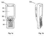
- FIG. 5 A physical form view of apparatus 1000 in one embodiment is shown in FIG. 5 .
- Display 1420 and keyboard 1406 can be disposed on a common side of a hand held housing 1014 as shown in FIG. 5 .
- Display 1420 and keyboard 1406 in combination can be regarded as a user interface of apparatus 1000.
- Display 1420 can be a touch screen display in one embodiment.
- a user interface of apparatus 1000 can also be provided by configuring apparatus 1000 to be operative to be reprogrammed by decoding of programming bar code symbols.
- Apparatus 1000 can include a hand held housing 1014 that supports imaging assembly 400 and imaging assembly 2400 that can be disposed in ( e.g., entirely or partially) in hand held housing 1014.
- a computer program product 1700 comprising a computer readable storage medium 1702 storing one or more program 1800, the one or more program 1800 comprising program code logic for facilitating selective decoded message data.
- One or more program 1800 can include computer executable instructions executable by a processor e.g ., CPU 1060 of apparatus 1000.
- CPU 1060 of apparatus 1000 can be operative to run the computer executable one or more program 1800 having the functions that are indicated in the flow diagram of FIG. 8 .
- one or more program 1800 can display image data corresponding to a plurality of decodable indicia in a field of view of apparatus 1000 e.g., a field of view 600 as set forth in FIG. 5 .
- one or more program 1800 can output to an output destination decoded message data responsively to an operator input control to output decoded message data of a selected decodable indicia.
- one or more program 1800 in the performance of block 1802 can send for display on display1420 image data of a frame of image data captured by imaging apparatus 1000.
- displayed image data displayed on display 1420 can include representations R202, R204, R206 of decodable indicia e.g. , decodable indicia 202, 204, 206 shown as being provided by bar code symbols within field of view 600.
- the frame of image data can be a contemporaneously captured frame captured using apparatus 1000.
- the image data that is displayed can be formatted by highlighting representations of decodable indicia that can be decoded using currently captured image data.
- One or more program 1800 for determining whether decodable indicia can be decoded using currently captured image data can attempt to decode the decodable indicia using currently captured image data, e.g., currently stored e.g., buffered image data for processing, e.g., as may be buffered in RAM 1080.
- One or more program 1800 can determine that a decodable indicia is decodable by successfully decoding the indicia.
- one or more program 1800 can determine that a decodable indicia is decodable by successfully locating the decodable indicia in a currently captured frame of image data.
- a displayed highlight that highlights a representation of a decodable indicia can be a border, e.g. , border R302, R304, R306.
- a displayed representation of decodable indicia that is determined to be decodable using currently captured image data is displayed using a selective flashing display (image data representing a scene can be displayed with only areas representing decodable indicia displayed in a flashing display).
- a highlighting can include decoded messages R402, R404, R406 of a decodable indicia being represented by displayed image data. While various highlighting schemes are possible, it will be understood that no highlighting is necessary.
- one or more program 1800 provisions apparatus 1000 so that an operator can select a certain decodable indicia without any highlighting of the decodable indicia ( e.g., mere display of a representation of the decodable indicia without any highlighting).
- a method comprising displaying, using a processor, image data corresponding to one or more decodable indicia in a field of view of an imaging apparatus, and outputting, using the processor, decoded message data of a selected decoded indicia responsively to an operator input control to output decoded message data of a selected decodable indicia of the one or more decodable indicia, wherein an operator input control to output decoded message data of a selected decodable indicia comprises a touching of a location of a display that displays a representation of the selected decodable indicia selected by the touching.
- the decoded message data of the selected decodable indicia can be determined, e.g ., prior to or after the time of a selection of the selected decodable indicia.
- a method comprising displaying, using a processor, image data corresponding to one or more decodable indicia in a field of view of an imaging apparatus, wherein the one or more decodable indicia has been subject to decoding processing at a time of the displaying, and outputting, using the processor, decoded message data of a selected decoded indicia responsively to an operator input control to output decoded message data of a selected decodable indicia of the one or more decodable indicia.
- the decoding processing comprises attempting to decode.
- the decoding processing includes completing decoding by determining a decoded message.
- the decoding processing comprises determining a location of a decodable indicia (typically a first step in a decode attempt).
- determining a location of a decodable indicia with no further decoding processing steps prior to display of image data of frame on display 1420 one or more program 1800 is able to monitor an output of display interface 1418 of display 1420 (where provided by a touch screen display) to determine whether an area of a display corresponding to a location of a displayed decodable indicia representation has been touched.
- one or more program 1800 can selectively output decoded message data responsively to a use input control to selectively output decoded message data.
- the selective output can be to an output destination.
- the output destination can be a different function block of one or more program 1800 running on CPU 1060.
- the output destination can be to a program running on CPU 1060 other than one or more program 1800.
- the output destination can be an external processor equipped apparatus, e.g ., server 2000 or server 3000 for use by one or more program running thereon.
- CPU 1060 can communicate with a network communication interface 1426.
- a communication between apparatus 1000 and server 2000 or server 3000 can employ a suitable protocol running over the TCP/UDP transport layer, e.g., HTTP or XML.
- one or more program 1800 can monitor for an occurrence of an operator input control to transmit decoded message data of a selected decodable indicia.
- monitoring of which one or more program 1800 can detect for can include, e.g., tactile monitoring (e.g., a touching of display 1420 where provided by a touch screen), acoustical monitoring, ( e.g., where an operator inputs a voice command), an image based monitoring, ( e.g., one or more program 1800 determines where an operator is looking based on processing of image data captured using an imaging assembly).
- one or more program 1800 processes a single frame of image data, e.g., to display image data of the frame on display 1420, to attempt to decode the frame of image data, to determine whether the frame of image data is decodable using currently captured image data, to highlight representations of decodable indicia determined to be decodable using currently captured image data.
- one or more program 1800 can display a still frame in the performance of block 1802.
- one or more program 1800 at block 1802 processes a plurality of frames of image data, e.g., to display image data of frames of a succession of frames of image data on display 1420 (a rendering of a motion image), to attempt to decode frames of a succession of frames of image data, to determine whether frames of a succession of frames of image data are decodable using currently captured image data, to highlight representations of decodable indicia in frames of a succession of frames determined to be decodable using currently captured image data.
- one or more program 1800 can obtain frames of a sequence of frames output by a camera library running on CPU 1060.
- a program of one or more program can control imaging device 1040 for image capture as set forth herein.
- One or more program 1800 can attempt to decode each incoming frame with a timeout (quits the decoding if decoding is not complete within a specified time). If one or more program 1800 successfully decodes a decodable indicia (or otherwise determines it to be decodable using currently captured image data), one or more program 1800 can highlight the representation of the decodable indicia in the frame image data.
- one or more program 1800 When one or more program 1800 decodes a decodable indicia it can determine coordinates of the decodable indicia representations and associate that coordinate data to a decoded message. One or more program 1800 can provide highlights to a decodable indicia representation by appropriately changing values of pixels in locations proximate the decodable indicia representation. If one or more or more program 1800 is not successful in decoding a frame of image data of a succession of frames, it may nevertheless send image data of the frame to display 1420. A succession of displayed frames will appear to have highlights that track a location of a decodable indicia representation over a succession of frames provided a suitable percentage of the frames have decodable indicia representations that are highlighted.
- one or more program 1800 can display a prior frame on display 1420 with highlighted decodable indicia representations after it has decoded it after it has displayed a subsequent frame. Such "out of sequence" display however is unlikely to be perceived by an operator if decoding and highlighting is performed quickly enough.
- apparatus 1000 can be operative to continually attempt to decode frames of a succession of frames and responsively to an operator input control can output decoded message data of a subset (e.g., one, a select few) of decodable indicia represented frames successfully decoded during operation in the mode.
- a selective decodable message data output mode allows an operator to select (filter) which decoded message data out of a plurality of candidate decoded message data should be output to an output destination.
- a selective decodable message data output mode can be made active by actuation of virtual mode button R1407 or virtual trigger button R1406 (in one specific embodiment the selective decodable message data output mode is provided as a special configuration wherein the mode is activated rather than standard decoding when trigger button R1406 is activated).
- activation of the mode results in one or more program 1800 at block 1802 displaying image data of frames of a succession of frames (a motion image) on display 1420 with highlighting of decodable indicia representation of decodable indicia that can be decoded using currently captured image data.
- one or more program can selectively output decoded message data of the decodable indicia.
- Virtual actuators R1406 and R1407 are shown in dashed view in FIG. 5 since one or more program 1800 can be operative so that virtual actuators R1406 and R1407 are not displayed at a same time the remaining shown as displayed elements set forth in FIG. 5 .
- apparatus 1000 can be used to facilitate selection of decodable message data of, for example one out of a plurality of decodable indicia, each of the plurality of decodable indicia 202, 204, 206 having a corresponding displayed representation R202, R204, R206.
- apparatus 1000 in accordance with the functions of one or program 1800 set forth in FIG. 8 need not be used to allow selection of one or more out of a plurality of decodable indicia, but rather may be used to select (or not select) decoded message data of a single decodable indicia for selective output.
- one or more program 1800 can be operative so that apparatus 1000 is restricted from outputting to a designated output destination decoded message data unless the decoded message data is of an operator selected decodable indicia designated as being selected by a predetermined operator input control.
- apparatus 1000 can be used to allow an operator to select between first and second decodable indicia.
- Apparatus 1000 can display representations of the first and second indicia simultaneously (if both are in field of view 600 simultaneously) or sequentially (if apparatus 1000 is moved between locations so that the first and second decodable indicia are in a field of view 600 sequentially).
- apparatus 1000 may sequentially decode a plurality of decodable indicia so that a plurality of the decoded massage data, e.g ., first decoded message data, second decoded message data, are candidates for output.
- a plurality of the decoded massage data e.g ., first decoded message data, second decoded message data
- candidate decoded message data that is available for selective output can be of decoded message data determined by decoding spatially separated decodable indicia (of a common frame) or sequentially separated decodable indicia (represented in frames captured at different times).
- One or more program 1800 at block 1802 can display highlights of a decodable indicia. Such highlights are useful in all use cases including where apparatus 1000 is used to allow an operator to select or not select (pass over) decodable indicia of a single decodable indicia representation. For example, where the highlight is a display of a decoded message, the display allows the operator to discern whether the data is the data that the operator wishes to output.
- one or more program 1800 can message resources in providing a highlight for display on display 1420.
- the resources can be e.g., one or more database stored locally on apparatus 1000 or externally e.g., on local server ( e.g., a store server if in a retail store environment), or a remote server 3000.
- the database is a price lookup table.
- the database is a lookup table correlating product images to decoded messages.
- One example is the GOOGLE SHOPPER API which on messaging with a decoded message can return a product image.
- One or more program 1800 at block 1802 can message a resource and in one embodiment can message an external resource, e.g ., a database of server 2000 or server 3000.
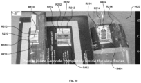
- FIG. 9 illustrates a returned product image displayed as a highlight R608.
- One or more program 1800 also displays a highlight in the form of a displayed price R708.
- One or more program 1800 at block 1802 can determine price data by messaging a price lookup table stored locally on apparatus 1000 or externally e.g ., on server 2000 or server 3000.
- the decoded message data can also include for example (c) data determined by messaging a resource using a decoded message, e.g ., a product price, a product image.
- Decoded message data that is output at block 1804 can include any combination of the (a) (b) and (c) types of data, e.g., can include data of all of the types (a) (b) and (c) or just one or two of the types, e.g ., just type (a) just type (b), just type (c).
- One or more program 1800 can provision apparatus 1000 so that an operator can select a decodable indicia by touching a displayed highlight of a decodable indicia in addition to or in place of a representation of a decodable indicia.
- One or more program 1800 can provision apparatus 1000 so that a touch sensitivity of display 1420 is provided with appropriately configured active periods so that, an e.g., an operator who touches an area of a displayed highlight within a timeout period after it ceases to be displayed nevertheless designates a selection of a decodable indicia.
- the one or more program 1800 provisions apparatus 1000 to restrict to decoded message data of a decodable indicia from being output to an output destination unless an operator inputs an operator control input to apparatus 1000 to output decoded message data of a selected decodable indicia, e.g., the decodable indicia 202, 204, 206 of representations R202, R204, R206 which may be selected by a method set forth herein.
- apparatus 1000 is configured so that one or more program 1800 so restricts apparatus 1000 from outputting decoded message data other than decoded message data of selected decodable indicia during each possible operating mode of apparatus 1000.
- apparatus 1000 is configured so that one or more program 1800 so restricts apparatus 1000 from outputting decoded message data other than decoded message data of selected decodable indicia during only select operating modes of apparatus 1000 (and not each possible operating mode).
- One or more program 1800 can be stored on a computer readable storage medium provided by one or more memory device of a memory of an external CPU-equipped apparatus (e.g., a server, an external apparatus configured in the manner of apparatus 1000), and downloaded to apparatus 1000.
- One or more program 1800 can be stored on a computer readable storage medium provided by one or more memory device of a memory 1085 of apparatus 1000.
- one or more program 1800 can be stored on a computer readable storage medium that is physically transportable, e.g ., compact disk, floppy disk, thumb drive.
Landscapes
- Engineering & Computer Science (AREA)
- Physics & Mathematics (AREA)
- Theoretical Computer Science (AREA)
- General Physics & Mathematics (AREA)
- Electromagnetism (AREA)
- General Engineering & Computer Science (AREA)
- Toxicology (AREA)
- Health & Medical Sciences (AREA)
- Human Computer Interaction (AREA)
- General Health & Medical Sciences (AREA)
- Computer Hardware Design (AREA)
- Artificial Intelligence (AREA)
- Computer Vision & Pattern Recognition (AREA)
- User Interface Of Digital Computer (AREA)
- Character Input (AREA)
- Telephone Function (AREA)
- Character Discrimination (AREA)
- Studio Devices (AREA)
- Image Input (AREA)
- Image Processing (AREA)
Applications Claiming Priority (7)
| Application Number | Priority Date | Filing Date | Title |
|---|---|---|---|
| US201261726747P | 2012-11-15 | 2012-11-15 | |
| US201261737552P | 2012-12-14 | 2012-12-14 | |
| US13/743,477 US9064168B2 (en) | 2012-12-14 | 2013-01-17 | Selective output of decoded message data |
| US13/748,926 US9208367B2 (en) | 2012-11-15 | 2013-01-24 | Mobile computer configured to read multiple decodable indicia |
| EP24156878.1A EP4345681A3 (de) | 2012-11-15 | 2013-11-08 | Mobiler computer mit konfiguration zum lesen mehrerer decodierbarer indizien |
| EP13192219.7A EP2733641B1 (de) | 2012-11-15 | 2013-11-08 | Mobiler Computer, der zum Lesen mehrerer dekodierbarer Zeichen konfiguriert ist |
| EP21160116.6A EP3866051B8 (de) | 2012-11-15 | 2013-11-08 | Zum lesen mehrerer decodierbarer zeichen konfigurierter, mobiler computer |
Related Parent Applications (3)
| Application Number | Title | Priority Date | Filing Date |
|---|---|---|---|
| EP13192219.7A Division EP2733641B1 (de) | 2012-11-15 | 2013-11-08 | Mobiler Computer, der zum Lesen mehrerer dekodierbarer Zeichen konfiguriert ist |
| EP24156878.1A Division EP4345681A3 (de) | 2012-11-15 | 2013-11-08 | Mobiler computer mit konfiguration zum lesen mehrerer decodierbarer indizien |
| EP21160116.6A Division EP3866051B8 (de) | 2012-11-15 | 2013-11-08 | Zum lesen mehrerer decodierbarer zeichen konfigurierter, mobiler computer |
Publications (2)
| Publication Number | Publication Date |
|---|---|
| EP4524810A2 true EP4524810A2 (de) | 2025-03-19 |
| EP4524810A3 EP4524810A3 (de) | 2025-05-21 |
Family
ID=50941089
Family Applications (3)
| Application Number | Title | Priority Date | Filing Date |
|---|---|---|---|
| EP25155125.5A Pending EP4524810A3 (de) | 2012-11-15 | 2013-11-08 | Mobiler computer mit konfiguration zum lesen mehrerer decodierbarer indizien |
| EP25155124.8A Pending EP4557162A1 (de) | 2012-11-15 | 2013-11-08 | Mobiler computer mit konfiguration zum lesen mehrerer decodierbarer indizien |
| EP24156878.1A Pending EP4345681A3 (de) | 2012-11-15 | 2013-11-08 | Mobiler computer mit konfiguration zum lesen mehrerer decodierbarer indizien |
Family Applications After (2)
| Application Number | Title | Priority Date | Filing Date |
|---|---|---|---|
| EP25155124.8A Pending EP4557162A1 (de) | 2012-11-15 | 2013-11-08 | Mobiler computer mit konfiguration zum lesen mehrerer decodierbarer indizien |
| EP24156878.1A Pending EP4345681A3 (de) | 2012-11-15 | 2013-11-08 | Mobiler computer mit konfiguration zum lesen mehrerer decodierbarer indizien |
Country Status (6)
| Country | Link |
|---|---|
| EP (3) | EP4524810A3 (de) |
| JP (6) | JP6339349B2 (de) |
| CN (1) | CN204155287U (de) |
| DE (4) | DE202013012943U1 (de) |
| ES (1) | ES2972819T3 (de) |
| PL (1) | PL3866051T3 (de) |
Families Citing this family (14)
| Publication number | Priority date | Publication date | Assignee | Title |
|---|---|---|---|---|
| EP2733641B1 (de) | 2012-11-15 | 2021-08-04 | Hand Held Products, Inc. doing business as Honeywell Scanning & Mobility | Mobiler Computer, der zum Lesen mehrerer dekodierbarer Zeichen konfiguriert ist |
| JP2016110226A (ja) * | 2014-12-02 | 2016-06-20 | 東芝テック株式会社 | 読取装置 |
| SG10201504283QA (en) | 2015-05-30 | 2016-12-29 | Menicon Singapore Pte Ltd | Visual Trigger in Packaging |
| US9990524B2 (en) * | 2016-06-16 | 2018-06-05 | Hand Held Products, Inc. | Eye gaze detection controlled indicia scanning system and method |
| JP2018018372A (ja) | 2016-07-29 | 2018-02-01 | オリンパス株式会社 | バーコード読取装置、バーコード読取方法、及びプログラム |
| CN107609437B (zh) * | 2017-08-17 | 2020-06-30 | 阿里巴巴集团控股有限公司 | 一种目标图形码识别方法和装置 |
| JP2019082871A (ja) * | 2017-10-31 | 2019-05-30 | 富士通株式会社 | 表示制御プログラム、表示制御方法、および表示制御装置 |
| US11270422B2 (en) * | 2018-10-03 | 2022-03-08 | Helix OpCo, LLC | Secure genomic data accessioning |
| CN109409161B (zh) | 2018-10-22 | 2020-08-11 | 腾讯科技(深圳)有限公司 | 图形码识别方法、装置、终端及存储介质 |
| US10558831B1 (en) * | 2018-12-10 | 2020-02-11 | Zebra Technologies Corporation | Method and apparatus for decoding spatially related indicia |
| KR102273198B1 (ko) * | 2019-10-22 | 2021-07-05 | 라인플러스 주식회사 | 시각적으로 코딩된 패턴 인식 방법 및 장치 |
| EP4006910A1 (de) * | 2020-11-30 | 2022-06-01 | Aesculap AG | Datenauswerter, verfahren zur datenauswertung und computerprogrammprodukt |
| JP7323901B1 (ja) | 2022-11-09 | 2023-08-09 | ソノー電機工業株式会社 | 情報処理プログラム及び情報処理端末 |
| JP7840474B1 (ja) * | 2025-10-24 | 2026-04-03 | トヨタファイナンシャルサービス株式会社 | コード読取プログラム |
Family Cites Families (12)
| Publication number | Priority date | Publication date | Assignee | Title |
|---|---|---|---|---|
| US5902988A (en) * | 1992-03-12 | 1999-05-11 | Norand Corporation | Reader for decoding two-dimensional optically readable information |
| US5821523A (en) * | 1992-03-12 | 1998-10-13 | Bunte; Alan G. | Combined code reader and digital camera using a common photodetector |
| JPH08263585A (ja) * | 1995-03-24 | 1996-10-11 | Casio Comput Co Ltd | コード読取装置 |
| JP2001028033A (ja) * | 1999-07-14 | 2001-01-30 | Oki Electric Ind Co Ltd | バーコード認識結果の表示方法およびバーコード認識装置 |
| JP4385266B2 (ja) * | 1999-08-31 | 2009-12-16 | ソニー株式会社 | 情報処理装置及び情報処理方法並びに記録媒体 |
| JP2004110670A (ja) * | 2002-09-20 | 2004-04-08 | Denso Wave Inc | 情報コード読取装置 |
| JP4192847B2 (ja) * | 2004-06-16 | 2008-12-10 | カシオ計算機株式会社 | コード読取装置およびプログラム |
| JP2007279155A (ja) | 2006-04-03 | 2007-10-25 | Mitsubishi Electric Corp | 情報端末装置及び画像表示方法 |
| JP4792421B2 (ja) | 2007-04-04 | 2011-10-12 | 東芝テック株式会社 | 商品販売登録データ処理装置 |
| JP4968043B2 (ja) * | 2007-12-19 | 2012-07-04 | 株式会社デンソーウェーブ | 光学的情報読取装置 |
| US8994513B2 (en) * | 2009-12-30 | 2015-03-31 | Psion Inc. | Adaptive multi-sensor handheld computing device |
| JP5613592B2 (ja) | 2011-03-01 | 2014-10-29 | シャープ株式会社 | バーコード読み取り装置 |
-
2013
- 2013-11-08 PL PL21160116.6T patent/PL3866051T3/pl unknown
- 2013-11-08 ES ES21160116T patent/ES2972819T3/es active Active
- 2013-11-08 EP EP25155125.5A patent/EP4524810A3/de active Pending
- 2013-11-08 DE DE202013012943.3U patent/DE202013012943U1/de not_active Expired - Lifetime
- 2013-11-08 DE DE202013012942.5U patent/DE202013012942U1/de not_active Expired - Lifetime
- 2013-11-08 EP EP25155124.8A patent/EP4557162A1/de active Pending
- 2013-11-08 DE DE202013012941.7U patent/DE202013012941U1/de not_active Expired - Lifetime
- 2013-11-08 EP EP24156878.1A patent/EP4345681A3/de active Pending
- 2013-11-08 DE DE202013012944.1U patent/DE202013012944U1/de not_active Expired - Lifetime
- 2013-11-14 CN CN201320897436.6U patent/CN204155287U/zh not_active Expired - Lifetime
- 2013-11-14 JP JP2013235590A patent/JP6339349B2/ja active Active
-
2018
- 2018-05-10 JP JP2018091123A patent/JP6608998B2/ja active Active
-
2019
- 2019-10-23 JP JP2019192603A patent/JP7096804B2/ja active Active
-
2021
- 2021-09-27 JP JP2021156354A patent/JP7167279B2/ja active Active
-
2022
- 2022-10-26 JP JP2022171288A patent/JP7460728B2/ja active Active
-
2024
- 2024-03-21 JP JP2024045112A patent/JP7697092B2/ja active Active
Also Published As
| Publication number | Publication date |
|---|---|
| ES2972819T3 (es) | 2024-06-17 |
| JP6339349B2 (ja) | 2018-06-06 |
| DE202013012941U1 (de) | 2023-03-02 |
| JP2023001179A (ja) | 2023-01-04 |
| PL3866051T3 (pl) | 2024-04-22 |
| CN204155287U (zh) | 2015-02-11 |
| JP2018139141A (ja) | 2018-09-06 |
| JP7167279B2 (ja) | 2022-11-08 |
| EP4524810A3 (de) | 2025-05-21 |
| JP2024069640A (ja) | 2024-05-21 |
| JP2020021511A (ja) | 2020-02-06 |
| DE202013012942U1 (de) | 2023-03-02 |
| EP4345681A2 (de) | 2024-04-03 |
| JP2014099176A (ja) | 2014-05-29 |
| DE202013012944U1 (de) | 2023-03-07 |
| JP7697092B2 (ja) | 2025-06-23 |
| JP7460728B2 (ja) | 2024-04-02 |
| EP4345681A3 (de) | 2024-06-19 |
| JP6608998B2 (ja) | 2019-11-20 |
| DE202013012943U1 (de) | 2023-03-06 |
| JP7096804B2 (ja) | 2022-07-06 |
| JP2022002124A (ja) | 2022-01-06 |
| EP4557162A1 (de) | 2025-05-21 |
Similar Documents
| Publication | Publication Date | Title |
|---|---|---|
| JP7460728B2 (ja) | 多数の復号可能な証印を処理するための方法 | |
| US9715614B2 (en) | Selective output of decoded message data | |
| US9224024B2 (en) | Invariant design image capture device | |
| US9773145B2 (en) | Encoded information reading terminal with micro-projector | |
| US9208367B2 (en) | Mobile computer configured to read multiple decodable indicia | |
| JP2014099176A5 (de) | ||
| CN107273773B (zh) | 具有手势接口的成像器读取器 | |
| US8985461B2 (en) | Mobile device having an improved user interface for reading code symbols | |
| US20140001267A1 (en) | Indicia reading terminal with non-uniform magnification | |
| CN107256373B (zh) | 具有可配置操作特性的标记读取终端 | |
| EP2733641B1 (de) | Mobiler Computer, der zum Lesen mehrerer dekodierbarer Zeichen konfiguriert ist |
Legal Events
| Date | Code | Title | Description |
|---|---|---|---|
| PUAI | Public reference made under article 153(3) epc to a published international application that has entered the european phase |
Free format text: ORIGINAL CODE: 0009012 |
|
| STAA | Information on the status of an ep patent application or granted ep patent |
Free format text: STATUS: THE APPLICATION HAS BEEN PUBLISHED |
|
| AC | Divisional application: reference to earlier application |
Ref document number: 2733641 Country of ref document: EP Kind code of ref document: P Ref document number: 3866051 Country of ref document: EP Kind code of ref document: P Ref document number: 4345681 Country of ref document: EP Kind code of ref document: P |
|
| AK | Designated contracting states |
Kind code of ref document: A2 Designated state(s): AL AT BE BG CH CY CZ DE DK EE ES FI FR GB GR HR HU IE IS IT LI LT LU LV MC MK MT NL NO PL PT RO RS SE SI SK SM TR |
|
| REG | Reference to a national code |
Ref country code: DE Ref legal event code: R079 Free format text: PREVIOUS MAIN CLASS: G06K0007000000 Ipc: G06K0007140000 |
|
| PUAL | Search report despatched |
Free format text: ORIGINAL CODE: 0009013 |
|
| AK | Designated contracting states |
Kind code of ref document: A3 Designated state(s): AL AT BE BG CH CY CZ DE DK EE ES FI FR GB GR HR HU IE IS IT LI LT LU LV MC MK MT NL NO PL PT RO RS SE SI SK SM TR |
|
| RIC1 | Information provided on ipc code assigned before grant |
Ipc: G06K 7/00 20060101ALI20250414BHEP Ipc: G06K 7/10 20060101ALI20250414BHEP Ipc: G06K 7/14 20060101AFI20250414BHEP |
|
| STAA | Information on the status of an ep patent application or granted ep patent |
Free format text: STATUS: REQUEST FOR EXAMINATION WAS MADE |
|
| 17P | Request for examination filed |
Effective date: 20250929 |
|
| GRAP | Despatch of communication of intention to grant a patent |
Free format text: ORIGINAL CODE: EPIDOSNIGR1 |
|
| STAA | Information on the status of an ep patent application or granted ep patent |
Free format text: STATUS: GRANT OF PATENT IS INTENDED |
|
| INTG | Intention to grant announced |
Effective date: 20260210 |
|
| RIN1 | Information on inventor provided before grant (corrected) |
Inventor name: TODESCHINI, ERIK Inventor name: HUSSEY, ROBERT MICHAEL Inventor name: SMITH, TAYLOR |