EP4524811A1 - Hf-kommunikationsvorrichtung zur adaptiven detektion weiterer hf-kommunikationsvorrichtungen - Google Patents
Hf-kommunikationsvorrichtung zur adaptiven detektion weiterer hf-kommunikationsvorrichtungen Download PDFInfo
- Publication number
- EP4524811A1 EP4524811A1 EP23197157.3A EP23197157A EP4524811A1 EP 4524811 A1 EP4524811 A1 EP 4524811A1 EP 23197157 A EP23197157 A EP 23197157A EP 4524811 A1 EP4524811 A1 EP 4524811A1
- Authority
- EP
- European Patent Office
- Prior art keywords
- signal
- communication device
- signals
- communication
- passive
- Prior art date
- Legal status (The legal status is an assumption and is not a legal conclusion. Google has not performed a legal analysis and makes no representation as to the accuracy of the status listed.)
- Pending
Links
Images


Classifications
-
- G—PHYSICS
- G06—COMPUTING OR CALCULATING; COUNTING
- G06K—GRAPHICAL DATA READING; PRESENTATION OF DATA; RECORD CARRIERS; HANDLING RECORD CARRIERS
- G06K7/00—Methods or arrangements for sensing record carriers, e.g. for reading patterns
- G06K7/10—Methods or arrangements for sensing record carriers, e.g. for reading patterns by electromagnetic radiation, e.g. optical sensing; by corpuscular radiation
- G06K7/10009—Methods or arrangements for sensing record carriers, e.g. for reading patterns by electromagnetic radiation, e.g. optical sensing; by corpuscular radiation sensing by radiation using wavelengths larger than 0.1 mm, e.g. radio-waves or microwaves
- G06K7/10118—Methods or arrangements for sensing record carriers, e.g. for reading patterns by electromagnetic radiation, e.g. optical sensing; by corpuscular radiation sensing by radiation using wavelengths larger than 0.1 mm, e.g. radio-waves or microwaves the sensing being preceded by at least one preliminary step
- G06K7/10138—Methods or arrangements for sensing record carriers, e.g. for reading patterns by electromagnetic radiation, e.g. optical sensing; by corpuscular radiation sensing by radiation using wavelengths larger than 0.1 mm, e.g. radio-waves or microwaves the sensing being preceded by at least one preliminary step the step consisting of determining the type of record carrier, e.g. to determine if the record carrier is an RFID tag of the long or short range type, or to determine the preferred communication protocol of the RFID tag
-
- H—ELECTRICITY
- H04—ELECTRIC COMMUNICATION TECHNIQUE
- H04W—WIRELESS COMMUNICATION NETWORKS
- H04W8/00—Network data management
- H04W8/005—Discovery of network devices, e.g. terminals
-
- H—ELECTRICITY
- H04—ELECTRIC COMMUNICATION TECHNIQUE
- H04B—TRANSMISSION
- H04B1/00—Details of transmission systems, not covered by a single one of groups H04B3/00 - H04B13/00; Details of transmission systems not characterised by the medium used for transmission
- H04B1/38—Transceivers, i.e. devices in which transmitter and receiver form a structural unit and in which at least one part is used for functions of transmitting and receiving
- H04B1/40—Circuits
-
- G—PHYSICS
- G06—COMPUTING OR CALCULATING; COUNTING
- G06K—GRAPHICAL DATA READING; PRESENTATION OF DATA; RECORD CARRIERS; HANDLING RECORD CARRIERS
- G06K7/00—Methods or arrangements for sensing record carriers, e.g. for reading patterns
- G06K7/10—Methods or arrangements for sensing record carriers, e.g. for reading patterns by electromagnetic radiation, e.g. optical sensing; by corpuscular radiation
- G06K7/10009—Methods or arrangements for sensing record carriers, e.g. for reading patterns by electromagnetic radiation, e.g. optical sensing; by corpuscular radiation sensing by radiation using wavelengths larger than 0.1 mm, e.g. radio-waves or microwaves
- G06K7/10118—Methods or arrangements for sensing record carriers, e.g. for reading patterns by electromagnetic radiation, e.g. optical sensing; by corpuscular radiation sensing by radiation using wavelengths larger than 0.1 mm, e.g. radio-waves or microwaves the sensing being preceded by at least one preliminary step
- G06K7/10128—Methods or arrangements for sensing record carriers, e.g. for reading patterns by electromagnetic radiation, e.g. optical sensing; by corpuscular radiation sensing by radiation using wavelengths larger than 0.1 mm, e.g. radio-waves or microwaves the sensing being preceded by at least one preliminary step the step consisting of detection of the presence of one or more record carriers in the vicinity of the interrogation device
-
- G—PHYSICS
- G06—COMPUTING OR CALCULATING; COUNTING
- G06K—GRAPHICAL DATA READING; PRESENTATION OF DATA; RECORD CARRIERS; HANDLING RECORD CARRIERS
- G06K7/00—Methods or arrangements for sensing record carriers, e.g. for reading patterns
- G06K7/10—Methods or arrangements for sensing record carriers, e.g. for reading patterns by electromagnetic radiation, e.g. optical sensing; by corpuscular radiation
- G06K7/10009—Methods or arrangements for sensing record carriers, e.g. for reading patterns by electromagnetic radiation, e.g. optical sensing; by corpuscular radiation sensing by radiation using wavelengths larger than 0.1 mm, e.g. radio-waves or microwaves
- G06K7/10198—Methods or arrangements for sensing record carriers, e.g. for reading patterns by electromagnetic radiation, e.g. optical sensing; by corpuscular radiation sensing by radiation using wavelengths larger than 0.1 mm, e.g. radio-waves or microwaves setting parameters for the interrogator, e.g. programming parameters and operating modes
- G06K7/10217—Methods or arrangements for sensing record carriers, e.g. for reading patterns by electromagnetic radiation, e.g. optical sensing; by corpuscular radiation sensing by radiation using wavelengths larger than 0.1 mm, e.g. radio-waves or microwaves setting parameters for the interrogator, e.g. programming parameters and operating modes parameter settings controlling the transmission power of the interrogator
-
- H—ELECTRICITY
- H04—ELECTRIC COMMUNICATION TECHNIQUE
- H04B—TRANSMISSION
- H04B1/00—Details of transmission systems, not covered by a single one of groups H04B3/00 - H04B13/00; Details of transmission systems not characterised by the medium used for transmission
- H04B1/38—Transceivers, i.e. devices in which transmitter and receiver form a structural unit and in which at least one part is used for functions of transmitting and receiving
- H04B1/40—Circuits
- H04B1/44—Transmit/receive switching
-
- H—ELECTRICITY
- H04—ELECTRIC COMMUNICATION TECHNIQUE
- H04B—TRANSMISSION
- H04B5/00—Near-field transmission systems, e.g. inductive or capacitive transmission systems
- H04B5/40—Near-field transmission systems, e.g. inductive or capacitive transmission systems characterised by components specially adapted for near-field transmission
- H04B5/48—Transceivers
-
- H—ELECTRICITY
- H04—ELECTRIC COMMUNICATION TECHNIQUE
- H04B—TRANSMISSION
- H04B5/00—Near-field transmission systems, e.g. inductive or capacitive transmission systems
- H04B5/70—Near-field transmission systems, e.g. inductive or capacitive transmission systems specially adapted for specific purposes
- H04B5/73—Near-field transmission systems, e.g. inductive or capacitive transmission systems specially adapted for specific purposes for taking measurements, e.g. using sensing coils
-
- H—ELECTRICITY
- H04—ELECTRIC COMMUNICATION TECHNIQUE
- H04W—WIRELESS COMMUNICATION NETWORKS
- H04W52/00—Power management, e.g. Transmission Power Control [TPC] or power classes
- H04W52/02—Power saving arrangements
- H04W52/0209—Power saving arrangements in terminal devices
- H04W52/0261—Power saving arrangements in terminal devices managing power supply demand, e.g. depending on battery level
- H04W52/0274—Power saving arrangements in terminal devices managing power supply demand, e.g. depending on battery level by switching on or off the equipment or parts thereof
Definitions
- the present disclosure relates to a radio frequency (RF) communication device with an RF transmission device and an RF adaptive detection device.
- the present disclosure further relates to an RF communication system that comprises the RF communication device and an active and/or passive further RF communication device.
- the disclosure also relates to a method of operating such an RF communication system.
- the disclosure may hence relate to the technical field of radio frequency devices such as RFID and NFC communication applications.
- a first RF device detects the presence of a second RF device.
- RF signals are transmitted by the first RF device to be received by the second RF device.
- the second RF device can be an active device or a passive device.
- the transmitted RF signals are either configured for the detection of an active RF device or configured for the detection of a passive RF device.
- Figure 6 illustrates a comparison between the ranging/detection distance (in cm) and the optimum energy level (here shown as transmitter voltage V) of an active further RF communication device 130 and the passive further RF communication device 140.
- Said devices 130m 140 represent here the above-mentioned second RF device that is to be detected by the first RF device. It can be said that, the longer the distance, the more efficient can the detection be. Thus, it may be desired to achieve a long detection distance, when searching for the presence of a further RF communication device by an RF communication device.
- the active further RF communication device 130 and the passive further RF communication device 140 show behavior completely opposite to each other: while the optimum (large detection distance) for the active RF communication device 130 is at higher energy levels, the optimum for the passive RF communication device 140 is at lower energy levels.
- Figure 7 illustrates the behavior of a passive further RF communication device 140 at different magnetic field levels. This is because the internal impedance of proximity inductive coupling card (PICC)'s antenna 141 pins changes with different input current, namely the C and R values of its equivalent circuit.
- Figure 7 shows the wake-up distance of a passive PICC static device (as the passive further RF communication device 140) when different input impedance is implemented.
- the behavior of a passive further RF communication device 140 in different magnetic field levels is emulated. In general, it can be observed that the detection distance is increased with higher resistance, R. Thus, the detection distance is influenced by the input impedance of the passive further RF communication device PICC's antenna pins.
- An RF communication device an RF communication system, and a method are provided.
- a radio frequency (RF) communication device e.g. a reader device
- a further RF communication device being an active further RF communication device (e.g. a mobile phone) and/or a passive further RF communication device (e.g. a tag)
- the RF communication device comprising:
- an RF communication system comprising: an RF communication device as described above, and the at least one further RF communication device.
- RF radio frequency
- an RF signal sequence wherein at least two RF pulses have a different power level, in order to optimize detection of both, an active further RF communication device and a passive further RF communication device, with one and the same RF pulse/signal sequence.
- the disclosure may be based on the idea that a detection of a further RF communication device, in particular an active and/or passive further RF communication device, can be done by an RF communication device in an efficient and reliable manner, when the RF communication device transmits at least two RF signals with different energy levels, wherein a high energy level RF signal is optimized for detecting the active further RF communication device, while a low energy RF signal is optimized for detecting the passive RF further communication device.
- an RF detection device is either configured (optimized) for detecting a passive further device using low energy signals, or for detecting an active further device using high energy signals.
- the RF detection device cannot be used efficiently, in particular not in a low power card detection (LPCD) scheme.
- LPCD low power card detection
- the described adaptive (LPCD) approach may be seen as a methodology to enable (LPCD) signals/pulses with different voltage/power in low power mode. This may allow high performance for passive devices and active (scanning) devices, and optimize the current consumption. This may further increase the user experience regarding long distance, while the power consumption may be lowered (battery lifetime).
- a preferred application may be seen in car access applications, e.g. with very small door handle antennas.
- the RF communication device is configured as a radio-frequency identification (RFID) device and/or a near field communication (NFC) device and/or the RF signals are configured as RFID and/or NFC signals.
- RFID radio-frequency identification
- NFC near field communication
- the RF signals are configured as RFID and/or NFC signals.
- RFID radio-frequency identification
- RFID device may refer to any device that has an RFID functionality.
- An RFID device may include an antenna and an integrated circuit with a transmitter and a receiver.
- a typical RFID system may include an RFID reader and one or more RFID tags which are associated to one or more objects.
- a first RFID device comprises a transmitter to transmit the RF signals to a second RFID device, and a receiver, to receive the modulated information of the second RFID device.
- the standard communication between RFID devices are specified in protocols.
- NFC Near Field Communication
- NFC Near Field Communication
- NFC standard may be considered as a special form of RFID
- NFC device may refer to any device that has an NFC functionality as described above. An NFC functionality may for example be implemented in a tag, a smart card, a card reader, or a mobile phone.
- the RF signals are configured as RF pulses.
- the two energy levels may be efficiently separated in time, since they are realized as different pulses. Nevertheless, in an example, the two energy levels may also be merged into an extended pulse.
- a pulse of the first energy level may have 5 volts, while a pulse of the second energy level may have 1.5 volts.
- the length of one pulse may be around 50 ⁇ s.
- the adaptive detection device is further configured to: Trigger/control (the RF transmission device for) a transmission of a sequence of RF signals, that includes the first RF signal and the second RF signal. Accordingly, one and the same sequence can be optimized for both, detection of active and passive devices.
- a plurality of first RF signals and a plurality of second RF signals are transmitted alternatingly in the RF sequence.
- the described approach may enable search/detection of both devices in principle at the same time.
- one first RF signal and one second RF signal are transmitted alternatingly.
- two or more first RF signals and two or more second RF signals are transmitted alternatingly.
- the first RF signal and the second RF signal are transmitted as an extended pulse with different energy levels.
- one sequence may be more suitable than the others.
- the adaptive detection device is further configured to: perform a calibration with respect to the first energy level of the first RF signal and the second energy level of the second RF signal.
- the adaptive detection device is further configured to derive a first reference value (refmax) for the first energy level and/or derive a second reference value (refmin) for the second energy level.
- the adaptive (LPCD) calibration may be used for optimized receiver settings depending on RF power. An exemplary embodiment is described in Figure 5 .
- the at least one further RF communication device is configured as a passive device, in particular a passive smart card, more in particular a credit/debit card or a tag.
- a passive device in particular a passive smart card, more in particular a credit/debit card or a tag.
- Such a small and simple device may not comprise its own energy source. Thus, detection depends on the energy provided by the RF communication device. Yet, as shown in Figure 7 , a lower energy level may be preferable for high performance detection.
- the at least one further RF communication device is configured as an active device, in particular an active scanning device.
- an active scanning device for example, a mobile phone can be used that comprises its own energy sources.
- the active device may scan actively by itself for the RF communication device.
- the first RF signal is optimized to detect the active device.
- the second RF signal is optimized to detect the passive device.
- optimization refers to the detection distance. As described in above, an optimum detection distance may be achieved by transmitting signals with different energy levels.
- the further RF communication device is configured as at least one of: and RFID device, an NFC device, a tag, in particular an NFC tag or an RFID tag, a credit/debit card, a ticket, a point-of-sale (POS), a mobile phone, a proximity inductive coupling card (PICC).
- the method further comprising: receiving the first RF signal by the active RF communication device, and then starting a first wake-up operation, and/or receiving the second RF signal by the passive RF communication device and then starting a second wake-up operation.
- efficient detection (polling) and activation may be enabled.
- the RF transmission is performed in a low power mode, in particular a low power communication mode, more in particular in low power card detection (LPCD) mode.
- LPCD low power card detection
- the energy level refers to the RF power, in particular different transmitter voltage levels.
- the calibration is performed before the actual detection mode is started.
- the method is applied a vehicle-related application, in particular a car door opening related application.
- an optimized performance for RF communication detection devices is described with (real) low power optimization.
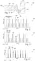
- FIG. 1 illustrates an RF communication system 150, according to an exemplary embodiment of the present disclosure.
- the RF communication system 150 comprises an RF communication device (the detecting device) 100 and two further RF communication devices 130, 140. While one further RF communication device 140 is configured as a passive device, e.g. a passive smart card, the other further RF communication device 130 is configured as an active device, here an active scanning device.
- the RF communication device 100 comprises an RF transmission device (e.g. an antenna device), configured to transmit a sequence 101 of RF signals to be received by the further RF communication devices 130, 140.
- the RF communication device 100 further comprises an adaptive detection device 120 (e.g. an IC and/or a processor), coupled to the RF transmission device 110.
- the adaptive detection device 120 is hereby configured to trigger the signal transmission by the RF transmission device 110.
- the sequence of RF signals comprises a plurality of first RF signals 111, and a plurality of second RF signals 112, transmitted in the sequence 101 subsequently one after the other.
- the adaptive detection device 120 is configured to detect the presence (and initiate a wake-up) of the active further RF communication device 130 based on the first RF signal 111, being optimized (regarding the detection distance) for high energy levels.
- the adaptive detection device 120 is further configured to detect presence (and initiate a wake-up) of the passive further RF communication device 140 based on the second RF signal 112, being optimized for low energy levels.
- the RF communication device 100 is configured here as a near field communication (NFC) device, the RF signals 111, 112 are configured as NFC signals in this example, and the RF signals 111, 112 are configured as NFC pulses.
- NFC has a standardized frequency of 13.56 MHz.
- each RF signal 111 are optimized for detecting the active further RF communication device 130 and the second RF signals 112 are optimized for detecting the passive further RF communication device 140.
- each RF signal is configured as a pulse, wherein the time duration between two pulses is 50 ms (as an exemplary time scheme).
- an adaptive detection profile is used instead of a conventional static RF energy level (power).
- the passive and the active scanning further RF communication device 130, 140, can cause the highest possible wake-up distance with optimized low power current consumption.
- a sequence of changing the energy/power level pings is used with a dedicated detection sequence (two pulses).
- Figure 3 illustrates a further sequence 101 of RF signals, according to an exemplary embodiment of the present disclosure.
- the X-axis shows the time (arbitrary units) and the Y-axis shows the energy level as RF power (arbitrary units).
- a plurality of first RF signals 111 and a plurality of second RF signals 112 are transmitted alternatingly, wherein two first RF signals 111 and two RF signals 112 are transmitted alternatingly. It can be seen that a first energy level of the first RF signal 111 is 100% higher than a second energy level of the second RF signal 112, i.e. the second energy level is only half of the first energy level.
- the double first RF signals 111 are optimized for detecting the active further RF communication device 130 and the double second RF signals 112 are optimized for detecting the passive further RF communication device 140.
- each RF signal is configured as a pulse, wherein the time duration between two pulses is 100 ms (as an exemplary time scheme.
- Figure 4 illustrates a further sequence 101 of RF signals, according to an exemplary embodiment of the present disclosure.
- the X-axis shows the time (arbitrary units) and the Y-axis shows the energy level as RF power (arbitrary units).
- the first RF signal 111 and the second RF signal 112 are transmitted together as an extended pulse that comprises two different energy levels (combining both pulses to an extended pulse with different power levels).
- Figure 5 illustrates a calibration method for a RF communication system 150, according to an exemplary embodiment of the present disclosure.
- the adaptive detection device 120 is hereby configured to: perform a calibration with respect to the first energy level of the first RF signal 111 and the second energy level of the second RF signal 112, and to derive a first reference value (refmax) for the first energy level and/or derive a second reference value (refmin) for the second energy level.
- a dedicated calibration can be done for each voltage level.
- a calibration is performed to derive the reference value of the LPCD measured parameter (e.g. RSSI, I, Q). Calibration takes then place before entering LPCD mode (the actual detection). If, during the LPCD mode, the measured LPCD parameter is higher or lower than the reference value by a specified threshold, then a wake-up will be triggered. Therefore, calibration and derivation of the reference values for both voltage levels used during LPCD mode is done.
Landscapes
- Engineering & Computer Science (AREA)
- Computer Networks & Wireless Communication (AREA)
- Signal Processing (AREA)
- Health & Medical Sciences (AREA)
- Toxicology (AREA)
- Physics & Mathematics (AREA)
- Electromagnetism (AREA)
- General Health & Medical Sciences (AREA)
- Artificial Intelligence (AREA)
- Computer Vision & Pattern Recognition (AREA)
- General Physics & Mathematics (AREA)
- Theoretical Computer Science (AREA)
- Databases & Information Systems (AREA)
- Near-Field Transmission Systems (AREA)
Priority Applications (3)
| Application Number | Priority Date | Filing Date | Title |
|---|---|---|---|
| EP23197157.3A EP4524811A1 (de) | 2023-09-13 | 2023-09-13 | Hf-kommunikationsvorrichtung zur adaptiven detektion weiterer hf-kommunikationsvorrichtungen |
| CN202411099561.1A CN119628671A (zh) | 2023-09-13 | 2024-08-12 | 用于另外的rf通信装置的自适应检测的rf通信装置 |
| US18/825,611 US20250088833A1 (en) | 2023-09-13 | 2024-09-05 | RF communication device for adaptive detection of further RF communication devices |
Applications Claiming Priority (1)
| Application Number | Priority Date | Filing Date | Title |
|---|---|---|---|
| EP23197157.3A EP4524811A1 (de) | 2023-09-13 | 2023-09-13 | Hf-kommunikationsvorrichtung zur adaptiven detektion weiterer hf-kommunikationsvorrichtungen |
Publications (1)
| Publication Number | Publication Date |
|---|---|
| EP4524811A1 true EP4524811A1 (de) | 2025-03-19 |
Family
ID=88020769
Family Applications (1)
| Application Number | Title | Priority Date | Filing Date |
|---|---|---|---|
| EP23197157.3A Pending EP4524811A1 (de) | 2023-09-13 | 2023-09-13 | Hf-kommunikationsvorrichtung zur adaptiven detektion weiterer hf-kommunikationsvorrichtungen |
Country Status (3)
| Country | Link |
|---|---|
| US (1) | US20250088833A1 (de) |
| EP (1) | EP4524811A1 (de) |
| CN (1) | CN119628671A (de) |
Citations (4)
| Publication number | Priority date | Publication date | Assignee | Title |
|---|---|---|---|---|
| EP0944014A2 (de) * | 1998-03-20 | 1999-09-22 | HID Corporation | Transpondersystem und Verfahren |
| EP2541462A2 (de) * | 2011-06-28 | 2013-01-02 | Broadcom Corporation | Verfahren und Vorrichtung zur Verringerung von NFC-Mehrfachprotokollabfragedauer und Stromverbrauch |
| US20160086002A1 (en) * | 2014-09-18 | 2016-03-24 | Samsung Electronics Co., Ltd. | Card reader and method of operating the same |
| US20180070220A1 (en) * | 2016-09-08 | 2018-03-08 | Samsung Electronics Co., Ltd. | Near field communication device |
-
2023
- 2023-09-13 EP EP23197157.3A patent/EP4524811A1/de active Pending
-
2024
- 2024-08-12 CN CN202411099561.1A patent/CN119628671A/zh active Pending
- 2024-09-05 US US18/825,611 patent/US20250088833A1/en active Pending
Patent Citations (4)
| Publication number | Priority date | Publication date | Assignee | Title |
|---|---|---|---|---|
| EP0944014A2 (de) * | 1998-03-20 | 1999-09-22 | HID Corporation | Transpondersystem und Verfahren |
| EP2541462A2 (de) * | 2011-06-28 | 2013-01-02 | Broadcom Corporation | Verfahren und Vorrichtung zur Verringerung von NFC-Mehrfachprotokollabfragedauer und Stromverbrauch |
| US20160086002A1 (en) * | 2014-09-18 | 2016-03-24 | Samsung Electronics Co., Ltd. | Card reader and method of operating the same |
| US20180070220A1 (en) * | 2016-09-08 | 2018-03-08 | Samsung Electronics Co., Ltd. | Near field communication device |
Also Published As
| Publication number | Publication date |
|---|---|
| CN119628671A (zh) | 2025-03-14 |
| US20250088833A1 (en) | 2025-03-13 |
Similar Documents
| Publication | Publication Date | Title |
|---|---|---|
| EP4028934B1 (de) | Mehrzweck-rfid-transponder und system zum lesen desselben | |
| US10650201B1 (en) | RFID tags with port-dependent functionality | |
| US8570172B2 (en) | RFID system with distributed transmitters | |
| US8704641B2 (en) | Method and communication system for controlling communication distance of RF SIM card with the aid of tag identification | |
| US10671822B1 (en) | Multipurpose RFID transponder and a system for reading it | |
| CN102246183A (zh) | 兼容的或专用的rfid标签询问和查询对话 | |
| US20120214411A1 (en) | System and method of near field communication tag presence detection for smart polling | |
| WO2023009464A3 (en) | Hybrid rfid and wireless communication system for tracking of assets and people and method thereof | |
| US11790191B2 (en) | Multipurpose RFID transponder and a system for reading it | |
| CN103340009A (zh) | 用于移动电话的多模式通信系统 | |
| EP2701314B1 (de) | Detektion von NFC lastmodulierten Signalen | |
| CN103020673A (zh) | Rfid标签的物品定位系统和定位方法 | |
| CN101404066B (zh) | 配合sim卡使用的智能卡及其数据处理方法 | |
| CN100552692C (zh) | 一种超高频射频识别读写器降功耗用的发射电路 | |
| EP2492841B1 (de) | Kommunikationsvorrichtung und Computerprogrammprodukt | |
| Chunli et al. | Application and development of RFID technique | |
| CN102682250A (zh) | 一种电池辅助式rfid标签芯片信号反射方法 | |
| EP4095754B1 (de) | Rfid-etikettenbegrenzer | |
| KR100474473B1 (ko) | 능동형 비접촉 식별장치 | |
| EP4524811A1 (de) | Hf-kommunikationsvorrichtung zur adaptiven detektion weiterer hf-kommunikationsvorrichtungen | |
| KR101136160B1 (ko) | 이중 대역 rfid 태그 | |
| KR200398970Y1 (ko) | 상이한 주파수대역을 갖는 이종의 태그가 탑재된 알에프카드 | |
| US20240297682A1 (en) | Devices and methods for near-field communication detection | |
| CN105809078A (zh) | 一种异频卡间防冲突的方法及双频读卡器 | |
| KR100701124B1 (ko) | 단말기와 연동하는 통합 전파 식별 장치 및 시스템 |
Legal Events
| Date | Code | Title | Description |
|---|---|---|---|
| PUAI | Public reference made under article 153(3) epc to a published international application that has entered the european phase |
Free format text: ORIGINAL CODE: 0009012 |
|
| STAA | Information on the status of an ep patent application or granted ep patent |
Free format text: STATUS: THE APPLICATION HAS BEEN PUBLISHED |
|
| AK | Designated contracting states |
Kind code of ref document: A1 Designated state(s): AL AT BE BG CH CY CZ DE DK EE ES FI FR GB GR HR HU IE IS IT LI LT LU LV MC ME MK MT NL NO PL PT RO RS SE SI SK SM TR |
|
| STAA | Information on the status of an ep patent application or granted ep patent |
Free format text: STATUS: REQUEST FOR EXAMINATION WAS MADE |
|
| 17P | Request for examination filed |
Effective date: 20250919 |