EP4525101A1 - Procédé de fabrication d'une pile à combustible à oxyde solide et pile à combustible à oxyde solide - Google Patents
Procédé de fabrication d'une pile à combustible à oxyde solide et pile à combustible à oxyde solide Download PDFInfo
- Publication number
- EP4525101A1 EP4525101A1 EP23197161.5A EP23197161A EP4525101A1 EP 4525101 A1 EP4525101 A1 EP 4525101A1 EP 23197161 A EP23197161 A EP 23197161A EP 4525101 A1 EP4525101 A1 EP 4525101A1
- Authority
- EP
- European Patent Office
- Prior art keywords
- coating
- anode
- sintering
- cathode
- electrolyte
- Prior art date
- Legal status (The legal status is an assumption and is not a legal conclusion. Google has not performed a legal analysis and makes no representation as to the accuracy of the status listed.)
- Pending
Links
- 239000000446 fuel Substances 0.000 title claims abstract description 37
- 238000004519 manufacturing process Methods 0.000 title claims abstract description 12
- 239000007787 solid Substances 0.000 title claims abstract description 12
- 238000000576 coating method Methods 0.000 claims abstract description 73
- 239000011248 coating agent Substances 0.000 claims abstract description 69
- 239000003792 electrolyte Substances 0.000 claims abstract description 46
- 238000005245 sintering Methods 0.000 claims abstract description 38
- 230000004888 barrier function Effects 0.000 claims abstract description 34
- 238000000034 method Methods 0.000 claims abstract description 27
- 238000007581 slurry coating method Methods 0.000 claims abstract description 27
- 239000006256 anode slurry Substances 0.000 claims abstract description 25
- 239000002002 slurry Substances 0.000 claims description 28
- 229910002080 8 mol% Y2O3 fully stabilized ZrO2 Inorganic materials 0.000 claims description 26
- OKTJSMMVPCPJKN-UHFFFAOYSA-N Carbon Chemical compound [C] OKTJSMMVPCPJKN-UHFFFAOYSA-N 0.000 claims description 19
- 229910002804 graphite Inorganic materials 0.000 claims description 19
- 239000010439 graphite Substances 0.000 claims description 19
- 229910001233 yttria-stabilized zirconia Inorganic materials 0.000 claims description 14
- BQCADISMDOOEFD-UHFFFAOYSA-N Silver Chemical compound [Ag] BQCADISMDOOEFD-UHFFFAOYSA-N 0.000 claims description 11
- 229910052709 silver Inorganic materials 0.000 claims description 11
- 239000004332 silver Substances 0.000 claims description 11
- MCMNRKCIXSYSNV-UHFFFAOYSA-N Zirconium dioxide Chemical compound O=[Zr]=O MCMNRKCIXSYSNV-UHFFFAOYSA-N 0.000 claims description 8
- 238000001035 drying Methods 0.000 claims description 7
- 238000003618 dip coating Methods 0.000 claims description 6
- 238000007598 dipping method Methods 0.000 claims description 6
- 229910052760 oxygen Inorganic materials 0.000 claims description 5
- 238000003698 laser cutting Methods 0.000 claims description 4
- 229910052684 Cerium Inorganic materials 0.000 claims description 2
- 229910052688 Gadolinium Inorganic materials 0.000 claims description 2
- 229910052746 lanthanum Inorganic materials 0.000 claims description 2
- 229910052712 strontium Inorganic materials 0.000 claims description 2
- LFQSCWFLJHTTHZ-UHFFFAOYSA-N Ethanol Chemical compound CCO LFQSCWFLJHTTHZ-UHFFFAOYSA-N 0.000 description 46
- 229920002037 poly(vinyl butyral) polymer Polymers 0.000 description 44
- 229910021526 gadolinium-doped ceria Inorganic materials 0.000 description 18
- 238000010438 heat treatment Methods 0.000 description 15
- 239000000725 suspension Substances 0.000 description 10
- MQIUGAXCHLFZKX-UHFFFAOYSA-N Di-n-octyl phthalate Natural products CCCCCCCCOC(=O)C1=CC=CC=C1C(=O)OCCCCCCCC MQIUGAXCHLFZKX-UHFFFAOYSA-N 0.000 description 9
- BJQHLKABXJIVAM-UHFFFAOYSA-N bis(2-ethylhexyl) phthalate Chemical compound CCCCC(CC)COC(=O)C1=CC=CC=C1C(=O)OCC(CC)CCCC BJQHLKABXJIVAM-UHFFFAOYSA-N 0.000 description 9
- 238000003756 stirring Methods 0.000 description 9
- 241000273930 Brevoortia tyrannus Species 0.000 description 8
- 235000021323 fish oil Nutrition 0.000 description 8
- 238000002156 mixing Methods 0.000 description 7
- 239000000843 powder Substances 0.000 description 7
- 239000002202 Polyethylene glycol Substances 0.000 description 6
- 238000001816 cooling Methods 0.000 description 6
- 230000008021 deposition Effects 0.000 description 6
- 229920001223 polyethylene glycol Polymers 0.000 description 6
- 239000011230 binding agent Substances 0.000 description 5
- 239000000463 material Substances 0.000 description 5
- 239000000203 mixture Substances 0.000 description 5
- 239000000758 substrate Substances 0.000 description 5
- 230000007547 defect Effects 0.000 description 4
- 239000007789 gas Substances 0.000 description 4
- 238000001000 micrograph Methods 0.000 description 4
- 239000004014 plasticizer Substances 0.000 description 4
- 229920002451 polyvinyl alcohol Polymers 0.000 description 4
- 229920002565 Polyethylene Glycol 400 Polymers 0.000 description 3
- 239000004372 Polyvinyl alcohol Substances 0.000 description 3
- 238000003760 magnetic stirring Methods 0.000 description 3
- 229920002113 octoxynol Polymers 0.000 description 3
- 239000011148 porous material Substances 0.000 description 3
- 229910002607 Gd0.1Ce0.9O1.95 Inorganic materials 0.000 description 2
- 229910002138 La0.6Sr0.4CoO3 Inorganic materials 0.000 description 2
- 229910009474 Y2O3—ZrO2 Inorganic materials 0.000 description 2
- PBAYDYUZOSNJGU-UHFFFAOYSA-N chelidonic acid Natural products OC(=O)C1=CC(=O)C=C(C(O)=O)O1 PBAYDYUZOSNJGU-UHFFFAOYSA-N 0.000 description 2
- 238000010586 diagram Methods 0.000 description 2
- 239000002270 dispersing agent Substances 0.000 description 2
- 150000002500 ions Chemical class 0.000 description 2
- 229910052751 metal Inorganic materials 0.000 description 2
- 239000002184 metal Substances 0.000 description 2
- 238000010422 painting Methods 0.000 description 2
- 238000002360 preparation method Methods 0.000 description 2
- 238000007639 printing Methods 0.000 description 2
- 238000001878 scanning electron micrograph Methods 0.000 description 2
- 239000002904 solvent Substances 0.000 description 2
- XLYOFNOQVPJJNP-UHFFFAOYSA-N water Substances O XLYOFNOQVPJJNP-UHFFFAOYSA-N 0.000 description 2
- UFHFLCQGNIYNRP-UHFFFAOYSA-N Hydrogen Chemical compound [H][H] UFHFLCQGNIYNRP-UHFFFAOYSA-N 0.000 description 1
- PACGUUNWTMTWCF-UHFFFAOYSA-N [Sr].[La] Chemical compound [Sr].[La] PACGUUNWTMTWCF-UHFFFAOYSA-N 0.000 description 1
- 239000010405 anode material Substances 0.000 description 1
- QVGXLLKOCUKJST-UHFFFAOYSA-N atomic oxygen Chemical compound [O] QVGXLLKOCUKJST-UHFFFAOYSA-N 0.000 description 1
- 229910052799 carbon Inorganic materials 0.000 description 1
- 229910052963 cobaltite Inorganic materials 0.000 description 1
- 238000010276 construction Methods 0.000 description 1
- 230000003247 decreasing effect Effects 0.000 description 1
- 230000001419 dependent effect Effects 0.000 description 1
- 239000006185 dispersion Substances 0.000 description 1
- 238000004090 dissolution Methods 0.000 description 1
- 230000000694 effects Effects 0.000 description 1
- 238000010304 firing Methods 0.000 description 1
- 239000001257 hydrogen Substances 0.000 description 1
- 229910052739 hydrogen Inorganic materials 0.000 description 1
- 238000007654 immersion Methods 0.000 description 1
- 230000000873 masking effect Effects 0.000 description 1
- 229910000480 nickel oxide Inorganic materials 0.000 description 1
- GNRSAWUEBMWBQH-UHFFFAOYSA-N oxonickel Chemical compound [Ni]=O GNRSAWUEBMWBQH-UHFFFAOYSA-N 0.000 description 1
- 239000001301 oxygen Substances 0.000 description 1
- 229920005597 polymer membrane Polymers 0.000 description 1
- 238000002203 pretreatment Methods 0.000 description 1
- 238000006722 reduction reaction Methods 0.000 description 1
- 238000004062 sedimentation Methods 0.000 description 1
- 238000000926 separation method Methods 0.000 description 1
- 239000004449 solid propellant Substances 0.000 description 1
- 230000008646 thermal stress Effects 0.000 description 1
- 239000013585 weight reducing agent Substances 0.000 description 1
- 238000009736 wetting Methods 0.000 description 1
Images


Classifications
-
- H—ELECTRICITY
- H01—ELECTRIC ELEMENTS
- H01M—PROCESSES OR MEANS, e.g. BATTERIES, FOR THE DIRECT CONVERSION OF CHEMICAL ENERGY INTO ELECTRICAL ENERGY
- H01M8/00—Fuel cells; Manufacture thereof
- H01M8/10—Fuel cells with solid electrolytes
- H01M8/12—Fuel cells with solid electrolytes operating at high temperature, e.g. with stabilised ZrO2 electrolyte
- H01M8/124—Fuel cells with solid electrolytes operating at high temperature, e.g. with stabilised ZrO2 electrolyte characterised by the process of manufacturing or by the material of the electrolyte
- H01M8/1246—Fuel cells with solid electrolytes operating at high temperature, e.g. with stabilised ZrO2 electrolyte characterised by the process of manufacturing or by the material of the electrolyte the electrolyte consisting of oxides
- H01M8/1253—Fuel cells with solid electrolytes operating at high temperature, e.g. with stabilised ZrO2 electrolyte characterised by the process of manufacturing or by the material of the electrolyte the electrolyte consisting of oxides the electrolyte containing zirconium oxide
-
- H—ELECTRICITY
- H01—ELECTRIC ELEMENTS
- H01M—PROCESSES OR MEANS, e.g. BATTERIES, FOR THE DIRECT CONVERSION OF CHEMICAL ENERGY INTO ELECTRICAL ENERGY
- H01M4/00—Electrodes
- H01M4/86—Inert electrodes with catalytic activity, e.g. for fuel cells
- H01M4/88—Processes of manufacture
- H01M4/8825—Methods for deposition of the catalytic active composition
- H01M4/8828—Coating with slurry or ink
-
- H—ELECTRICITY
- H01—ELECTRIC ELEMENTS
- H01M—PROCESSES OR MEANS, e.g. BATTERIES, FOR THE DIRECT CONVERSION OF CHEMICAL ENERGY INTO ELECTRICAL ENERGY
- H01M4/00—Electrodes
- H01M4/86—Inert electrodes with catalytic activity, e.g. for fuel cells
- H01M4/90—Selection of catalytic material
- H01M4/9016—Oxides, hydroxides or oxygenated metallic salts
- H01M4/9025—Oxides specially used in fuel cell operating at high temperature, e.g. SOFC
-
- H—ELECTRICITY
- H01—ELECTRIC ELEMENTS
- H01M—PROCESSES OR MEANS, e.g. BATTERIES, FOR THE DIRECT CONVERSION OF CHEMICAL ENERGY INTO ELECTRICAL ENERGY
- H01M8/00—Fuel cells; Manufacture thereof
- H01M8/002—Shape, form of a fuel cell
- H01M8/004—Cylindrical, tubular or wound
-
- H—ELECTRICITY
- H01—ELECTRIC ELEMENTS
- H01M—PROCESSES OR MEANS, e.g. BATTERIES, FOR THE DIRECT CONVERSION OF CHEMICAL ENERGY INTO ELECTRICAL ENERGY
- H01M8/00—Fuel cells; Manufacture thereof
- H01M8/10—Fuel cells with solid electrolytes
- H01M8/12—Fuel cells with solid electrolytes operating at high temperature, e.g. with stabilised ZrO2 electrolyte
- H01M2008/1293—Fuel cells with solid oxide electrolytes
-
- H—ELECTRICITY
- H01—ELECTRIC ELEMENTS
- H01M—PROCESSES OR MEANS, e.g. BATTERIES, FOR THE DIRECT CONVERSION OF CHEMICAL ENERGY INTO ELECTRICAL ENERGY
- H01M4/00—Electrodes
- H01M4/86—Inert electrodes with catalytic activity, e.g. for fuel cells
- H01M4/88—Processes of manufacture
- H01M4/8803—Supports for the deposition of the catalytic active composition
- H01M4/8814—Temporary supports, e.g. decal
-
- H—ELECTRICITY
- H01—ELECTRIC ELEMENTS
- H01M—PROCESSES OR MEANS, e.g. BATTERIES, FOR THE DIRECT CONVERSION OF CHEMICAL ENERGY INTO ELECTRICAL ENERGY
- H01M8/00—Fuel cells; Manufacture thereof
- H01M8/10—Fuel cells with solid electrolytes
- H01M8/12—Fuel cells with solid electrolytes operating at high temperature, e.g. with stabilised ZrO2 electrolyte
- H01M8/1213—Fuel cells with solid electrolytes operating at high temperature, e.g. with stabilised ZrO2 electrolyte characterised by the electrode/electrolyte combination or the supporting material
-
- H—ELECTRICITY
- H01—ELECTRIC ELEMENTS
- H01M—PROCESSES OR MEANS, e.g. BATTERIES, FOR THE DIRECT CONVERSION OF CHEMICAL ENERGY INTO ELECTRICAL ENERGY
- H01M8/00—Fuel cells; Manufacture thereof
- H01M8/10—Fuel cells with solid electrolytes
- H01M8/12—Fuel cells with solid electrolytes operating at high temperature, e.g. with stabilised ZrO2 electrolyte
- H01M8/1213—Fuel cells with solid electrolytes operating at high temperature, e.g. with stabilised ZrO2 electrolyte characterised by the electrode/electrolyte combination or the supporting material
- H01M8/1226—Fuel cells with solid electrolytes operating at high temperature, e.g. with stabilised ZrO2 electrolyte characterised by the electrode/electrolyte combination or the supporting material characterised by the supporting layer
-
- Y—GENERAL TAGGING OF NEW TECHNOLOGICAL DEVELOPMENTS; GENERAL TAGGING OF CROSS-SECTIONAL TECHNOLOGIES SPANNING OVER SEVERAL SECTIONS OF THE IPC; TECHNICAL SUBJECTS COVERED BY FORMER USPC CROSS-REFERENCE ART COLLECTIONS [XRACs] AND DIGESTS
- Y02—TECHNOLOGIES OR APPLICATIONS FOR MITIGATION OR ADAPTATION AGAINST CLIMATE CHANGE
- Y02E—REDUCTION OF GREENHOUSE GAS [GHG] EMISSIONS, RELATED TO ENERGY GENERATION, TRANSMISSION OR DISTRIBUTION
- Y02E60/00—Enabling technologies; Technologies with a potential or indirect contribution to GHG emissions mitigation
- Y02E60/30—Hydrogen technology
- Y02E60/50—Fuel cells
-
- Y—GENERAL TAGGING OF NEW TECHNOLOGICAL DEVELOPMENTS; GENERAL TAGGING OF CROSS-SECTIONAL TECHNOLOGIES SPANNING OVER SEVERAL SECTIONS OF THE IPC; TECHNICAL SUBJECTS COVERED BY FORMER USPC CROSS-REFERENCE ART COLLECTIONS [XRACs] AND DIGESTS
- Y02—TECHNOLOGIES OR APPLICATIONS FOR MITIGATION OR ADAPTATION AGAINST CLIMATE CHANGE
- Y02P—CLIMATE CHANGE MITIGATION TECHNOLOGIES IN THE PRODUCTION OR PROCESSING OF GOODS
- Y02P70/00—Climate change mitigation technologies in the production process for final industrial or consumer products
- Y02P70/50—Manufacturing or production processes characterised by the final manufactured product
Definitions
- the present disclosure generally relates to a method of fabricating a solid oxide fuel cell and a corresponding fuel cell. Particularly, the present disclosure relates to a method of fabricating a solid oxide fuel cell including pre-sintering an anode slurry coating and applying an electrolyte, barrier and cathode coating sintered onto the anode. The present disclosure further relates to a solid oxide fuel cell manufactured by such method.
- the fuel cells can include polymer membrane fuel cells, which can operate at lower temperatures, particularly below 200°C, as well as solid fuel cells (e.g., solid oxide fuel cells, SOFC), which operate at higher temperatures, particularly between 500°C and 1000°C.
- polymer membrane fuel cells which can operate at lower temperatures, particularly below 200°C
- solid fuel cells e.g., solid oxide fuel cells, SOFC
- SOFCs provide a high electrical and thermal energy efficiency, with a high fuel utilisation up to 85%.
- An oxygen reduction reaction occurs in a porous cathode of the SOFC by accepting electrons and producing oxide ions which transfer through a gas tight electrolyte to an anode interface.
- the hydrogen fuel gets oxidised at the anode interface by accepting the oxide ions and producing electrons, which pass to the cathode side through an external circuit.
- the electrolyte (layer) provides mechanical stability to the SOFC, which is necessary, particularly due to thermal stress. Thus, a thick electrolyte is desirable from a mechanical standpoint. However, the ohmic resistance of the electrolyte is high, particularly in case of a thick electrolyte layer.
- a method of fabricating a solid oxide fuel cell comprises applying an anode slurry coating, pre-sintering the anode slurry coating forming an anode of the SOFC, and applying an electrolyte coating and a barrier coating on the anode.
- an anode supported fuel cell can be fabricated, which offers considerable mechanical strength for the fuel cell due to the anode material.
- the pre-sintered anode provides the opportunity of having only a thin electrolyte part.
- the method further comprises applying a cathode coating on the barrier coating, and sintering the anode and the applied electrolyte, barrier and cathode coating.
- the anode supported fuel cell allows a weight reduction of the entire cell compared, for example, with an electrolyte supported cell or a planar SOFC.
- the pre-sintering of the anode slurry coating is performed with a temperature between 800°C and 1200°C, preferably at 1000°C.
- the anode slurry coating can be heated from ambient temperature (room temperature) to 1000°C with a heating rate of 0.5°C/min.
- the temperature of 1000°C can be maintained for 1.5 to 2.5 hours, preferably 2 hours.
- the pre-sintered anode may cool down naturally to room temperature, i.e. in an environment at room temperature.
- the method can further comprise applying a current collector coating on the cathode coating, and sintering the current collector coating.
- the current collector coating allows a better electric connectivity.
- the sintering after applying the current collector is performed at a temperature between 100°C and 900°C, preferably at 100°C and 800°C.
- the temperature is raised from room temperature to 100°C with a heating rate of 0.5°C/min (i.e., in 200 minutes).
- the temperature of 100°C is held for 1 hour and is then further increased to 800°C at 1°C/min (i.e., in 700 minutes).
- the sample is cooled down to room temperature with a cooling rate of 3°C/min.
- the method can further comprise co-sintering the electrolyte coating and the barrier coating before applying the cathode coating.
- the electrolyte and barrier coating allow decreasing of the ohmic resistance of the electrolyte and further provides a dense structure preventing a gas leakage, i.e., the electrolyte layer is gas tight, and at the same time provides a high structural stability.
- the co-sintering is performed at a temperature between 600°C and 1500°C, preferably at 600°C, 850°C and 1350°C.
- the co-sintering is performed in several steps, starting with heating from room temperature to 600°C with a heating rate of 0.6°C/min (i.e., for approximately 1000 minutes).
- the temperature of 600°C is held for 1 hour, which allows removing a binder and organic components present in the electrolyte and/or barrier coating. Thereafter, the temperature is increased to 850°C with a heating rate of 3.3°C/min (i.e., in about 75 minutes).
- This temperature is held for 15 minutes, subsequently raised to 1350°C with a heating rate of 10°C/min (i.e., in about 50 minutes), and held at 1350°C for 3 hours. After sintering, the sample is cooled down to room temperature at a cooling rate of 3°C/min.
- the sintering of the cathode coating i.e. the sintering after applying the cathode coating (but before applying a current collector coating) is performed at a temperature between 600°C and 1100°C, preferably at 600°C and 950°C.
- the sintering of the cathode coating is performed in several steps, starting with heating from room temperature to 600°C with a heating rate of 0.6°C/min (i.e., for approximately 1000 minutes). The temperature of 600°C is held for 1 hour, which allows removing a binder and organic components present in cathode coating.
- the temperature is increased to 950°C with a heating rate of 1°C/min (i.e., in about 350 minutes), and is held for 1 hour.
- the sample is cooled down to room temperature at a cooling rate of 3°C/min.
- the method can further comprise laser cutting the pre-sintered anode at at least one edge of the anode. This allows removing portions of the anode having cracks or similar defects in a region close to the edge. Such cracks can result from the pre-sintering.
- the graphite mould can be configured to disintegrate during the pre-sintering.
- the graphite mould disintegrates and can be removed, so that any further fabrication steps can be performed solely with the pre-sintered anode.
- the electrolyte slurry coating can be made from the following components having the respective given proportion (relative to the entire sum of components): adding Y 2 O 3 -ZrO 2 8YSZ-PSD(d50) powder (18 to 22%, preferably 20%) to ethanol absolute (EtOH) (71 to 87%, preferably 78.9%), Fish oil menhaden (MFO) (0.16 to 0.19%, preferably 0.18%) and Polyvinyl Butyral (PVB; such as Butvar B-98) (0.8 to 1%, preferably 0.9%), and stirring the suspension for 3 hours.
- EtOH ethanol absolute
- MFO Fish oil menhaden
- PVB Polyvinyl Butyral
- Butvar B-98 Polyvinyl Butyral
- the fuel cell can further comprise a silver current collector having a thickness between 6 and 14 ⁇ m, preferably 10 ⁇ m.
- the SOFC has a tubular body.
- the anode can have a length of 40 to 60 mm, preferably 50 mm, and/or the electrolyte can have a length of 30 to 50 mm, preferably 40 mm, and/or the barrier layer can have a length of 30 to 50 mm, preferably 40 mm, and most preferably can have the same length as the electrolyte, and/or the cathode can have a length of 20 to 40 mm, preferably 30 mm, and/or the silver current collector can have a length of 20 to 40 mm, preferably 30 mm, and most preferably can have the same length as the cathode.
- FIG 1 schematically illustrates a cross-section of an exemplary fuel cell 100 and a detail of a portion thereof.
- the exemplary fuel cell 100 is a solid oxide fuel cell 100 having an annular shape.
- the cross-section of the SOFC 100 includes an innermost body forming an anode 130.
- the anode 130 is covered (on its outside) by an electrolyte layer 140 followed by a barrier layer 145.
- the barrier layer 145 is surrounded on its outside by a cathode layer 150. At least on portions of the cathode layer 150 there may be provided a current collector 160.
- the anode can be made from or can contain NiO-YSZ (Nickel oxide - Yttria-stabilized zirconia), particularly NiO-8YSZ (with 8 mol% Y 2 O 3 fully stabilized ZrO 2 ), the electrolyte layer 140 can be made from or can contain YSZ, the barrier layer 145 can be made from or can contain GDC (Gadolinium-doped ceria), the cathode layer 150 can be made from or can contain LSC (Lanthanum Strontium Cobaltite), and the current collector 160 can be made from or can contain silver.
- NiO-YSZ Nickel oxide - Yttria-stabilized zirconia
- NiO-8YSZ with 8 mol% Y 2 O 3 fully stabilized ZrO 2
- FIG 2 schematically illustrates steps of fabricating an exemplary SOFC 100.
- a graphite rod 110 is dipped in an NiO-8YSZ slurry, so that a slurry dip coating 120 at years to the graphite rod 110.
- the graphite rod 110 disintegrates and leaves a preliminary anode 125.
- Such preliminary anode 125 may have cracks 127 or other defects were particularly in an edge region.
- Such cracks 127 or other defects can be removed by laser cutting the preliminary anode 125 along its edges.
- the cut anode 130 is then dip coated twice with a slurry, so that an electrolyte coating 140 and a barrier coating 145 are formed on the anode 130.
- Figure 2 only illustrates the outer barrier coating 145, as it mainly covers the electrolyte coating 140.
- a cathode coating 150 is applied.
- the cathode coating 150 can again be hardened by sintering.
- a current collector coating 160 can be applied, by dipping, painting, ink printing or the like. After a final sintering the SOFC 100 is fully fabricated.
- Figure 3 schematically illustrates a flow diagram of a method of fabricating a fuel cell, particularly an annular SOFC 100. The method steps illustrated in Figure 3 are also indicated in the flow illustrated in Figure 2 for comparability of both drawings.
- the method includes applying in step S220 an anode slurry coating 120, that is, in step S230, pre-sintered to form a (preliminary) anode 125, 130. Furthermore, in step S240, an electrolyte coating 140 and a barrier coating 145 are applied. Thereafter, cathode coating 150 is applied in step S250. The applying of the coatings 120, 140, 145 can be performed by slurry dipping. Thereafter, the applied electrolyte, barrier and cathode coating 140, 145, 150 on the anode 125, 130 is sintered in a step S255.
- the method can include several optional steps, which are illustrated in dashed lines in Figure 3 .
- step S210 This includes, in step S210, providing a graphite mould 110 that is configured to disintegrate during the pre-sintering (step S230).
- the graphite mould 110 can be used to apply the anode slurry coating 120 thereon in step S220, for example, by slurry dipping.
- the anode slurry coating 120 can be dried for at least 12 hours, preferably at least 24-hour is in air. The drying can be performed at room temperature. As indicated above with respect to Figure 2 , if any cracks 127 or other defects are present, in step S235, at least one edge of the present third anode 125 can be cut, for example employing laser cutting.
- step S245 the electrolyte coating 140 and the barrier coating 145 can be co-sintered before applying the cathode coating 150.
- a current collector coating can be applied to the cathode coating/layer 150. This applying can be performed by painting, ink printing, dipping or the like.
- the current collector coating 160 can be sintered in step S265.
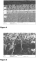
- Figure 4 illustrates a microscope image of a layer build-up of a fuel cell 100 fabricated by the method of Figure 3 .
- the image (photograph) is made with a scanning electron microscope (SEM) and shows a portion of the anode 130 (indicated by a)), an approximately 8 ⁇ m thick 8YSZ film forming the electrolyte layer 140 (indicated by b)), followed by the approximately 3.5 ⁇ m thick GDC barrier layer 145 (indicated by c)), and the approximately 20 ⁇ m thick LSC cathode layer 150 (indicated by d)).
- the dark component at the top of Figure 4 is a portion of the silver current collector.
- Figure 5 illustrates another microscope image of a portion of the layer build-up of Figure 4 with greater magnification (e.g., mag. 5000x), and was also made by an SEM.
- Figure 5 shows the morphology of the coating system, particularly of the electrolyte layer 140 (YSZ), the barrier layer 145 (GDC), and the cathode layer 150 (LSC).
- the following example shows possible mixtures to compose the respective slurry, in order to fabricate an annular SOFC 100.
- the SOFC 100 is made by slurry dip-coating.
- the exemplary materials and their respective proportion relative to the entire slurry are summarized in table 1 below: Table 1: Used materials for slurry preparation (proportionate percentage ranges; and specific exemplary percentage value).
- Table 2 shows ranges of weight, and one specific weight value, for each component to compose the respective slurry: Table 2: Used materials for slurry preparation (ranges of weight; plus specific exemplary weight).
- Ethanol absolute (EtOH) (102 to 114 g; 108 g )
- Triton TM X-100 (4 to 5 g; 4.5 g)
- PVB Polyvinyl butyral Butvar B-98 (PVB) ( 10.8 to 13.2 g; 12 g)
- DOP Dioctyl Phthalate
- NiO-8YSZ powder was added to 50 g of the ethanol containing 4.5 g Triton X.
- the Suspension was magnetically stirred for 30 minutes at high speed (for example, at 4000-6000rpm).
- 12 g of PVB was solubilized in 58 g of ethanol.
- the mixture was slightly heated between 45 - 50° C using a hot water bath for complete solubilisation of the PVB.
- the PVB solution was magnetically stirred for 30 minutes.
- the PVB solution was added to the NiO/YSZ suspension under magnetic stirring.
- the mixture was stirred for 30 minutes before adding 4.5 g of PEG 400 and 4.5 g of DOP.
- the slurry was magnetically stirred for another 30 minutes and then mixed at high speed (6000 rpm) for 5 minutes using an Ultra Turrax.
- the slurry 120 was then kept in the fridge before use and mixed again at high speed for 5 min (6000 rpm) shortly before use.
- a graphite rod 110 was dipped (S220) for 15 seconds in a NiO-8YSZ slurry prepared according to the procedure described above.
- the deposited layer 120 was redrawn at a 125 mm/min speed.
- the deposit layer 120 was dried in the air for 10 minutes.
- the deposition cycle (S220) was repeated 12 times in order to reach the desired anode thickness.
- the anode support was dried in air (S225) for more than 24 h before a pre-firing step (S230).
- the support 110, 120 was heated from ambient temperature to 1000 °C using a heating rate of 0.5 °C/min, the temperature was then maintained at 1000 °C for 2 h and finally the support 125 was allowed to naturally cool down to room temperature.
- NiO-8YSZ pre-sintered tubes 125 are cut (S235) by a laser (Rofin Powerline E 25, short Pulsed IR Laser (25 W) 1064 nm) to adjust the tube length and remove the cracked edges 127.
- a laser Renin Powerline E 25, short Pulsed IR Laser (25 W) 1064 nm
- PVA Polyvinyl alcohol
- S220, S240 the substrates are cleaned with ethanol and then treated in air plasma (0.2 mbar, 1000 W, 1 min) to improve the wettability.
- air plasma 0.2 mbar, 1000 W, 1 min
- the 8YSZ, GDC and LSC slurry compositions 120, 140, 145 are available in Tables 1 and 2.
- the 8YSZ and GDC slurries 120, 140 are mixed using magnetic stirring for 3 h. This stirring is followed by a high speed mixing at 1300 rpm for 5 min (Hauschild, DAC 150 FVZ) in order to achieve a better dispersion and homogeneity of the suspensions.
- 8YSZ and GDC slurries 120, 140 are allowed to settle for 30 minutes before starting the deposition (S220, S240) in order to allow sedimentation of hypothetical agglomerates.
- the 8YSZ electrolyte film 140 and the GDC barrier layer 145 applied (S240) on the pre-sintered anode tube (125, 130) are co-sintered (S245) at 1350°C for 3 hours.
- the sintering (S245) is performed in several steps: heating from RT to 600 °C in approx. 1000 min. (0.6 °C/min heating rate). The 600 °C is held for 1 hour to remove the binder and other organic components. Then the temperature is increased to 850 °C in 75 min (3.3 °C/min), held for 15 min and subsequently raised in 50 min (10 °C/min) to 1350 °C which is held for 3 hours. Afterward, the samples are cooled to room temperature (RT) at 3 °C/min.
- the LSC cathode layer 150 is sintered (S250) at 950 °C for 1 hour.
- the same debindering step as before is used followed by an increase to 950 °C in 350 min (1°C/min).
- the controlled cooling to RT uses a cooling rate of 3 °C/min.
- the silver layer 160 is sintered (S265) at 800 °C for 1 hour.
- the temperature is raised from RT to 100 °C in approx. 200 min. (0.5 °C/min), held there for 1 hour and is then further increased to 800 °C in 700 min (1 °C/min).
- After 1 hour sintering at 800 °C the samples 100 are cooled down to RT at a cooling rate of 3 °C/min.
- the coating system is composed of an approx. 8 ⁇ m thick 8YSZ film 140 ( Figure 4 , b) on top of the NiO-8YSZ anode tube 130 ( Figure 4 , a) followed by the approx. 3.5 ⁇ m thick GDC barrier layer 145 ( Figure 4 , c) and the approx. 20 ⁇ m thick LSC cathode layer 150 ( Figure 4 , d).
- Figure 5 shows the morphology of the coating system at higher magnification of mag. 5000 x.
- the 8YSZ electrolyte film 140 has isolated closed pores and is close to full density.
- the GDC barrier layer 145 shows some pores. However, these are closed pores which should lead to an effective separation between the electrolyte film 140 and the cathode layer 150.
- the LSC layer 150 shows a porosity of approx. 40 %. The porosity is estimated by image processing software.
Landscapes
- Engineering & Computer Science (AREA)
- Chemical & Material Sciences (AREA)
- Manufacturing & Machinery (AREA)
- Chemical Kinetics & Catalysis (AREA)
- Electrochemistry (AREA)
- General Chemical & Material Sciences (AREA)
- Life Sciences & Earth Sciences (AREA)
- Sustainable Development (AREA)
- Sustainable Energy (AREA)
- Materials Engineering (AREA)
- Inert Electrodes (AREA)
Priority Applications (1)
| Application Number | Priority Date | Filing Date | Title |
|---|---|---|---|
| EP23197161.5A EP4525101A1 (fr) | 2023-09-13 | 2023-09-13 | Procédé de fabrication d'une pile à combustible à oxyde solide et pile à combustible à oxyde solide |
Applications Claiming Priority (1)
| Application Number | Priority Date | Filing Date | Title |
|---|---|---|---|
| EP23197161.5A EP4525101A1 (fr) | 2023-09-13 | 2023-09-13 | Procédé de fabrication d'une pile à combustible à oxyde solide et pile à combustible à oxyde solide |
Publications (1)
| Publication Number | Publication Date |
|---|---|
| EP4525101A1 true EP4525101A1 (fr) | 2025-03-19 |
Family
ID=88021045
Family Applications (1)
| Application Number | Title | Priority Date | Filing Date |
|---|---|---|---|
| EP23197161.5A Pending EP4525101A1 (fr) | 2023-09-13 | 2023-09-13 | Procédé de fabrication d'une pile à combustible à oxyde solide et pile à combustible à oxyde solide |
Country Status (1)
| Country | Link |
|---|---|
| EP (1) | EP4525101A1 (fr) |
Citations (2)
| Publication number | Priority date | Publication date | Assignee | Title |
|---|---|---|---|---|
| US20080286625A1 (en) * | 2007-03-26 | 2008-11-20 | Alberta Research Council Inc. | Solid state electrochemical cell having reticulated electrode matrix and method of manufacturing same |
| US8182959B2 (en) * | 2007-11-06 | 2012-05-22 | Cp Sofc Ip, Llc | Tubular electrochemical cell |
-
2023
- 2023-09-13 EP EP23197161.5A patent/EP4525101A1/fr active Pending
Patent Citations (2)
| Publication number | Priority date | Publication date | Assignee | Title |
|---|---|---|---|---|
| US20080286625A1 (en) * | 2007-03-26 | 2008-11-20 | Alberta Research Council Inc. | Solid state electrochemical cell having reticulated electrode matrix and method of manufacturing same |
| US8182959B2 (en) * | 2007-11-06 | 2012-05-22 | Cp Sofc Ip, Llc | Tubular electrochemical cell |
Non-Patent Citations (2)
| Title |
|---|
| HAN ZONGYING ET AL: "Optimization of Ni-YSZ anodes for tubular SOFC by a novel and efficient phase inversion-impregnation approach", JOURNAL OF ALLOYS AND COMPOUNDS, ELSEVIER SEQUOIA, LAUSANNE, CH, vol. 750, 13 February 2018 (2018-02-13), pages 130 - 138, XP085385750, ISSN: 0925-8388, DOI: 10.1016/J.JALLCOM.2018.02.135 * |
| MAJHI S M ET AL: "Anode supported solid oxide fuel cells (SOFC) by electrophoretic deposition", INTERNATIONAL JOURNAL OF HYDROGEN ENERGY, ELSEVIER, AMSTERDAM, NL, vol. 36, no. 22, 18 February 2011 (2011-02-18), pages 14930 - 14935, XP028314962, ISSN: 0360-3199, [retrieved on 20110224], DOI: 10.1016/J.IJHYDENE.2011.02.100 * |
Similar Documents
| Publication | Publication Date | Title |
|---|---|---|
| KR100344936B1 (ko) | 연료극 지지체식 원통형 고체산화물 연료전지 및 그 제조방법 | |
| CA2745575C (fr) | Procede pour le depot de films ceramiques | |
| Will et al. | Electrophoretic deposition of zirconia on porous anodic substrates | |
| KR100717130B1 (ko) | 고체산화물 연료전지용 페이스트, 이를 이용한 연료극지지형 고체산화물 연료전지 및 그 제조 방법 | |
| US8940455B2 (en) | Fuel cell | |
| CA2680534C (fr) | Cellule electrochimique solide comprenant une matrice d'electrode reticulee et procede de fabrication correspondant | |
| JP7780438B2 (ja) | 固体酸化物用中間層 | |
| KR102436926B1 (ko) | 전기 화학 소자, 고체 산화물형 연료 전지 셀, 및 이들의 제조 방법 | |
| CN101562255A (zh) | 一种金属支撑型固体氧化物燃料电池的制备方法 | |
| CN101137456A (zh) | 在烧结多层结构时控制收缩率和孔隙率的方法 | |
| JP2024510216A (ja) | 金属支持体電気化学セル用金属基板 | |
| KR20130092368A (ko) | 정전 분무 슬러리 증착 공정을 이용한 원통형 고체산화물 연료전지의 제조방법 | |
| EP2973822A1 (fr) | Pile à combustible céramique ayant une planéité améliorée et une résistance améliorée et ses procédés de fabrication | |
| US9799908B2 (en) | Method of preparing an electrochemical half-cell | |
| KR102600903B1 (ko) | 광소결을 이용한 금속지지형 고체산화물 연료전지의 제조방법 | |
| KR101657242B1 (ko) | 반응방지막을 포함하는 고온 고체산화물 셀, 이의 제조방법 | |
| KR20110004274A (ko) | 고체산화물 연료전지의 제조방법 | |
| KR20190129841A (ko) | 전기 화학 소자의 제조 방법 및 전기 화학 소자 | |
| JP3350313B2 (ja) | 固体電解質型燃料電池セルおよびその製造方法 | |
| KR20210046077A (ko) | 세라믹-애노드 고체 산화물 연료 전지에 대한 세터 플레이트 및 제조 방법 | |
| WO2014203066A2 (fr) | Procédé et appareil de fabrication d'une pile à combustible d'oxyde solide | |
| US20100297527A1 (en) | Fast Ion Conducting Composite Electrolyte for Solid State Electrochemical Devices | |
| KR101220772B1 (ko) | 고체산화물 연료전지의 제조방법 | |
| KR100833626B1 (ko) | 서멧 전해질을 사용하는 애노드 지지된 고체 산화물 연료 전지 | |
| KR101542906B1 (ko) | 이트리아 안정화 지르코니아(ysz) 및 이트리아(y2o3)를 포함하는 복합재료를 포함하는 전해질 및 이를 이용한 전해질층 제조방법 |
Legal Events
| Date | Code | Title | Description |
|---|---|---|---|
| PUAI | Public reference made under article 153(3) epc to a published international application that has entered the european phase |
Free format text: ORIGINAL CODE: 0009012 |
|
| STAA | Information on the status of an ep patent application or granted ep patent |
Free format text: STATUS: REQUEST FOR EXAMINATION WAS MADE |
|
| 17P | Request for examination filed |
Effective date: 20240711 |
|
| AK | Designated contracting states |
Kind code of ref document: A1 Designated state(s): AL AT BE BG CH CY CZ DE DK EE ES FI FR GB GR HR HU IE IS IT LI LT LU LV MC ME MK MT NL NO PL PT RO RS SE SI SK SM TR |