EP4525143A1 - Batteriezellenanordnung und batteriepack damit - Google Patents
Batteriezellenanordnung und batteriepack damit Download PDFInfo
- Publication number
- EP4525143A1 EP4525143A1 EP24193920.6A EP24193920A EP4525143A1 EP 4525143 A1 EP4525143 A1 EP 4525143A1 EP 24193920 A EP24193920 A EP 24193920A EP 4525143 A1 EP4525143 A1 EP 4525143A1
- Authority
- EP
- European Patent Office
- Prior art keywords
- cover plate
- pipe
- battery cell
- cell assembly
- battery
- Prior art date
- Legal status (The legal status is an assumption and is not a legal conclusion. Google has not performed a legal analysis and makes no representation as to the accuracy of the status listed.)
- Granted
Links
Images





Classifications
-
- H—ELECTRICITY
- H01—ELECTRIC ELEMENTS
- H01M—PROCESSES OR MEANS, e.g. BATTERIES, FOR THE DIRECT CONVERSION OF CHEMICAL ENERGY INTO ELECTRICAL ENERGY
- H01M10/00—Secondary cells; Manufacture thereof
- H01M10/60—Heating or cooling; Temperature control
- H01M10/61—Types of temperature control
- H01M10/617—Types of temperature control for achieving uniformity or desired distribution of temperature
-
- H—ELECTRICITY
- H01—ELECTRIC ELEMENTS
- H01M—PROCESSES OR MEANS, e.g. BATTERIES, FOR THE DIRECT CONVERSION OF CHEMICAL ENERGY INTO ELECTRICAL ENERGY
- H01M10/00—Secondary cells; Manufacture thereof
- H01M10/60—Heating or cooling; Temperature control
- H01M10/65—Means for temperature control structurally associated with the cells
- H01M10/655—Solid structures for heat exchange or heat conduction
- H01M10/6554—Rods or plates
-
- H—ELECTRICITY
- H01—ELECTRIC ELEMENTS
- H01M—PROCESSES OR MEANS, e.g. BATTERIES, FOR THE DIRECT CONVERSION OF CHEMICAL ENERGY INTO ELECTRICAL ENERGY
- H01M10/00—Secondary cells; Manufacture thereof
- H01M10/60—Heating or cooling; Temperature control
- H01M10/65—Means for temperature control structurally associated with the cells
- H01M10/655—Solid structures for heat exchange or heat conduction
- H01M10/6552—Closed pipes transferring heat by thermal conductivity or phase transition, e.g. heat pipes
-
- H—ELECTRICITY
- H01—ELECTRIC ELEMENTS
- H01M—PROCESSES OR MEANS, e.g. BATTERIES, FOR THE DIRECT CONVERSION OF CHEMICAL ENERGY INTO ELECTRICAL ENERGY
- H01M10/00—Secondary cells; Manufacture thereof
- H01M10/60—Heating or cooling; Temperature control
- H01M10/65—Means for temperature control structurally associated with the cells
- H01M10/655—Solid structures for heat exchange or heat conduction
- H01M10/6556—Solid parts with flow channel passages or pipes for heat exchange
-
- H—ELECTRICITY
- H01—ELECTRIC ELEMENTS
- H01M—PROCESSES OR MEANS, e.g. BATTERIES, FOR THE DIRECT CONVERSION OF CHEMICAL ENERGY INTO ELECTRICAL ENERGY
- H01M10/00—Secondary cells; Manufacture thereof
- H01M10/60—Heating or cooling; Temperature control
- H01M10/65—Means for temperature control structurally associated with the cells
- H01M10/656—Means for temperature control structurally associated with the cells characterised by the type of heat-exchange fluid
- H01M10/6567—Liquids
-
- H—ELECTRICITY
- H01—ELECTRIC ELEMENTS
- H01M—PROCESSES OR MEANS, e.g. BATTERIES, FOR THE DIRECT CONVERSION OF CHEMICAL ENERGY INTO ELECTRICAL ENERGY
- H01M50/00—Constructional details or processes of manufacture of the non-active parts of electrochemical cells other than fuel cells, e.g. hybrid cells
- H01M50/20—Mountings; Secondary casings or frames; Racks, modules or packs; Suspension devices; Shock absorbers; Transport or carrying devices; Holders
- H01M50/204—Racks, modules or packs for multiple batteries or multiple cells
- H01M50/207—Racks, modules or packs for multiple batteries or multiple cells characterised by their shape
- H01M50/209—Racks, modules or packs for multiple batteries or multiple cells characterised by their shape adapted for prismatic or rectangular cells
-
- H—ELECTRICITY
- H01—ELECTRIC ELEMENTS
- H01M—PROCESSES OR MEANS, e.g. BATTERIES, FOR THE DIRECT CONVERSION OF CHEMICAL ENERGY INTO ELECTRICAL ENERGY
- H01M50/00—Constructional details or processes of manufacture of the non-active parts of electrochemical cells other than fuel cells, e.g. hybrid cells
- H01M50/20—Mountings; Secondary casings or frames; Racks, modules or packs; Suspension devices; Shock absorbers; Transport or carrying devices; Holders
- H01M50/204—Racks, modules or packs for multiple batteries or multiple cells
- H01M50/207—Racks, modules or packs for multiple batteries or multiple cells characterised by their shape
- H01M50/211—Racks, modules or packs for multiple batteries or multiple cells characterised by their shape adapted for pouch cells
-
- H—ELECTRICITY
- H01—ELECTRIC ELEMENTS
- H01M—PROCESSES OR MEANS, e.g. BATTERIES, FOR THE DIRECT CONVERSION OF CHEMICAL ENERGY INTO ELECTRICAL ENERGY
- H01M50/00—Constructional details or processes of manufacture of the non-active parts of electrochemical cells other than fuel cells, e.g. hybrid cells
- H01M50/20—Mountings; Secondary casings or frames; Racks, modules or packs; Suspension devices; Shock absorbers; Transport or carrying devices; Holders
- H01M50/249—Mountings; Secondary casings or frames; Racks, modules or packs; Suspension devices; Shock absorbers; Transport or carrying devices; Holders specially adapted for aircraft or vehicles, e.g. cars or trains
-
- H—ELECTRICITY
- H01—ELECTRIC ELEMENTS
- H01M—PROCESSES OR MEANS, e.g. BATTERIES, FOR THE DIRECT CONVERSION OF CHEMICAL ENERGY INTO ELECTRICAL ENERGY
- H01M50/00—Constructional details or processes of manufacture of the non-active parts of electrochemical cells other than fuel cells, e.g. hybrid cells
- H01M50/20—Mountings; Secondary casings or frames; Racks, modules or packs; Suspension devices; Shock absorbers; Transport or carrying devices; Holders
- H01M50/262—Mountings; Secondary casings or frames; Racks, modules or packs; Suspension devices; Shock absorbers; Transport or carrying devices; Holders with fastening means, e.g. locks
-
- H—ELECTRICITY
- H01—ELECTRIC ELEMENTS
- H01M—PROCESSES OR MEANS, e.g. BATTERIES, FOR THE DIRECT CONVERSION OF CHEMICAL ENERGY INTO ELECTRICAL ENERGY
- H01M50/00—Constructional details or processes of manufacture of the non-active parts of electrochemical cells other than fuel cells, e.g. hybrid cells
- H01M50/20—Mountings; Secondary casings or frames; Racks, modules or packs; Suspension devices; Shock absorbers; Transport or carrying devices; Holders
- H01M50/262—Mountings; Secondary casings or frames; Racks, modules or packs; Suspension devices; Shock absorbers; Transport or carrying devices; Holders with fastening means, e.g. locks
- H01M50/264—Mountings; Secondary casings or frames; Racks, modules or packs; Suspension devices; Shock absorbers; Transport or carrying devices; Holders with fastening means, e.g. locks for cells or batteries, e.g. straps, tie rods or peripheral frames
-
- H—ELECTRICITY
- H01—ELECTRIC ELEMENTS
- H01M—PROCESSES OR MEANS, e.g. BATTERIES, FOR THE DIRECT CONVERSION OF CHEMICAL ENERGY INTO ELECTRICAL ENERGY
- H01M50/00—Constructional details or processes of manufacture of the non-active parts of electrochemical cells other than fuel cells, e.g. hybrid cells
- H01M50/30—Arrangements for facilitating escape of gases
- H01M50/35—Gas exhaust passages comprising elongated, tortuous or labyrinth-shaped exhaust passages
- H01M50/358—External gas exhaust passages located on the battery cover or case
-
- F—MECHANICAL ENGINEERING; LIGHTING; HEATING; WEAPONS; BLASTING
- F28—HEAT EXCHANGE IN GENERAL
- F28F—DETAILS OF HEAT-EXCHANGE AND HEAT-TRANSFER APPARATUS, OF GENERAL APPLICATION
- F28F3/00—Plate-like or laminated elements; Assemblies of plate-like or laminated elements
- F28F3/12—Elements constructed in the shape of a hollow panel, e.g. with channels
-
- F—MECHANICAL ENGINEERING; LIGHTING; HEATING; WEAPONS; BLASTING
- F28—HEAT EXCHANGE IN GENERAL
- F28F—DETAILS OF HEAT-EXCHANGE AND HEAT-TRANSFER APPARATUS, OF GENERAL APPLICATION
- F28F9/00—Casings; Header boxes; Auxiliary supports for elements; Auxiliary members within casings
- F28F9/02—Header boxes; End plates
- F28F9/0246—Arrangements for connecting header boxes with flow lines
-
- F—MECHANICAL ENGINEERING; LIGHTING; HEATING; WEAPONS; BLASTING
- F28—HEAT EXCHANGE IN GENERAL
- F28F—DETAILS OF HEAT-EXCHANGE AND HEAT-TRANSFER APPARATUS, OF GENERAL APPLICATION
- F28F9/00—Casings; Header boxes; Auxiliary supports for elements; Auxiliary members within casings
- F28F9/02—Header boxes; End plates
- F28F9/0246—Arrangements for connecting header boxes with flow lines
- F28F9/0256—Arrangements for coupling connectors with flow lines
-
- H—ELECTRICITY
- H01—ELECTRIC ELEMENTS
- H01M—PROCESSES OR MEANS, e.g. BATTERIES, FOR THE DIRECT CONVERSION OF CHEMICAL ENERGY INTO ELECTRICAL ENERGY
- H01M10/00—Secondary cells; Manufacture thereof
- H01M10/60—Heating or cooling; Temperature control
- H01M10/61—Types of temperature control
- H01M10/613—Cooling or keeping cold
-
- H—ELECTRICITY
- H01—ELECTRIC ELEMENTS
- H01M—PROCESSES OR MEANS, e.g. BATTERIES, FOR THE DIRECT CONVERSION OF CHEMICAL ENERGY INTO ELECTRICAL ENERGY
- H01M10/00—Secondary cells; Manufacture thereof
- H01M10/60—Heating or cooling; Temperature control
- H01M10/62—Heating or cooling; Temperature control specially adapted for specific applications
- H01M10/625—Vehicles
-
- H—ELECTRICITY
- H01—ELECTRIC ELEMENTS
- H01M—PROCESSES OR MEANS, e.g. BATTERIES, FOR THE DIRECT CONVERSION OF CHEMICAL ENERGY INTO ELECTRICAL ENERGY
- H01M50/00—Constructional details or processes of manufacture of the non-active parts of electrochemical cells other than fuel cells, e.g. hybrid cells
- H01M50/20—Mountings; Secondary casings or frames; Racks, modules or packs; Suspension devices; Shock absorbers; Transport or carrying devices; Holders
- H01M50/271—Lids or covers for the racks or secondary casings
-
- Y—GENERAL TAGGING OF NEW TECHNOLOGICAL DEVELOPMENTS; GENERAL TAGGING OF CROSS-SECTIONAL TECHNOLOGIES SPANNING OVER SEVERAL SECTIONS OF THE IPC; TECHNICAL SUBJECTS COVERED BY FORMER USPC CROSS-REFERENCE ART COLLECTIONS [XRACs] AND DIGESTS
- Y02—TECHNOLOGIES OR APPLICATIONS FOR MITIGATION OR ADAPTATION AGAINST CLIMATE CHANGE
- Y02E—REDUCTION OF GREENHOUSE GAS [GHG] EMISSIONS, RELATED TO ENERGY GENERATION, TRANSMISSION OR DISTRIBUTION
- Y02E60/00—Enabling technologies; Technologies with a potential or indirect contribution to GHG emissions mitigation
- Y02E60/10—Energy storage using batteries
Definitions
- the present invention relates to a battery cell assembly and a battery pack including the same.
- a secondary battery can be charged and discharged a plurality of times unlike a primary battery.
- Secondary batteries have been widely used as energy sources for various types of wireless devices such as handsets, laptop computers, and cordless vacuum cleaners. Recently, a main use of secondary batteries is moving from mobile devices to mobility, as manufacturing costs per unit capacity of secondary batteries drastically decrease due to improved energy density and economies of scale and a range of battery electric vehicles (BEVs) increases to the same level as fuel vehicles.
- BEVs battery electric vehicles
- the present invention is directed to providing a battery cell assembly with improved safety and a battery pack.
- the invention according to the independent claim 1 provides a battery cell assembly including a cell block with a plurality of battery cells and a case configured to accommodate the cell block, and the case includes an upper cover plate facing an upper side of the cell block and including a first cooling channel configured such that a first fluid flows therethrough, and a lower cover plate facing a lower side of the cell block and including a venting hole and a second cooling channel configured such that a second fluid flows therethrough.
- the first cooling channel is thus provided in the form of a passage for a first fluid.
- the second cooling channel is provided in the form of a passage for a second fluid.
- the battery cell assembly according to the invention may comprise one or more of the following features, in any technically feasible combination.
- a part of the lower side of the cell block may be exposed to the outside through the venting hole of the lower cover plate.
- the upper cover plate may further include a venting hole.
- a part of the upper side of the cell block may be exposed to the outside through the venting hole of the upper cover plate.
- the upper cover plate may further include a protruding part protruding from a side of the cell block.
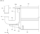
- the battery cell assembly may further include a first pipe connected to a first upper port on a lower side of the protruding part and configured to transfer the first fluid.
- the first pipe may include a first part extending downward from the first upper port of the upper cover plate, a second part extending from the first part in a direction crossing a direction in which the first part extends, and a third part extending upward from the second part.
- the second pipe may include a fourth part extending downward from the second upper port of the upper cover plate, a fifth part extending from the fourth part in a direction crossing a direction in which the fourth part extends, and a sixth part extending upward from the fifth part.
- the battery cell assembly may further include a second elastic pad provided between the fifth part of the second pipe and the second bottom support.
- the lower cover plate may further include a protruding part protruding from a side of the cell block.
- an upper end of the protruding part of the lower cover plate may be provided with a first lower port into which the second fluid is introduced and a second lower port from which the second fluid is discharged.
- the side cover plate may be coupled to the upper cover plate and the lower cover plate.
- the side cover plate may include a fastening flange configured to be fastened to an external support structure.
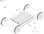
- a battery pack including a pack housing, and a battery cell assembly accommodated in the pack housing, and including a cell block with a plurality of battery cells and a case configured to accommodate the cell block, and the case includes an upper cover plate facing an upper side of the cell block and including a first cooling channel configured such that a first fluid flows therethrough, and a lower cover plate facing a lower side of the cell block, and including a venting hole and a second cooling channel configured such that a second fluid flows therethrough.
- the case may further include a side cover plate facing a lateral side of the cell block.
- the side cover plate may include a fastening flange configured to be fastened to a support structure on a bottom wall of the pack housing.
- the lower cover plate of the battery cell assembly may be spaced apart from the bottom wall of the pack housing with a first space interposed therebetween.
- the lower side of the cell block may be exposed toward the first space through the venting hole.
- the upper cover plate may further include a protruding part protruding from a side of the cell block.
- the battery cell assembly may further include a first pipe connected to a first upper port on a lower side of the protruding part and configured to transfer the first fluid supplied from the outside to the first cooling channel.
- the cell block 110 includes a plurality of battery cells 111.
- Each of the battery cells 111 is a basic unit of a lithium ion battery, i.e., a secondary battery.
- Each of the battery cells 111 may include an electrode assembly, an electrolyte, and a cell case.
- the electrode assembly provided in the cell case may include a positive electrode, a negative electrode, and a separator interposed between the positive electrode and the negative electrode.
- the electrode assembly may be a jelly-roll type electrode assembly or a stack type electrode assembly according to a form of assembly.
- the jelly roll type electrode assembly may include a structure in which a positive electrode, a negative electrode, and a separator interposed therebetween are wound together.
- the stack type electrode assembly may include a plurality of positive electrodes, a plurality of negative electrodes, and a plurality of separators interposed therebetween that are stacked sequentially.
- the positive electrodes may each include a positive electrode current collector and a positive electrode active material.
- the negative electrodes may each include a negative electrode current collector and a negative electrode active material.
- the plurality of battery cells 111 may be connected in series and/or in parallel.
- the plurality of battery cells 111 may be connected to each other in series.
- the plurality of battery cells 111 may be connected to each other in parallel.
- a set of two or more battery cells 111 connected in parallel is defined as a bank, one bank including two or more battery cells 111 connected in parallel and another bank including two or more battery cells 111 connected in parallel may be connected in series.
- Each of the battery cells 111 may be a pouch type battery cell, a cylindrical battery cell, or a prismatic battery cell.
- An electrode assembly of the pouch type battery cell is embedded in a pouch case including an aluminum laminate sheet.
- An electrode assembly of the cylindrical battery cell is embedded in a cylindrical metal can.
- An electrode assembly of the prismatic battery cell is embedded in a prismatic metal can.
- the plurality of battery cells 111 may be pouch type battery cells and be stacked in one battery cell assembly 100 in a first direction (an X-axis direction).
- the plurality of battery cells 111 in each battery cell assembly 100, may be pouch type battery cells whose length in the first direction (the X-axis direction) is less than a length thereof in a second direction (a Y-axis direction) and be stacked in the first direction (the X-axis direction).
- the cell block 110 When viewed from a plane, the cell block 110 may have a rectangular shape whose length in the first direction (the X-axis direction) is less than a length thereof in the second direction (the Y-axis direction).
- the cell block 110 may have two lateral sides (i.e., a first lateral side and a second lateral side) facing each other in the first direction (the X-axis direction), a front side and a rear side facing each other in the second direction (the Y-axis direction), and an upper side and a lower side facing each other in a vertical direction (a Z-axis direction).
- a bus bar frame on which bus bars are mounted may be disposed on each of the front and rear sides of the cell block 110.
- a plurality of bus bars may be mounted on the bus bar frame on the front side of the cell block 110, and a plurality of bus bars may be mounted on the bus bar frame on the rear side of the cell block 110.
- An end plate 170 may be disposed on each of the front and rear sides of the cell block 110.
- the end plate 170 on the front side of the cell block 110 may cover the bus bar frame on the front side of the cell block 110, and the end plate 170 on the rear side of the cell block 110 may cover the bus bar frame on the rear side of the cell block 110.
- a bus bar may be coupled to electrode leads of the battery cell 111.
- the bus bar may be coupled to the electrode leads of the battery cell 111 by welding.
- each bus bar may be an inter-bus bar coupled to electrode leads coupled to different battery cells 111 belonging to the cell block 110 to electrically connect the different battery cells 111.
- each bus bar may be a terminal bus bar for electrically coupling the battery cell assembly 100 to another battery cell assembly 100 or another electrical device.
- the battery cell assembly 100 may include a single cell block 110.
- the battery cell assembly 100 may include a cell block array with a plurality of cell blocks 110 arranged in the second direction (the Y-axis direction).
- the battery cell assembly 100 may include two cell blocks 110 arranged in the second direction (the Y-axis direction).
- the battery cell assembly 100 may include a first cell block and a second cell block that are arranged in the case CA to be spaced apart from each other in the second direction (the Y-axis direction) and electrically connected to each other.
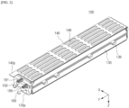
- An upper cover plate 120 may at least partially cover the upper side of the cell block 110.
- the upper cover plate 120 may be coupled to upper ends of two side cover plates 130 on both sides of the cell block 110.
- one lateral part of the upper cover plate 120 may be coupled to the upper end of one of the side cover plates 130 by welding, and another lateral part thereof may be coupled to the upper end of the other side cover plate 130 by welding.
- the upper cover plate 120 faces the upper side of the cell block 110.
- the upper cover plate 120 may be attached to the upper side of the cell block 110 and be thermally coupled to the cell block 110.
- the upper cover plate 120 may be attached to the upper side of the cell block 110 through a thermally conductive adhesive layer interposed between the upper cover plate 120 and the upper side of the cell block 110.
- the thermally conductive adhesive layer may include a thermal interface material (TIM).
- the upper cover plate 120 includes a first cooling channel 123 configured to allow a first fluid to flow therethrough and be configured to cool the cell block 110.
- the first cooling channel 123 defines a passage for the first fluid.
- the first cooling channel 123 may have a single path extending from an inlet thereof to an outlet thereof. While the first fluid flows along the first cooling channel 123, the battery cell assembly 100 may be cooled.
- the upper cover plate 120 may be manufactured by bonding two plates, and the first cooling channel 123 may include a space defined between the two plates. That is, the cooling channel 123 may be located inside of the upper cover plate 120.
- the first fluid may include coolant or a refrigerant. The first fluid can thus be a cooling fluid.
- the upper cover plate 120 may include a first upper port 1231 to which a first pipe 150 is connected and a second upper port 1233 to which a second pipe 160 is connected.
- One of the first upper port 1231 and the second upper port 1233 of the upper cover plate 120 may include the inlet of the first cooling channel 123 into which the first fluid is introduced, and the other may include the outlet of the first cooling channel 123 from which the first fluid is discharged.
- both the first upper port 1231 and the second upper port 1233 of the upper cover plate 120 are located at the same side of the upper cover plate 120. That is, the inlet and the outlet of the first fluid are located at the same side of the upper cover plate 120.
- the first upper port 1231 and the second upper port 1233 of the upper cover plate 120 may be located at different sides of the upper cover plate 120, such as at the opposite sides of the upper cover plate 120 in the longitudinal direction of the upper cover plate 120 (that is opposite side in the direction of the y-axis). That is, the inlet and the outlet of the first fluid may be located at different sides of the upper cover plate 120, such as at opposite sides of the upper cover plate 120.
- the first upper port 1231 of the upper cover plate 120 may include the inlet of the first cooling channel 123, and the second upper port 1233 thereof may include the outlet of the first cooling channel 123.
- the first fluid provided from an external fluid supply CS may be transferred to an inlet 159 of the first pipe 150 through a flow path of a first transfer pipe 301, and may flow along a flow path 157 of the first pipe 150, the first upper port 1231 of the upper cover plate 120, the first cooling channel 123, the second upper port 1233 of the upper cover plate 120, and a flow path 167 of the second pipe 160. Thereafter, the first fluid may be discharged to a second transfer pipe 302 through an outlet 169 of the second pipe 160 and recovered to the external fluid supply CS through the second transfer pipe 302.
- the upper cover plate 120 may include a protruding part 120p protruding from the cell block 110 to one side.
- the protruding part 120p of the upper cover plate 120 may protrude from the front side of the cell block 110 in the second direction (the Y-axis direction).
- Both the first upper port 1231 and the second upper port 1233 of the upper cover plate 120 may be provided on the protruding part 120p of the upper cover plate 120.
- Both the first upper port 1231 and the second upper port 1233 of the upper cover plate 120 may be provided on a lower side of the protruding part 120p of the upper cover plate 120.
- each of the side cover plates 130 may include one or more fastening flanges 139 protruding in the first direction (the X-axis direction).
- the fastening flange 139 may be provided with a fastening hole through which a fastening member such as a bolt passes.
- the fastening flange 139 may be fastened and supported on a support structure of the pack housing 501 by a fastening member such as a bolt.
- the lower cover plate 140 is disposed to face the lower side of the cell block 110.
- the lower cover plate 140 may at least partially cover the lower side of the cell block 110.
- the lower cover plate 140 may be coupled to lower ends of the two side cover plates 130 on both sides of the cell block 110.
- one lateral part of the lower cover plate 140 may be coupled to the lower end of one of the side cover plates 130 by welding, and another lateral part thereof may be coupled to the lower end of the other side cover plate 130 by welding.
- the lower cover plate 140, the upper cover plate 120, and optionally the side cover plates 130 may form a case CA surrounding four surfaces (e.g., the upper side, the lower side, the first lateral side, and the second lateral side) of the cell block 110.
- the lower cover plate 140 may be attached to the lower side of the cell block 110 and be thermally coupled to the cell block 110.
- the lower cover plate 140 may be attached to the lower side of the cell block 110 through a thermally conductive adhesive layer interposed between the lower cover plate 140 and the lower side of the cell block 110.
- the thermally conductive adhesive layer may include the TIM.
Landscapes
- Chemical & Material Sciences (AREA)
- Chemical Kinetics & Catalysis (AREA)
- Electrochemistry (AREA)
- General Chemical & Material Sciences (AREA)
- Engineering & Computer Science (AREA)
- Manufacturing & Machinery (AREA)
- Aviation & Aerospace Engineering (AREA)
- Battery Mounting, Suspending (AREA)
- Secondary Cells (AREA)
- Gas Exhaust Devices For Batteries (AREA)
Applications Claiming Priority (1)
| Application Number | Priority Date | Filing Date | Title |
|---|---|---|---|
| KR20230122363 | 2023-09-14 |
Publications (2)
| Publication Number | Publication Date |
|---|---|
| EP4525143A1 true EP4525143A1 (de) | 2025-03-19 |
| EP4525143B1 EP4525143B1 (de) | 2026-02-04 |
Family
ID=92301117
Family Applications (1)
| Application Number | Title | Priority Date | Filing Date |
|---|---|---|---|
| EP24193920.6A Active EP4525143B1 (de) | 2023-09-14 | 2024-08-09 | Batteriezellenanordnung und batteriepack damit |
Country Status (7)
| Country | Link |
|---|---|
| EP (1) | EP4525143B1 (de) |
| JP (1) | JP2025539082A (de) |
| KR (1) | KR20250039918A (de) |
| CN (1) | CN120202581A (de) |
| ES (1) | ES3063836T3 (de) |
| PL (1) | PL4525143T3 (de) |
| WO (1) | WO2025058389A1 (de) |
Citations (8)
| Publication number | Priority date | Publication date | Assignee | Title |
|---|---|---|---|---|
| KR102218473B1 (ko) | 2018-01-19 | 2021-02-23 | 한온시스템 주식회사 | 일체형 공기 통풍구들을 가진 배터리 냉각판 |
| CN113994524A (zh) * | 2019-04-15 | 2022-01-28 | 罗伯特·博世有限公司 | 具有热管理系统的电池包 |
| WO2022223892A1 (fr) * | 2021-04-20 | 2022-10-27 | Psa Automobiles Sa | Systeme de batterie de stockage d'energie electrique comprenant un systeme de securite de degazage |
| US20220361367A1 (en) * | 2021-05-04 | 2022-11-10 | Rimac Automobiles Ltd. | Cold plate assembly |
| KR20220169831A (ko) | 2021-06-21 | 2022-12-28 | 주식회사 엘지에너지솔루션 | 가스 배출 경로를 개선한 배터리 팩 |
| KR20230028037A (ko) | 2021-08-20 | 2023-02-28 | 현대모비스 주식회사 | 고전압 배터리용 냉각장치 |
| EP4199215A1 (de) * | 2021-03-23 | 2023-06-21 | LG Energy Solution, Ltd. | Batteriemodul mit struktur zur verhinderung von wärmeableitung in batteriezellen unter verwendung von kühlmittel und batteriepack damit |
| KR20230104442A (ko) | 2021-12-31 | 2023-07-10 | 서진산업 주식회사 | 배터리 냉각기능을 향상시킨 전기차량용 배터리 케이스 |
Family Cites Families (5)
| Publication number | Priority date | Publication date | Assignee | Title |
|---|---|---|---|---|
| JP5343048B2 (ja) * | 2010-07-29 | 2013-11-13 | 日立ビークルエナジー株式会社 | 蓄電モジュールおよび蓄電装置 |
| JP5777734B2 (ja) * | 2011-02-22 | 2015-09-09 | エルジー ケム. エルティーディ. | 冷却効率の改善された冷却部材及びそれを用いたバッテリーモジュール |
| KR102256104B1 (ko) * | 2017-04-07 | 2021-06-03 | 주식회사 엘지에너지솔루션 | 배터리 모듈, 이러한 배터리 모듈을 포함하는 배터리 팩 및 이러한 배터리 팩을 포함하는 자동차 |
| JP7049892B2 (ja) * | 2018-04-04 | 2022-04-07 | 昭和電工株式会社 | 組電池用冷却兼加熱装置 |
| KR102690299B1 (ko) * | 2020-06-29 | 2024-08-01 | 주식회사 엘지에너지솔루션 | 방열부재를 포함하는 전지모듈 및 상기 방열부재의 제조방법 |
-
2024
- 2024-08-09 ES ES24193920T patent/ES3063836T3/es active Active
- 2024-08-09 PL PL24193920.6T patent/PL4525143T3/pl unknown
- 2024-08-09 EP EP24193920.6A patent/EP4525143B1/de active Active
- 2024-09-11 WO PCT/KR2024/013779 patent/WO2025058389A1/ko active Pending
- 2024-09-11 CN CN202480004715.6A patent/CN120202581A/zh active Pending
- 2024-09-11 JP JP2025527116A patent/JP2025539082A/ja active Pending
- 2024-09-13 KR KR1020240125299A patent/KR20250039918A/ko active Pending
Patent Citations (9)
| Publication number | Priority date | Publication date | Assignee | Title |
|---|---|---|---|---|
| KR102218473B1 (ko) | 2018-01-19 | 2021-02-23 | 한온시스템 주식회사 | 일체형 공기 통풍구들을 가진 배터리 냉각판 |
| CN113994524A (zh) * | 2019-04-15 | 2022-01-28 | 罗伯特·博世有限公司 | 具有热管理系统的电池包 |
| EP4199215A1 (de) * | 2021-03-23 | 2023-06-21 | LG Energy Solution, Ltd. | Batteriemodul mit struktur zur verhinderung von wärmeableitung in batteriezellen unter verwendung von kühlmittel und batteriepack damit |
| WO2022223892A1 (fr) * | 2021-04-20 | 2022-10-27 | Psa Automobiles Sa | Systeme de batterie de stockage d'energie electrique comprenant un systeme de securite de degazage |
| US20220361367A1 (en) * | 2021-05-04 | 2022-11-10 | Rimac Automobiles Ltd. | Cold plate assembly |
| KR20220169831A (ko) | 2021-06-21 | 2022-12-28 | 주식회사 엘지에너지솔루션 | 가스 배출 경로를 개선한 배터리 팩 |
| CN116057768A (zh) * | 2021-06-21 | 2023-05-02 | 株式会社Lg新能源 | 具有改善的排气路径的电池组 |
| KR20230028037A (ko) | 2021-08-20 | 2023-02-28 | 현대모비스 주식회사 | 고전압 배터리용 냉각장치 |
| KR20230104442A (ko) | 2021-12-31 | 2023-07-10 | 서진산업 주식회사 | 배터리 냉각기능을 향상시킨 전기차량용 배터리 케이스 |
Also Published As
| Publication number | Publication date |
|---|---|
| CN120202581A (zh) | 2025-06-24 |
| KR20250039918A (ko) | 2025-03-21 |
| EP4525143B1 (de) | 2026-02-04 |
| WO2025058389A1 (ko) | 2025-03-20 |
| PL4525143T3 (pl) | 2026-04-20 |
| ES3063836T3 (en) | 2026-04-20 |
| JP2025539082A (ja) | 2025-12-03 |
Similar Documents
| Publication | Publication Date | Title |
|---|---|---|
| EP4583284A1 (de) | Batteriemodul und batteriepack damit | |
| EP4525143B1 (de) | Batteriezellenanordnung und batteriepack damit | |
| EP4376189A1 (de) | Batteriepack und darin enthaltener zellenblock sowie fahrzeug damit | |
| EP4614680A1 (de) | Batteriezellenanordnung und batteriepack damit | |
| EP4611128A1 (de) | Batteriezellenanordnung und batteriepack damit | |
| EP4614679A1 (de) | Batterieanordnung und batteriepack damit | |
| US20250346126A1 (en) | Battery pack including battery assembly, and electric vehicle including battery pack | |
| EP4614702A1 (de) | Batteriepack | |
| KR102872687B1 (ko) | 배터리 팩 | |
| EP4586368A1 (de) | Batteriezellenanordnung und batteriepack damit | |
| KR102886360B1 (ko) | 배터리 조립체를 포함하는 배터리 팩 및 배터리 팩을 포함하는 전기 자동차 | |
| EP4664646A1 (de) | Batterieanordnung | |
| EP4621962A1 (de) | Batteriepack | |
| KR20250036471A (ko) | 배터리 조립체 및 이를 포함하는 배터리 팩 | |
| EP4712235A1 (de) | Batterieanordnung und batteriepack damit | |
| KR20250028976A (ko) | 배터리 셀 어셈블리 및 이를 포함하는 배터리 팩 | |
| EP4708461A1 (de) | Batteriepack | |
| CN121039869A (zh) | 电池组 | |
| CN121153161A (zh) | 电池组和包括该电池组的车辆 |
Legal Events
| Date | Code | Title | Description |
|---|---|---|---|
| PUAI | Public reference made under article 153(3) epc to a published international application that has entered the european phase |
Free format text: ORIGINAL CODE: 0009012 |
|
| STAA | Information on the status of an ep patent application or granted ep patent |
Free format text: STATUS: REQUEST FOR EXAMINATION WAS MADE |
|
| STAA | Information on the status of an ep patent application or granted ep patent |
Free format text: STATUS: EXAMINATION IS IN PROGRESS |
|
| 17P | Request for examination filed |
Effective date: 20240809 |
|
| AK | Designated contracting states |
Kind code of ref document: A1 Designated state(s): AL AT BE BG CH CY CZ DE DK EE ES FI FR GB GR HR HU IE IS IT LI LT LU LV MC ME MK MT NL NO PL PT RO RS SE SI SK SM TR |
|
| RIN1 | Information on inventor provided before grant (corrected) |
Inventor name: KIM, JAE WOOK Inventor name: KIM, MIN SUNG Inventor name: KIM, GWAN WOO Inventor name: JANG, SUNG HWAN |
|
| 17Q | First examination report despatched |
Effective date: 20250304 |
|
| GRAP | Despatch of communication of intention to grant a patent |
Free format text: ORIGINAL CODE: EPIDOSNIGR1 |
|
| STAA | Information on the status of an ep patent application or granted ep patent |
Free format text: STATUS: GRANT OF PATENT IS INTENDED |
|
| INTG | Intention to grant announced |
Effective date: 20251112 |
|
| GRAS | Grant fee paid |
Free format text: ORIGINAL CODE: EPIDOSNIGR3 |
|
| GRAA | (expected) grant |
Free format text: ORIGINAL CODE: 0009210 |
|
| STAA | Information on the status of an ep patent application or granted ep patent |
Free format text: STATUS: THE PATENT HAS BEEN GRANTED |
|
| P01 | Opt-out of the competence of the unified patent court (upc) registered |
Free format text: CASE NUMBER: UPC_APP_0015386_4525143/2025 Effective date: 20251201 |
|
| AK | Designated contracting states |
Kind code of ref document: B1 Designated state(s): AL AT BE BG CH CY CZ DE DK EE ES FI FR GB GR HR HU IE IS IT LI LT LU LV MC ME MK MT NL NO PL PT RO RS SE SI SK SM TR |
|
| REG | Reference to a national code |
Ref country code: CH Ref legal event code: F10 Free format text: ST27 STATUS EVENT CODE: U-0-0-F10-F00 (AS PROVIDED BY THE NATIONAL OFFICE) Effective date: 20260204 Ref country code: GB Ref legal event code: FG4D |
|
| REG | Reference to a national code |
Ref country code: DE Ref legal event code: R096 Ref document number: 602024002395 Country of ref document: DE |
|
| REG | Reference to a national code |
Ref country code: IE Ref legal event code: FG4D |
|
| REG | Reference to a national code |
Ref country code: NL Ref legal event code: FP |
|
| REG | Reference to a national code |
Ref country code: ES Ref legal event code: FG2A Ref document number: 3063836 Country of ref document: ES Kind code of ref document: T3 Effective date: 20260420 |