EP4525176A1 - Batteriemodul, batteriepack damit und fahrzeug damit - Google Patents
Batteriemodul, batteriepack damit und fahrzeug damit Download PDFInfo
- Publication number
- EP4525176A1 EP4525176A1 EP23921506.4A EP23921506A EP4525176A1 EP 4525176 A1 EP4525176 A1 EP 4525176A1 EP 23921506 A EP23921506 A EP 23921506A EP 4525176 A1 EP4525176 A1 EP 4525176A1
- Authority
- EP
- European Patent Office
- Prior art keywords
- flame
- pouch
- internal pouch
- battery module
- battery cell
- Prior art date
- Legal status (The legal status is an assumption and is not a legal conclusion. Google has not performed a legal analysis and makes no representation as to the accuracy of the status listed.)
- Pending
Links
Images


Classifications
-
- H—ELECTRICITY
- H01—ELECTRIC ELEMENTS
- H01M—PROCESSES OR MEANS, e.g. BATTERIES, FOR THE DIRECT CONVERSION OF CHEMICAL ENERGY INTO ELECTRICAL ENERGY
- H01M50/00—Constructional details or processes of manufacture of the non-active parts of electrochemical cells other than fuel cells, e.g. hybrid cells
- H01M50/20—Mountings; Secondary casings or frames; Racks, modules or packs; Suspension devices; Shock absorbers; Transport or carrying devices; Holders
- H01M50/249—Mountings; Secondary casings or frames; Racks, modules or packs; Suspension devices; Shock absorbers; Transport or carrying devices; Holders specially adapted for aircraft or vehicles, e.g. cars or trains
-
- H—ELECTRICITY
- H01—ELECTRIC ELEMENTS
- H01M—PROCESSES OR MEANS, e.g. BATTERIES, FOR THE DIRECT CONVERSION OF CHEMICAL ENERGY INTO ELECTRICAL ENERGY
- H01M10/00—Secondary cells; Manufacture thereof
- H01M10/42—Methods or arrangements for servicing or maintenance of secondary cells or secondary half-cells
-
- H—ELECTRICITY
- H01—ELECTRIC ELEMENTS
- H01M—PROCESSES OR MEANS, e.g. BATTERIES, FOR THE DIRECT CONVERSION OF CHEMICAL ENERGY INTO ELECTRICAL ENERGY
- H01M50/00—Constructional details or processes of manufacture of the non-active parts of electrochemical cells other than fuel cells, e.g. hybrid cells
- H01M50/20—Mountings; Secondary casings or frames; Racks, modules or packs; Suspension devices; Shock absorbers; Transport or carrying devices; Holders
- H01M50/204—Racks, modules or packs for multiple batteries or multiple cells
-
- H—ELECTRICITY
- H01—ELECTRIC ELEMENTS
- H01M—PROCESSES OR MEANS, e.g. BATTERIES, FOR THE DIRECT CONVERSION OF CHEMICAL ENERGY INTO ELECTRICAL ENERGY
- H01M50/00—Constructional details or processes of manufacture of the non-active parts of electrochemical cells other than fuel cells, e.g. hybrid cells
- H01M50/20—Mountings; Secondary casings or frames; Racks, modules or packs; Suspension devices; Shock absorbers; Transport or carrying devices; Holders
- H01M50/204—Racks, modules or packs for multiple batteries or multiple cells
- H01M50/207—Racks, modules or packs for multiple batteries or multiple cells characterised by their shape
- H01M50/211—Racks, modules or packs for multiple batteries or multiple cells characterised by their shape adapted for pouch cells
-
- H—ELECTRICITY
- H01—ELECTRIC ELEMENTS
- H01M—PROCESSES OR MEANS, e.g. BATTERIES, FOR THE DIRECT CONVERSION OF CHEMICAL ENERGY INTO ELECTRICAL ENERGY
- H01M50/00—Constructional details or processes of manufacture of the non-active parts of electrochemical cells other than fuel cells, e.g. hybrid cells
- H01M50/30—Arrangements for facilitating escape of gases
- H01M50/35—Gas exhaust passages comprising elongated, tortuous or labyrinth-shaped exhaust passages
- H01M50/367—Internal gas exhaust passages forming part of the battery cover or case; Double cover vent systems
-
- H—ELECTRICITY
- H01—ELECTRIC ELEMENTS
- H01M—PROCESSES OR MEANS, e.g. BATTERIES, FOR THE DIRECT CONVERSION OF CHEMICAL ENERGY INTO ELECTRICAL ENERGY
- H01M50/00—Constructional details or processes of manufacture of the non-active parts of electrochemical cells other than fuel cells, e.g. hybrid cells
- H01M50/30—Arrangements for facilitating escape of gases
- H01M50/383—Flame arresting or ignition-preventing means
-
- H—ELECTRICITY
- H01—ELECTRIC ELEMENTS
- H01M—PROCESSES OR MEANS, e.g. BATTERIES, FOR THE DIRECT CONVERSION OF CHEMICAL ENERGY INTO ELECTRICAL ENERGY
- H01M2220/00—Batteries for particular applications
- H01M2220/20—Batteries in motive systems, e.g. vehicle, ship, plane
-
- Y—GENERAL TAGGING OF NEW TECHNOLOGICAL DEVELOPMENTS; GENERAL TAGGING OF CROSS-SECTIONAL TECHNOLOGIES SPANNING OVER SEVERAL SECTIONS OF THE IPC; TECHNICAL SUBJECTS COVERED BY FORMER USPC CROSS-REFERENCE ART COLLECTIONS [XRACs] AND DIGESTS
- Y02—TECHNOLOGIES OR APPLICATIONS FOR MITIGATION OR ADAPTATION AGAINST CLIMATE CHANGE
- Y02E—REDUCTION OF GREENHOUSE GAS [GHG] EMISSIONS, RELATED TO ENERGY GENERATION, TRANSMISSION OR DISTRIBUTION
- Y02E60/00—Enabling technologies; Technologies with a potential or indirect contribution to GHG emissions mitigation
- Y02E60/10—Energy storage using batteries
Definitions
- lithium secondary batteries are widely used because they have advantages of flexible charging and discharging due to almost no memory effect, a very low self-discharge rate, and a high energy density, compared to nickel-based secondary batteries.
- the lithium secondary batteries generally use lithium-based oxides and carbon materials as positive and negative electrode active materials, respectively.
- the lithium secondary batteries include an electrode assembly in which the positive and negative electrode plates, which are respectively coated with the positive and negative electrode active materials, are disposed with a separator therebetween, and an exterior case, i.e., a battery case, that seals and stores the electrode assembly with an electrolyte.
- Lithium secondary batteries are configured to have a positive electrode, a negative electrode, a separator interposed therebetween, and an electrolyte, and may be classified to lithium-ion batteries (LIBs) and polymer lithium-ion batteries (PLIBs) depending on the materials used for the positive electrode active material and negative electrode active material.
- LIBs lithium-ion batteries
- PLIBs polymer lithium-ion batteries
- the electrodes of the lithium secondary batteries are formed by applying a positive electrode or negative electrode active material to a collector such as an aluminum or copper sheet, mesh, film, or foil and then drying it.
- various types of secondary batteries may have a housing capable of protecting the battery cell, and may be used as a module including a plurality of battery cells.
- FIG. 1 is a diagram schematically illustrating the arrangement of a plurality of battery cells in a conventional battery module including the plurality of battery cells.
- a battery module case is omitted.
- the flame and gas may propagate in various directions, for example, toward the top or sides of the battery cell (see arrows in FIG. 1 ).
- the present disclosure has been designed to solve the problems of the related art, and therefore the present disclosure is directed to providing a battery module capable of discharging flame or gas generated from any battery cell in a predetermined direction to prevent propagation thereof to neighboring battery cells, thereby securing the stability of the battery module, and a battery pack and a vehicle including the same.
- a battery module including: a battery cell stack in which a plurality of battery cells is stacked; and a case configured to store the battery cell stack therein, wherein the battery cell includes a flame gas guide portion configured to guide flame or gas generated from the battery cell in one direction.
- the battery cell may be a pouch-type battery cell
- the pouch-type battery cell may include: an internal pouch configured to store a positive electrode plate, a separator, a negative electrode plate, and an electrolyte therein and have a plurality of edges formed thereon; a positive electrode lead connected to the positive electrode plate; a negative electrode lead connected to the negative electrode plate; a flame-retardant member configured to surround only a portion of the internal pouch; and an external pouch configured to surround the internal pouch and the flame-retardant member, and the flame gas guide portion may be formed in a portion of the internal pouch that is not surrounded by the flame-retardant member.
- the positive electrode lead may protrude from the inside of the internal pouch to the outside through one of the plurality of edges of the internal pouch
- the negative electrode lead may protrude from the inside of the internal pouch to the outside through the same edge as the edge where the positive electrode lead is located, among the plurality of edges of the internal pouch.
- the flame-retardant member may be configured to surround the remaining edges of the plurality of edges of the internal pouch, excluding the edge where the positive electrode lead and the negative electrode lead are located.
- the internal pouch may be formed in a square shape, and the positive electrode lead and the negative electrode lead may protrude from the inside of the internal pouch to the outside through a first edge of four edges of the internal pouch, and the flame gas guide portion may be formed on the first edge.
- the internal pouch may be formed in a rectangle including a long-side edge and a short-side edge, and the first edge may be the long-side edge.
- the flame-retardant member may be made of mica or glass fiber.
- the battery cell may be a pouch-type battery cell
- the pouch-type battery cell may include: an internal pouch configured to store a positive electrode plate, a separator, a negative electrode plate, and an electrolyte therein and have a plurality of edges formed thereon; a positive electrode lead connected to the positive electrode plate; a negative electrode lead connected to the negative electrode plate; a flame-retardant member configured to surround only a portion of the internal pouch; and an external cover configured to surround the internal pouch and the flame-retardant member, and the flame gas guide portion may be formed in a portion of the internal pouch that is not surrounded by the flame-retardant member.
- the flame-retardant member may be made of iron or stainless steel (SUS (Steel Use Stainless)).
- an outlet may be formed in a portion of the case where the flame gas guide portion is located such that the flame or gas guided through the flame gas guide portion is discharged to the outside of the case.
- the case may include an upper case, a lower case, and a side case, and the outlet may be formed on at least one of the upper case and the side case.
- a battery pack including the battery module described above, and a vehicle including the battery module.
- Embodiments of the present disclosure have the effect of discharging flame or gas generated from any battery cell in a predetermined direction to prevent propagation thereof to neighboring battery cells, thereby securing the stability of the battery module.
- Couple or "connect” used in this specification refers to the case where one member is indirectly coupled or connected to another member through a connection member, as well as the case where one member is directly coupled or connected to another member.
- FIG. 2 is a diagram illustrating an internal pouch in a battery cell according to an embodiment of the present disclosure
- FIG. 3 is a diagram illustrating the internal pouch in FIG. 2 surrounded by a flame-retardant member and an external pouch
- FIG. 4 is a diagram illustrating a battery cell according to another embodiment in relation to FIG. 2
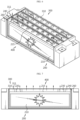
- FIG. 5 is a perspective view of the battery cell in FIG. 4 separated from a case of the battery module
- FIG. 6 is a combined perspective view of FIG. 5 , which illustrates the interior
- FIG. 7 is a cross-sectional view seen from the front in FIG. 6 .
- the battery cell stack 100 may be configured such that a plurality of battery cells 200 is stacked (see FIG. 5 ).
- the battery cell 200 includes a flame gas guide portion 400 for guiding the flame or gas generated from the battery cell 200 in one direction.
- the flame gas guide portion 400 will be described in detail later.
- the battery cell 200 may have various structures, and the plurality of battery cells 200 may be stacked in various ways.
- the battery cell 200 may be configured in a structure in which a plurality of unit cells, in which a positive electrode plate, a separator, and a negative electrode plate are arranged in sequence, or a plurality of bi-cells, in which a positive electrode plate, a separator, a negative electrode plate, a separator, a positive electrode plate, a separator, and a negative electrode plate are arranged in sequence, is stacked according to the battery capacity.
- the battery cell 200 may have an electrode lead.
- the electrode lead is a kind of terminal that is exposed to the outside and connected to an external device, and may be made of a conductive material.
- the electrode lead may include a positive electrode lead 220 and a negative electrode lead 230.
- the battery cell 200 may include various types and, for example, may be configured as a pouch-type battery cell 200.
- the pouch-type battery cell 200 may be configured to include an internal pouch 210, a positive electrode lead 220, a negative electrode lead 230, a flame-retardant member 240, and an external pouch 250.
- the positive electrode lead 220 is connected to the positive electrode plate 211, and the negative electrode lead 230 is connected to the negative electrode plate 213.
- the positive electrode lead 220 and the negative electrode lead 230 protrude from the inside of the internal pouch 210 to the outside.
- the positive electrode lead 220 and the negative electrode lead 230 may be positioned to face in the same direction.
- the positive electrode lead 220 may protrude from the inside of the internal pouch 210 to the outside through one of the plurality of edges of the internal pouch 210.
- the negative electrode lead 230 may protrude from the inside of the internal pouch 210 to the outside through the same edge as the edge where the positive electrode lead 220 is located, among the plurality of edges of the internal pouch 210.
- the positive electrode lead 220 and the negative electrode lead 230 may protrude from the inside of the internal pouch 210 to the outside through the same edge among the plurality of edges of the internal pouch 210.
- the flame-retardant member 240 may be configured to surround only a portion of the internal pouch 210.
- the flame-retardant member 240 may be configured to surround the edges of the internal pouch 210, excluding the edge where both the positive electrode lead 220 and the negative electrode lead 230 are located.
- the flame-retardant member 240 is configured to surround both sides and the bottom of the internal pouch 210, excluding the top of the internal pouch 210. That is, there is no flame-retardant member 240 only at the top of the internal pouch 210.
- the flame-retardant member 240 may be made of various materials, such that mica or glass fiber, but is not limited thereto.
- a flame gas guide portion 400 is formed in a portion of the internal pouch 210 that is not surrounded by the flame-retardant member 240.
- the flame gas guide portion 400 guides flame or gas to be discharged to the outside of the internal pouch 210, and for example, the flame gas guide portion 400 is formed at the top of the internal pouch 210 in FIG. 3 .
- the flame or gas is unable to be discharged to the outside through the portions surrounded by the flame-retardant member 240, but is able to be discharged through the top of the internal pouch 210 to which the flame-retardant member 240 is not provided.
- the flame or gas is guided to the flame gas guide portion 400 at the top of the internal pouch 210 not provided with the flame-retardant member 240.
- the internal pouch 210 may have various shapes, and for example, may be formed in a square as shown in FIG. 3 .
- the positive electrode lead 220 and the negative electrode lead 230 protrude from the inside of the internal pouch 210 to the outside through a first edge 215 (the upper edge of the internal pouch 210 in FIGS. 2 and 3 ) among the four edges of the internal pouch 210.
- the flame gas guide portion 400 is formed at the top of the internal pouch 210 not provided with the flame-retardant member 240, that is, at the first edge 215.
- the first edge 215 may be a long-side edge.
- the external pouch 250 is configured to surround the internal pouch 210 and the flame-retardant member 240.
- the external pouch 250 may be formed of the same material and in the same shape as the internal pouch 210.
- the external pouch 250 may completely seal the internal pouch 210, or may be formed such that only the top of the internal pouch 210, having the flame gas guide portion 400 formed, is open.
- FIGS. 4 to 7 other embodiments in relation to FIGS. 2 and 3 are shown in FIGS. 4 to 7 .
- FIGS. 4 to 7 are different from that in FIGS. 2 and 3 in that an external cover 260 is provided instead of the external pouch 250 in FIGS. 2 and 3 .
- an external cover 260 is provided instead of the external pouch 250 in FIGS. 2 and 3 .
- the configuration of the internal pouch 210 and the arrangement of the positive electrode lead 220 and the negative electrode lead 230 in the same direction are the same as those in the embodiment in FIGS. 2 and 3 described above.
- the flame-retardant member 240 may be made of mica or glass fiber, it may also be made of iron or stainless steel (SUS (Steel Use Stainless)).
- the external cover 260 is provided to surround the internal pouch 210 and the flame-retardant member 240.
- the external pouch 250 may be formed of the same material as the internal pouch 210, whereas the external cover 260 may be formed of a different material from the internal pouch 210.
- the battery cell stack 100 may have a plurality of cartridges (not shown) that accommodate the battery cells 200.
- Each cartridge (not shown) may be manufactured by plastic injection molding, and a plurality of cartridges (not shown) having a storage portion capable of storing the battery cells 200 may be stacked.
- a cartridge assembly in which a plurality of cartridges (not shown) is stacked may have connector elements or terminal elements.
- the connector elements may include, for example, various types of electrical connection components or members for connection with a BMS (Battery Management System) (not shown) capable of providing data on the voltage or temperature of the battery cell 200 or the like.
- BMS Battery Management System
- the terminal elements are main terminals connected to the battery cell 200 and include a positive electrode terminal and a negative electrode terminal, and the terminal element may have a terminal bolt to be electrically connected to the outside structure.
- the battery cell 200 may have various shapes.
- the battery cell stack 100 is stored in the case 300.
- the case 300 surrounds the battery cells 200 to protect the battery cells 200 from external vibration or impact.
- the case 300 may be formed in a shape corresponding to the shape of the battery cell stack 100.
- the case 300 may also be configured in a hexahedral shape corresponding thereto.
- the case 300 may be manufactured, for example, by bending a metal plate, and as a result, the case 300 may be manufactured as an integrated piece. If the case 300 is manufactured as an integrated piece, the coupling process may be simplified and easy. Alternatively, the case 300 may be configured as a separate type and coupled by welding or the like. However, the material of the case 300 is not limited to metal.
- a portion of the case 300 where the flame gas guide portion 400 is located may have an outlet 311 formed through which the flame or gas guided by the flame gas guide portion 400 exit to the outside.
- the case 300 may include an upper case 310, a lower case 320, and a side case 330, and the outlet 311 may be formed on the upper case 310, may be formed on the side case 330, or may be formed on both the upper case 310 and the side case 330.
- outlet 311 is formed on the upper case 310 in FIGS. 5 to 7 , the present invention is not limited thereto, and the location of the outlet 311 may vary.
- FIGS. 4 to 7 illustrate an embodiment in which the external cover 260 is stored in the case 300
- the configuration of the discharge of flame or gas through the outlet 311 may be also applicable to the embodiment in FIGS. 2 and 3 in which the external pouch 250 is stored in the case 300.
- the positive electrode lead 220 and the negative electrode lead 230 protrude from the inside of the internal pouch 210 to the outside through the same edge among a plurality of edges of the internal pouch 210.
- the flame-retardant member 240 is configured to surround both sides and the bottom of the internal pouch 210, excluding the top of the internal pouch 210, that is, to surround the remaining edges, excluding the edge where both the positive electrode lead 220 and the negative electrode lead 230 are located, among the plurality of edges of the internal pouch 210.
- a flame gas guide portion 400 is formed in a portion of the internal pouch 210 that is not surrounded by the flame-retardant member 240, for example, at the top of the internal pouch 210 in FIG. 3 .
- the external pouch 250 is configured to surround the internal pouch 210 and the flame-retardant member 240.
- the external pouch 250 is made of the same material and has the same shape as the internal pouch 210.
- the flame or gas is unable to be discharged through the portions surrounded by the flame-retardant member 240, but is able to be discharged to the outside of the internal pouch 210 through the top of the internal pouch 210 not provided with the flame-retardant member 240, that is, through the flame gas guide portion 400.
- the flame or gas is guided to the top of the internal pouch 210 not provided with the flame-retardant member 240.
- an external cover 260 is provided instead of the external pouch 250.
- an outlet 311 is formed on the case 300, for example, the upper case 310 in common in both the embodiment in FIGS. 2 and 3 and the embodiment in FIGS. 4 to 7 , and the flame or gas generated in the battery cell 200 moves through the top of the internal pouch 210 not provided with the flame-retardant member 240 and then exit to the outside of the case 300 through the outlet 311 of the upper case 310 (see arrows in FIGS. 6 and 7 ).
- the flame or gas may be discharged to the outside of the case 300 through the flame gas guide portion 400 of the battery cell 200 and the outlet 311 of the upper case 310 while not moving to the sides of the battery cell 200, thereby preventing flame or gas from spreading to other adjacent battery cells 200.
- a battery pack (not shown) according to an embodiment of the present disclosure may include one or more battery modules 10 according to an embodiment of the present disclosure described above.
- the battery pack may further include, in addition to the battery module 10, a pack case (not shown) for storing the battery module 10, and various devices for controlling charging and discharging of the battery module 10, such as a BMS, a current sensor, a fuse, or the like.
- a vehicle (not shown) may include the aforementioned battery module 10 or battery pack (not shown), and the battery pack (not shown) may include the battery module 10.
- the battery module 10 according to an embodiment of the present disclosure may be applied to the vehicle (not shown), for example, a predetermined vehicle (not shown) that is configured to use electricity, such as an electric vehicle or a hybrid vehicle.
- the present disclosure relates to a battery module, and a battery pack and a vehicle including them, and particularly, is available to industries related to secondary batteries.
Landscapes
- Chemical & Material Sciences (AREA)
- Chemical Kinetics & Catalysis (AREA)
- Electrochemistry (AREA)
- General Chemical & Material Sciences (AREA)
- Engineering & Computer Science (AREA)
- Aviation & Aerospace Engineering (AREA)
- Manufacturing & Machinery (AREA)
- Battery Mounting, Suspending (AREA)
- Gas Exhaust Devices For Batteries (AREA)
Applications Claiming Priority (2)
| Application Number | Priority Date | Filing Date | Title |
|---|---|---|---|
| KR1020230015619A KR20240123096A (ko) | 2023-02-06 | 2023-02-06 | 배터리 모듈, 이를 포함하는 배터리 팩 및 자동차 |
| PCT/KR2023/021254 WO2024167134A1 (ko) | 2023-02-06 | 2023-12-21 | 배터리 모듈, 이를 포함하는 배터리 팩 및 자동차 |
Publications (2)
| Publication Number | Publication Date |
|---|---|
| EP4525176A1 true EP4525176A1 (de) | 2025-03-19 |
| EP4525176A4 EP4525176A4 (de) | 2026-01-21 |
Family
ID=92263165
Family Applications (1)
| Application Number | Title | Priority Date | Filing Date |
|---|---|---|---|
| EP23921506.4A Pending EP4525176A4 (de) | 2023-02-06 | 2023-12-21 | Batteriemodul, batteriepack damit und fahrzeug damit |
Country Status (5)
| Country | Link |
|---|---|
| EP (1) | EP4525176A4 (de) |
| JP (1) | JP2025528120A (de) |
| KR (1) | KR20240123096A (de) |
| CN (1) | CN118901166A (de) |
| WO (1) | WO2024167134A1 (de) |
Family Cites Families (13)
| Publication number | Priority date | Publication date | Assignee | Title |
|---|---|---|---|---|
| KR100944987B1 (ko) * | 2007-12-14 | 2010-03-02 | 주식회사 엘지화학 | 신규한 실링부 구조를 포함하는 이차전지 |
| JP5287104B2 (ja) * | 2008-09-30 | 2013-09-11 | 大日本印刷株式会社 | 電気化学セル |
| KR101531271B1 (ko) * | 2011-11-08 | 2015-06-25 | 에스케이이노베이션 주식회사 | 배터리셀, 및 이를 포함하는 배터리 모듈 |
| KR20140055641A (ko) * | 2012-11-01 | 2014-05-09 | 현대모비스 주식회사 | 2차 전지 |
| KR101789804B1 (ko) * | 2014-11-17 | 2017-10-25 | 주식회사 엘지화학 | Directional venting이 이루어지도록 한 이차전지용 파우치 및 이를 포함하는 파우치형 이차전지 |
| KR102112670B1 (ko) * | 2015-10-28 | 2020-05-19 | 주식회사 엘지화학 | 테이핑을 이용하는 벤팅 구조의 전지셀 |
| KR102029387B1 (ko) * | 2015-12-09 | 2019-10-08 | 주식회사 엘지화학 | 파우치형 이차 전지 및 이의 제조방법 |
| KR102522705B1 (ko) * | 2017-07-04 | 2023-04-18 | 주식회사 엘지에너지솔루션 | 이차전지 |
| KR102282482B1 (ko) * | 2018-02-06 | 2021-07-26 | 주식회사 엘지에너지솔루션 | 배터리 모듈 및 이를 포함하는 배터리 팩 |
| KR102922130B1 (ko) * | 2020-04-29 | 2026-02-02 | 주식회사 엘지에너지솔루션 | 전지팩 및 이를 포함하는 디바이스 |
| KR102924941B1 (ko) * | 2020-08-13 | 2026-02-09 | 에스케이온 주식회사 | 배터리 모듈 |
| CN113488721A (zh) * | 2021-07-06 | 2021-10-08 | 孚能科技(赣州)股份有限公司 | 电池系统和车辆 |
| KR102642507B1 (ko) | 2021-07-23 | 2024-02-29 | 원츠골프앤레저 주식회사 | 골프장 정보 제공 시스템 |
-
2023
- 2023-02-06 KR KR1020230015619A patent/KR20240123096A/ko active Pending
- 2023-12-21 CN CN202380028651.9A patent/CN118901166A/zh active Pending
- 2023-12-21 EP EP23921506.4A patent/EP4525176A4/de active Pending
- 2023-12-21 WO PCT/KR2023/021254 patent/WO2024167134A1/ko not_active Ceased
- 2023-12-21 JP JP2025507126A patent/JP2025528120A/ja active Pending
Also Published As
| Publication number | Publication date |
|---|---|
| WO2024167134A1 (ko) | 2024-08-15 |
| EP4525176A4 (de) | 2026-01-21 |
| KR20240123096A (ko) | 2024-08-13 |
| CN118901166A (zh) | 2024-11-05 |
| JP2025528120A (ja) | 2025-08-26 |
Similar Documents
| Publication | Publication Date | Title |
|---|---|---|
| CN216698555U (zh) | 电池模块和包括该电池模块的电池组 | |
| US11777158B2 (en) | Battery module and battery pack including same | |
| US20220263191A1 (en) | Battery Pack, Electronic Device, and Vehicle | |
| US20120052341A1 (en) | Rechargeable battery | |
| KR20180011619A (ko) | 배터리 모듈 및 이를 포함하는 배터리 팩 | |
| KR101984314B1 (ko) | 이차전지 | |
| EP4152503B1 (de) | Batteriepack und fahrzeug damit | |
| CN117280534A (zh) | 包括排放单元的二次电池 | |
| EP4386958B1 (de) | Batteriemodul sowie batteriepack und fahrzeug damit | |
| US20230318128A1 (en) | Battery module and battery pack including the same | |
| EP4432446B1 (de) | Batteriemodul sowie batteriepacks und fahrzeug damit | |
| KR102124626B1 (ko) | 이차전지 | |
| EP4576371A1 (de) | Batteriemodul, batteriepack damit und fahrzeug damit | |
| EP4525176A1 (de) | Batteriemodul, batteriepack damit und fahrzeug damit | |
| KR20200072458A (ko) | 파우치형 이차전지 | |
| EP4625655A1 (de) | Batteriepack mit batteriemodul und fahrzeug damit | |
| EP4668453A1 (de) | Batteriepack und fahrzeug damit | |
| EP4661203A1 (de) | Batteriepack und fahrzeug damit | |
| EP4675818A1 (de) | Batteriepack und fahrzeug damit | |
| JP7717950B2 (ja) | バッテリーモジュール、これを含むバッテリーパック及び自動車 | |
| EP4708508A1 (de) | Batteriepack und fahrzeug damit | |
| EP4700928A1 (de) | Batteriemodul und batteriepack sowie fahrzeug damit | |
| EP4672458A1 (de) | Batteriepack und fahrzeug damit | |
| KR20240123700A (ko) | 배터리 모듈, 이를 포함하는 배터리 팩 및 자동차 | |
| KR20250137887A (ko) | 배터리 셀 및 이를 포함하는 배터리 모듈 |
Legal Events
| Date | Code | Title | Description |
|---|---|---|---|
| STAA | Information on the status of an ep patent application or granted ep patent |
Free format text: STATUS: THE INTERNATIONAL PUBLICATION HAS BEEN MADE |
|
| PUAI | Public reference made under article 153(3) epc to a published international application that has entered the european phase |
Free format text: ORIGINAL CODE: 0009012 |
|
| STAA | Information on the status of an ep patent application or granted ep patent |
Free format text: STATUS: REQUEST FOR EXAMINATION WAS MADE |
|
| 17P | Request for examination filed |
Effective date: 20241209 |
|
| AK | Designated contracting states |
Kind code of ref document: A1 Designated state(s): AL AT BE BG CH CY CZ DE DK EE ES FI FR GB GR HR HU IE IS IT LI LT LU LV MC ME MK MT NL NO PL PT RO RS SE SI SK SM TR |
|
| A4 | Supplementary search report drawn up and despatched |
Effective date: 20251219 |
|
| RIC1 | Information provided on ipc code assigned before grant |
Ipc: H01M 50/383 20210101AFI20251215BHEP Ipc: H01M 10/42 20060101ALI20251215BHEP Ipc: H01M 50/204 20210101ALI20251215BHEP Ipc: H01M 50/249 20210101ALI20251215BHEP Ipc: H01M 50/105 20210101ALI20251215BHEP Ipc: H01M 50/211 20210101ALI20251215BHEP Ipc: H01M 50/367 20210101ALI20251215BHEP |