EP4525283A1 - Alimentation électrique multi-étagée pour un système d'électrolyse - Google Patents
Alimentation électrique multi-étagée pour un système d'électrolyse Download PDFInfo
- Publication number
- EP4525283A1 EP4525283A1 EP23197751.3A EP23197751A EP4525283A1 EP 4525283 A1 EP4525283 A1 EP 4525283A1 EP 23197751 A EP23197751 A EP 23197751A EP 4525283 A1 EP4525283 A1 EP 4525283A1
- Authority
- EP
- European Patent Office
- Prior art keywords
- output voltage
- conversion unit
- power conversion
- converter
- electrical power
- Prior art date
- Legal status (The legal status is an assumption and is not a legal conclusion. Google has not performed a legal analysis and makes no representation as to the accuracy of the status listed.)
- Withdrawn
Links
Images

Classifications
-
- H—ELECTRICITY
- H02—GENERATION; CONVERSION OR DISTRIBUTION OF ELECTRIC POWER
- H02M—APPARATUS FOR CONVERSION BETWEEN AC AND AC, BETWEEN AC AND DC, OR BETWEEN DC AND DC, AND FOR USE WITH MAINS OR SIMILAR POWER SUPPLY SYSTEMS; CONVERSION OF DC OR AC INPUT POWER INTO SURGE OUTPUT POWER; CONTROL OR REGULATION THEREOF
- H02M1/00—Details of apparatus for conversion
- H02M1/0067—Converter structures employing plural converter units, other than for parallel operation of the units on a single load
- H02M1/007—Plural converter units in cascade
-
- H—ELECTRICITY
- H02—GENERATION; CONVERSION OR DISTRIBUTION OF ELECTRIC POWER
- H02M—APPARATUS FOR CONVERSION BETWEEN AC AND AC, BETWEEN AC AND DC, OR BETWEEN DC AND DC, AND FOR USE WITH MAINS OR SIMILAR POWER SUPPLY SYSTEMS; CONVERSION OF DC OR AC INPUT POWER INTO SURGE OUTPUT POWER; CONTROL OR REGULATION THEREOF
- H02M1/00—Details of apparatus for conversion
- H02M1/36—Means for starting or stopping converters
-
- H—ELECTRICITY
- H02—GENERATION; CONVERSION OR DISTRIBUTION OF ELECTRIC POWER
- H02M—APPARATUS FOR CONVERSION BETWEEN AC AND AC, BETWEEN AC AND DC, OR BETWEEN DC AND DC, AND FOR USE WITH MAINS OR SIMILAR POWER SUPPLY SYSTEMS; CONVERSION OF DC OR AC INPUT POWER INTO SURGE OUTPUT POWER; CONTROL OR REGULATION THEREOF
- H02M3/00—Conversion of DC power input into DC power output
- H02M3/02—Conversion of DC power input into DC power output without intermediate conversion into AC
- H02M3/04—Conversion of DC power input into DC power output without intermediate conversion into AC by static converters
- H02M3/10—Conversion of DC power input into DC power output without intermediate conversion into AC by static converters using discharge tubes with control electrode or semiconductor devices with control electrode
- H02M3/145—Conversion of DC power input into DC power output without intermediate conversion into AC by static converters using discharge tubes with control electrode or semiconductor devices with control electrode using devices of a triode or transistor type requiring continuous application of a control signal
- H02M3/155—Conversion of DC power input into DC power output without intermediate conversion into AC by static converters using discharge tubes with control electrode or semiconductor devices with control electrode using devices of a triode or transistor type requiring continuous application of a control signal using semiconductor devices only
-
- H—ELECTRICITY
- H02—GENERATION; CONVERSION OR DISTRIBUTION OF ELECTRIC POWER
- H02M—APPARATUS FOR CONVERSION BETWEEN AC AND AC, BETWEEN AC AND DC, OR BETWEEN DC AND DC, AND FOR USE WITH MAINS OR SIMILAR POWER SUPPLY SYSTEMS; CONVERSION OF DC OR AC INPUT POWER INTO SURGE OUTPUT POWER; CONTROL OR REGULATION THEREOF
- H02M7/00—Conversion of AC power input into DC power output; Conversion of DC power input into AC power output
- H02M7/42—Conversion of DC power input into AC power output without possibility of reversal
- H02M7/44—Conversion of DC power input into AC power output without possibility of reversal by static converters
- H02M7/48—Conversion of DC power input into AC power output without possibility of reversal by static converters using discharge tubes with control electrode or semiconductor devices with control electrode
- H02M7/505—Conversion of DC power input into AC power output without possibility of reversal by static converters using discharge tubes with control electrode or semiconductor devices with control electrode using devices of a thyratron or thyristor type requiring extinguishing means
- H02M7/515—Conversion of DC power input into AC power output without possibility of reversal by static converters using discharge tubes with control electrode or semiconductor devices with control electrode using devices of a thyratron or thyristor type requiring extinguishing means using semiconductor devices only
- H02M7/517—Conversion of DC power input into AC power output without possibility of reversal by static converters using discharge tubes with control electrode or semiconductor devices with control electrode using devices of a thyratron or thyristor type requiring extinguishing means using semiconductor devices only with special starting equipment
Definitions
- the present disclosure in general relates to power supplies for electrical loads, in particular to electrical power supplies connected to an AC power grid, i.e., a (private or public) electric network, and using alternating current (AC) to direct current (DC) conversion for supplying DC power to an electrical load. More particularly, the present disclosure relates to a multi-stage electrical power supply for an electrolysis system and to an electrolysis system. Further, the present disclosure relates to a method of operating a multi-stage electrical power supply for an electrolysis system, a computer program product and a computer readable storage medium.
- AC alternating current
- DC direct current
- Electrolysis is a process of using electricity to split water into hydrogen and oxygen. This reaction takes place in a unit called an electrolyser, e. g. a polymer electrolyte membrane (PEM) electrolyser, and requires the supply of direct current (DC).
- An electrolysis system may comprise one or more electrolysers which constitute a high-power load and may have a high current demand of DC current, e.g., 7-10 kA.
- the power supply is a vital component of an electrolysis system since the power supply needs to provide a required current and voltage quality to the electrolyser in order for the electrolysis system to operate in a controlled and safe manner.
- proper loading and unloading of the electrolyser e. g., during ramp-up and ramp-down operation sequences, may be critical.
- the power supply has to function reliably under any condition of the AC power grid. Hydrogen can be highly combustible and, therefore, hydrogen production also during loading and unloading, i.e., de-loading, sequences has to be kept within the suitable safety limits, and any power jumps and quality deviations of DC current and DC voltage provided to the electrolyser have to respect the operating range of the electrolyser.
- IGBT Insulated Gate Bipolar Transistor
- a double stage conversion system could be used where the power is processed by a rectifier (IGBT, thyristor or diode) but additionally further on by an additional direct current-to-direct current (DC-DC) converter in Buck mode.
- IGBTs in the first stage AC-DC converter allows to make use of the advantages of a voltage source converter
- the second stage DC-DC converter allows to regulate the current provided to the electrolyser over the full operating range.
- this approach requires two converters that are designed for the full power rating of the connected electrolyser, making it expensive.
- such a solution may show a low efficiency due to losses in both of the first and second stage converters.
- a multi-stage electrical power supply for an electrolysis system wherein an electrolyser of the electrolysis system has an input voltage operating range and the multi-stage electrical power supply comprises a controller unit, at least a first and a second power conversion unit connectable to an input of the electrolyser, and one or more direct current (DC) link capacitors.
- DC direct current
- the first power conversion unit has a first output voltage operating range that comprises a first subset of the input voltage operating range of the electrolyser above and equal to a threshold output voltage of the first power conversion unit and the second power conversion unit has a second output voltage operating range that comprises a second subset of the input voltage operating range of the electrolyser below said threshold output voltage of the first power conversion unit, wherein the first and second output voltage operating ranges only together completely comprise the input voltage operating range of the electrolyser.
- the first power conversion unit is a main alternating current-to-direct current (AC-DC) converter unit having a first converter output connected to the one or more direct current link capacitors, and being configured to provide electrical power required by the electrolyser for the first subset of the input voltage operating range via the first converter output when (i.e. during the time when) an output voltage at the first converter output is above or equal to the threshold output voltage, and the second power conversion unit has a second converter output and is configured to provide electrical power required by the electrolyser for the second subset of the input voltage operating range via the second converter output when (i.e. during the time when) the output voltage at the first converter output is below said threshold output voltage.
- AC-DC alternating current-to-direct current
- the threshold output voltage is a minimum output voltage threshold of the first power conversion unit, and the controller unit is configured to select the second power conversion unit instead of the first power conversion unit to provide electrical power to the input of the electrolyser when the output voltage at the first converter output is below the threshold output voltage.
- the controller unit may be or be part of a controller, particularly a programmable controller, i.e., a programmable device comprising at least a processor and a memory unit, connected, e. g., to receive sensed voltage levels and to select modes of operation of the power supply, e. g., by setting switches for enabling and disabling connections of power conversion units.
- a programmable controller i.e., a programmable device comprising at least a processor and a memory unit, connected, e. g., to receive sensed voltage levels and to select modes of operation of the power supply, e. g., by setting switches for enabling and disabling connections of power conversion units.
- a power conversion unit is or comprises a DC-DC converter unit or an AC-DC converter unit, and may additionally comprise additional circuitry, such as an input filter, e. g. a high-frequency filter.
- the main alternating current-to-direct current (AC-DC) converter unit may be the only AC-DC converter unit of the multi-stage electrical power supply or may be a first of a plurality of AC-DC converters.
- a direct current link capacitor i.e., a DC-link capacitor, connected to an output of a power conversion unit has a capacitance big enough to store enough charge to allow for an uninterrupted supply of power during a certain period of time at a required level even if the power conversion unit itself is unable to provide the required power during that period of time.
- the first output voltage operating range of the first power conversion unit comprising a first subset of the input voltage operating range of the electrolyser above and equal to a threshold output voltage of the first power conversion unit refers to the first output voltage operating range being a range starting with the threshold output voltage of the first power conversion unit and partially covering the input voltage range of the electrolyser, but not including voltage levels below that threshold output voltage.
- the minimum output voltage threshold of the first power conversion unit that defines the threshold output voltage depends on the type of AC-DC converter chosen for the first power conversion unit. For example, if the AC-DC converter is based on IGBTs for implementing the used rectifier circuitry, the first power conversion unit will start to provide the required DC output current when the output voltage at the first converter output reaches the minimum output voltage of that particular circuitry.
- the minimum output voltage may be chosen as the minimum output voltage threshold. In another embodiment, the minimum output voltage threshold may be defined relative to that minimum output voltage, e.g., 10% above that minimum output voltage. This threshold is used by the controller unit to decide which of the first or the second power conversion units to select for providing electrical power to the input of the electrolyser. In other words, below the threshold, the second power conversion unit is used to supply power, but once the threshold output voltage is reached the first power conversion unit is selected to provide the required DC power to the electrolyser.
- None of the first and second power conversion units must be configured to provide the required DC power for the complete input operating range of the electrolyser and the first power conversion unit only needs to provide power for the partial operating range starting from the threshold output voltage, while for the partial operating range below the threshold, i.e., for example during a current ramp-up or ramp-down phase of the electrolysis system, only the second power conversion unit will provide the required power to the electrolyser, i.e., the second power conversion unit must only be dimensioned for lower power as it is only active during ramp-up and ramp-down phases.
- the multi-stage electrical power supply can be operated efficiently and each of the power conversion units need to meet less strict requirements compared to power conversion units designed for covering a complete ramp-up and ramp-down over the complete input voltage operation range of the connected electrolyser, allowing for increased efficiency, reliability and availability at a lower prize through use of standard component available for standard voltage levels.
- the size of the second subset of the input voltage operating range of the electrolyser i.e., the range below the threshold output voltage at the first converter output, is less than 20%, e.g. 100, of the input voltage operating range of the electrolyser, leading to cost and size improvements and a reduction of cooling requirements for the second power conversion unit that is only used during ramping periods of the electrolyser.
- the multi-stage electrical power supply further comprises a switchable pre-charge circuit element configured to pre-charge the one or more direct current link capacitors when the first converter output voltage is below the threshold output voltage. This allows to pre-charge the one or more DC-link capacitors before they can be charged by the first power conversion unit.
- the switchable pre-charge circuit element comprises an additional alternating current-to-direct current (AC-DC) converter unit. This allows to pre-charge the one or more DC-link capacitors from the AC power grid, if the additional AC-DC converter unit is configured to work in an operating range below the output voltage threshold of the first power conversion unit with the main AC-DC converter.
- the switchable pre-charge circuit element may comprise or be connected to a DC power source such as a battery.
- the second power conversion unit is a direct current-to-direct current (DC-DC) converter unit having a second converter input connected to the first converter output of the first power conversion unit, and the multi-stage electrical power supply further comprises a switchable bypass circuit with a bypass switch, for example, a contactor switch, connected to bypass the second power conversion unit when the bypass switch is in an ON state.
- the DC-DC converter unit may be an isolated or a non-isolated DC-DC converter.
- the bypass circuit In the ON state, the bypass circuit is enabled and connects the second converter input to the second converter output. In an OFF state, the bypass circuit is disabled and the second power conversion unit converts current received from the first converter output. Since the controller unit is configured to select the second power conversion unit instead of the first power conversion unit to provide electrical power to the input of the electrolyser when the output voltage at the first converter output is below the threshold output voltage, the controller unit switches the bypass switch to the OFF state while the output voltage at the first converter output is below the threshold output voltage. Since the one or more DC-link capacitors are also connected to the first converter output, the second power conversion unit will receive DC current at least from pre-loaded DC-link capacitors.
- the controller unit can change the bypass switch to the OFF state, and the DC current then provided by the first power conversion unit is directed to the input of the electrolyser, bypassing the second power conversion unit, i.e., the DC-DC converter.
- the multi-stage electrical power supply is operated as a single-stage power supply with selectable stages.
- An advantage of the proposed topology is a boost in efficiency and reduced cost of the entire power supply. Since the operation of the DC-DC converter is limited, the reliability of the entire converter system is improved.
- the described operation depends on the state of the bypass switch which is set to the OFF state at the start of operation of the power supply. Hence, power flows through both converters and a controlled ramp-up of the electrolyser is possible.
- the bypass switch is turned on, i.e., is switched to the ON state, and the second power conversion unit with the DC-DC converter is bypassed, which means power is directed through the first power conversion unit only.
- the DC-DC converter of the second power conversion unit is only required to be dimensioned for lower power as it is only active during ramp-up and ramp-down periods of the electrolysis system.
- the controller unit is further configured to switch the bypass switch to an OFF state and also disable the second power conversion unit when the electrolyser is not present or consumes no electrical power. In this situation the electrolyser is not present or not active and hydrogen is not produced.
- the bypass switch in OFF state and the second power conversion unit disabled, the first power conversion unit with the main AC-DC converter unit together with the DC-link capacitors constitute a static synchronous compensator (STATCOM) device for the AC power grid the multi-stage electrical power supply of the electrolysis system is connected to.
- STATCOM functionality is to provide flexible reactive power to the power system, i.e., the AC power grid and its connected entities (such as power plants and consumers). This may be seen as an additional business case for the owner of the electrolysis system.
- the STATCOM device i.e., the multi-stage electrical power supply in STATCOM mode, provides active filtering capabilities.
- the STATCOM device can individually and selectively filter harmonics present in the power system created by nearby consumers, for example, thyristor-based power supplies of neighbouring electrolysis systems (since thyristor-based rectifiers with activation by firing angle signals tend to generate harmonics on the input AC currents).
- Reactive power supply and active filtering are suitable for combining in a hybrid system the described multi-stage power supply, which may in an embodiment comprise converters based on IGBTs, connected to an electrolyser, with neighbouring power supplies for additional electrolysis systems, where the power supplies comprise thyristor-based converters.
- the second power conversion unit is not a DC-DC converter unit.
- the additional alternating current-to-direct (AC-DC) current converter unit (of the switchable pre-charge circuit element configured to pre-charge the one or more direct current link capacitors when the first converter output voltage is below the threshold output voltage) is the second power conversion unit.
- the pre-charge circuit of the one or more DC-link capacitors is suitably configured or dimensioned, to be able to ramp-up or ramp-down the electrolyser during the time when the output voltage at the first power converter output is below the threshold output voltage.
- the output voltage operating range of the switchable pre-charge circuit element is configured such that it comprises the second subset of the input voltage operating range of the electrolyser below the threshold output voltage, i.e., the minimum output voltage threshold, of the first power conversion unit.
- the first converter output and the second converter output are connected to the input of the electrolyser via an output switch. This allows to connect and disconnect the power supply from the electrolyser.
- an electrolysis system comprises at least one electrolyser and a multi-stage electrical power supply according to the first aspect of the invention and therefore implements the advantages and characteristics of the claimed multi-stage electrical power supply.
- a method of operating a multi-stage electrical power supply for an electrolysis system comprises connecting an input of the multi-stage electrical power supply to an AC power grid, determining a minimum output voltage threshold of a first power conversion unit of the multi-stage electrical power supply as a threshold output voltage, sensing an output voltage at a first converter output of the first power conversion unit, determining if the output voltage at the first converter output is below the threshold output voltage, and selecting the first power conversion unit to provide electrical power to an input of an electrolyser when the output voltage at the first converter output is not below the threshold output voltage, and selecting a second power conversion unit of the multi-stage electrical power supply instead of the first power conversion unit to provide electrical power to the input of the electrolyser when the output voltage at the first converter output is below the threshold output voltage.
- the method further comprises pre-charging one or more direct current link capacitors connected to the first converter output using a switchable pre-charge circuit element of the multi-stage electrical power supply when the first converter output voltage is below the threshold output voltage.
- the step of determining if the output voltage at the first converter output is below the threshold output voltage comprises determining that the second power conversion unit is a direct current-to-direct current (DC-DC) converter unit having a second converter input connected to the first converter output of the first power conversion unit and that the multi-stage electrical power supply further comprises a switchable bypass circuit with a bypass switch, connected to bypass the second power conversion unit when the bypass switch is in an ON state, the step of selecting the first power conversion unit to provide electrical power to an input of an electrolyser when the output voltage at the first converter output is not below the threshold output voltage comprises switching the bypass switch to the ON state, and the step of selecting a second power conversion unit of the multi-stage electrical power supply instead of the first power conversion unit to provide electrical power to the input of the electrolyser when the output voltage at the first converter output is below the threshold output voltage comprises switching the bypass switch to an OFF state.
- DC-DC direct current-to-direct current
- a computer program product comprises code portions that, when executed on a programmable apparatus, enable the multi-stage electrical power supply to carry out steps of a method according to the third aspect of the invention.
- the computer program product comprises code portions that, when executed on the programmable apparatus, enable the multi-stage electrical power supply to carry out a method according to an embodiment of the invention.
- the programmable apparatus may be a programmable apparatus of the multi-stage electrical power supply, in particular a controller unit of the multi-stage electrical power supply, adapted to send to, process and receive signals from different units of the multi-stage electrical power supply, for example, an output voltage signal at the first converter output and a switching signal for changing the state of the bypass switch.
- the programmable apparatus may be connected or connectable to the multi-stage electrical power supply.
- a computer readable storage medium comprises a computer program product according the fourth aspect of the invention.
- the computer program product corresponds to a computer program, at least including software code portions for performing steps of the method according to the invention when run on a programmable apparatus, such as the controller unit or other computer, for enabling the multi-stage electrical power supply to perform functions according to the invention.
- the computer program may be provided on a computer readable storage medium, i.e., a data carrier, such as a CD, DVD, memory card or other storage medium, stored with data loadable in a memory of the programmable apparatus, wherein the data represents the computer program.
- a data carrier such as a CD, DVD, memory card or other storage medium
- the data carrier may further be a data connection, such as a telephone cable or data cable or a wireless connection.
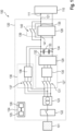
- a first example of an electrolysis system 100 comprising a multi-stage electrical power supply 120 according to an embodiment of the invention is schematically shown.
- the electrolysis system also comprises an electrolyser 110 that has an input voltage operating range, with an electrolyser input 111 connected to a power supply output 121 of the multi-stage electrical power supply 120 that is connectable through a switchgear 122 to an AC power source, in particular to a (public) AC power grid 101.
- the AC voltage received from the AC power grid 101 is supplied via the switchgear 122 in an ON state to a transformer unit 123 that converts the grid voltage to a lower voltage, e. g. below 1000 V. In the shown embodiment, it is converted to three phase-shifted AC voltage signals.
- the controller unit 124 is a programmable controller unit and comprises a processor 125 and a memory 126.
- the multi-stage electrical power supply 120 has a controller unit 124 configured to send and receive all required signals to and from the different units, elements and switches of the multi-stage electrical power supply 120 (connections not shown).
- the controller unit 124 is or comprises a programmable apparatus with at least a processor 125 and a memory 126, wherein the memory 126 comprises code portions of a computer program product, that, when executed by the processor of the programmable apparatus, enable the multi-stage electrical power supply 120 to carry out steps of an operation method as described in connection with Fig. 3 .
- the multi-stage electrical power supply 120 comprises a first power conversion unit 127 and a second power conversion unit 128 connectable to the input 111 of the electrolyser 110.
- the first power conversion unit 127 comprises a main AC-DC converter unit 129, for example using an IGBT-based rectifier, with an input connected to a high-frequency filter unit 130 with an input connected to receive the transformed low voltage AC signal from the transformer unit 123 through a circuit breaker switch 131, e. g. an air circuit breaker (ACB), for damage protection, for example, from overcurrent.
- ACB air circuit breaker
- the first power conversion unit 127 has a first output voltage operating range that comprises a first subset of the input voltage operating range of the electrolyser 110 above and equal to a threshold output voltage of the first power conversion unit 127 and the second power conversion unit 128 has a second output voltage operating range that comprises a second subset of the input voltage operating range of the electrolyser 110 below the threshold output voltage of the first power conversion unit 127.
- the first and second output voltage operating ranges only together completely comprise the input voltage operating range of the electrolyser 110.
- the first power conversion unit 127 is or comprises the main AC-DC converter unit 127 and has a first converter output 132 connected to a set of two DC-link capacitors 133, 134.
- the first power conversion unit 127 provides electrical power required by the electrolyser 110 for the first subset of the input voltage operating range via the first converter output 132 during the time when an output voltage at the first converter output 132 is above or equal to the threshold output voltage
- the second power conversion unit 128 provides electrical power required by the electrolyser 110 for the second subset of the input voltage operating range via a second converter output 135 during the time when the output voltage at the first converter output 132 is below the threshold output voltage.
- the threshold output voltage is a minimum output voltage threshold of the first power conversion unit 127.
- the controller unit 124 is configured to select the second power conversion unit 128 instead of the first power conversion unit 127 to provide electrical power to the input 111 of the electrolyser 110 when the output voltage at the first converter output 132 is below the threshold output voltage.
- the multi-stage electrical power supply 120 further comprises a switchable pre-charge circuit element 136 that is configured to pre-charge the direct current link capacitors 133, 134 when the first converter output voltage is below the threshold output voltage, in order to pre-charge the DC-link capacitors 133, 134 before they can be charged by the first power conversion unit 127.
- the shown switchable pre-charge circuit element 136 comprises pre-charge switch 137 at least for enabling and disabling the pre-charging.
- the switchable pre-charge circuit element 136 has an additional AC-DC converter unit 138 for pre-charging the DC-link capacitors 133, 134 from the AC power grid 101, if the additional AC-DC converter unit 138 is configured to work in an operating range below the output voltage threshold of the first power conversion unit 127 with the main AC-DC converter unit 129.
- the second power conversion unit 128 is or comprises a DC-DC converter unit having a second converter input 141 connected to the first converter output 132 of the first power conversion unit 127.
- the multi-stage electrical power supply 120 comprises a switchable bypass circuit 139 with a bypass switch 140, for example a contactor switch. The switchable bypass circuit is connected to bypass the second power conversion unit 128 when the bypass switch 140 is in an ON state, i.e. closed or enabled.
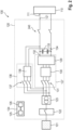
- FIG. 2 a second example of an electrolysis system 100 comprising a multi-stage electrical power supply 120 according to another embodiment of the invention is schematically shown. Elements identical or similar to the elements shown in Fig. 1 are shown with identical reference numbers. Only elements differing from Fig. 1 will be described in detail.
- the second power conversion unit is not a DC-DC converter unit.
- the additional AC-DC converter unit 138 of the switchable pre-charge circuit element 136 that is used to pre-charge the DC-link capacitors 133, 134 when the first converter output voltage is below the threshold output voltage, is considered as the second power conversion unit.
- the additional AC-DC converter unit 138 of the switchable pre-charge circuit element 136 is suitably configured to be able to ramp-up or ramp-down the electrolyser 110 during the time when the output voltage at the first power converter output is below the threshold output voltage.
- the output voltage operating range of the switchable pre-charge circuit element 136 is configured such that it comprises the second subset of the input voltage operating range of the electrolyser 110 below the minimum output voltage threshold, of the first power conversion unit 127.
- the additional AC-DC converter unit 138 may comprise, for example, a thyristor-based rectifier.
- the first converter output 132 which in this embodiment corresponds to the second converter output, is connectable to the input 111 of the electrolyser 110 via an output switch 240. This allows to connect and disconnect the power supply from the electrolyser 110.
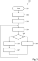
- FIG. 3 an example of a method 300 of operating a multi-stage electrical power supply for an electrolysis system according to an embodiment of the invention is schematically shown.
- start 301 of the method of operating a multi-stage electrical power supply for an electrolysis system e.g., as shown in Fig. 1 .
- an input of the multi-stage electrical power supply is connected 302 to an AC power grid
- a minimum output voltage threshold of a first power conversion unit of the multi-stage electrical power supply is determined 303 as a threshold output voltage
- an output voltage is sensed 304 at a first converter output of the first power conversion unit.
- the second power conversion unit of the multi-stage electrical power supply instead of the first power conversion unit is selected 307 to provide electrical power to the input of the electrolyser when, i.e. during the time when, the output voltage at the first converter output is below the threshold output voltage.
- the method then continues with the step of sensing 304 an output voltage at a first converter output of the first power conversion unit.
- the method ends, for example, when the multi-stage power supply is deactivated.
- the step of determining 305 if the output voltage at the first converter output is below the threshold output voltage comprises determining that the second power conversion unit is a DC-DC converter unit having a second converter input connected to the first converter output of the first power conversion unit and that the multi-stage electrical power supply further comprises a switchable bypass circuit with a bypass switch, connected to bypass the second power conversion unit when the bypass switch is in an ON state, the step of selecting 306 the first power conversion unit to provide electrical power to an input of an electrolyser when the output voltage at the first converter output is not below the threshold output voltage comprises switching the bypass switch to the ON state, and the step of selecting 307 a second power conversion unit of the multi-stage electrical power supply instead of the first power conversion unit to provide electrical power to the input of the electrolyser when the output voltage at the first converter output is below the threshold output voltage comprises switching the bypass switch to an OFF state.
- a graph of an example of an input voltage V over an input current I at an electrolyser input connected to a multi-stage electrical power supply is schematically illustrated for an electrolysis system with a multi-stage power supply as shown in Fig. 1 .
- Curves are shown for electrolyser loading 401, electrolyser de-loading 402, electrolyser BOL (begin of lifetime) 403, and electrolyser EOL (end of lifetime) 404.
- the bypass switch is switched to ON state 405
- the DC-DC converter unit and the AC-DC converter unit are enabled (second subset of input voltage range 406).
- a minimum continuous operation limit 408 may be defined to distinguish power provision during a ramping mode 409 and power provision during a continuous operation mode 410. Further, the polarization voltage limit 411 is indicated.
- the terms “input” and “output” refer to input and output interfaces, pins or any other input and output connection lines.
- the terms “input” and “output” address the complete input or output interface, i.e., both connection lines in a DC circuit and lines for all three shown phases of an AC connection with three phases.
- connection lines in the figures usually only one of these set of connection lines is numbered by a reference numeral although it identifies the set of connection lines.
- second converter output merely addresses an output of the second converter and does, e. g., not imply that the second converter also has a first output.
- the invention relates to a multi-stage electrical power supply 120 for an electrolysis system 100, wherein an electrolyser 110 has an input voltage operating range, and the multi-stage electrical power supply 120 comprises a controller unit 124, at least a first and a second power conversion unit 127,128 connectable to an input 111 of the electrolyser 110, and DC-link capacitors 133, 134, wherein the first power conversion unit 127 has a first output voltage operating range that comprises a first subset of the input voltage operating range of the electrolyser 110 above and equal to a threshold output voltage of the first power conversion unit 127, the second power conversion unit 128 has a second output voltage operating range that comprises a second subset of said input voltage operating range below said threshold output voltage, the first and second output voltage operating ranges only together completely comprise the input voltage operating range of the electrolyser 110, the first power conversion unit 127 comprises a main AC-DC converter unit having a first converter output 132 connected to the DC-link capacitors 133, 134, and being
- an electrolysis system 100 a method 300 of operating a multi-stage electrical power supply for an electrolysis system, a computer program product, and a computer readable storage medium are provided.
Landscapes
- Engineering & Computer Science (AREA)
- Power Engineering (AREA)
- Direct Current Feeding And Distribution (AREA)
- Electrolytic Production Of Non-Metals, Compounds, Apparatuses Therefor (AREA)
Priority Applications (4)
| Application Number | Priority Date | Filing Date | Title |
|---|---|---|---|
| EP23197751.3A EP4525283A1 (fr) | 2023-09-15 | 2023-09-15 | Alimentation électrique multi-étagée pour un système d'électrolyse |
| PCT/EP2024/074564 WO2025056366A1 (fr) | 2023-09-15 | 2024-09-03 | Alimentation électrique à étages multiples pour système d'électrolyse |
| CN202480058018.9A CN121844477A (zh) | 2023-09-15 | 2024-09-03 | 电解系统的多级电源 |
| AU2024340286A AU2024340286A1 (en) | 2023-09-15 | 2024-09-03 | Multi-stage electrical power supply for an electrolysis system |
Applications Claiming Priority (1)
| Application Number | Priority Date | Filing Date | Title |
|---|---|---|---|
| EP23197751.3A EP4525283A1 (fr) | 2023-09-15 | 2023-09-15 | Alimentation électrique multi-étagée pour un système d'électrolyse |
Publications (1)
| Publication Number | Publication Date |
|---|---|
| EP4525283A1 true EP4525283A1 (fr) | 2025-03-19 |
Family
ID=88093177
Family Applications (1)
| Application Number | Title | Priority Date | Filing Date |
|---|---|---|---|
| EP23197751.3A Withdrawn EP4525283A1 (fr) | 2023-09-15 | 2023-09-15 | Alimentation électrique multi-étagée pour un système d'électrolyse |
Country Status (4)
| Country | Link |
|---|---|
| EP (1) | EP4525283A1 (fr) |
| CN (1) | CN121844477A (fr) |
| AU (1) | AU2024340286A1 (fr) |
| WO (1) | WO2025056366A1 (fr) |
Citations (2)
| Publication number | Priority date | Publication date | Assignee | Title |
|---|---|---|---|---|
| US10439495B2 (en) * | 2015-02-03 | 2019-10-08 | Siemens Aktiengesellschaft | Regulating voltage supplied to a load using switching units |
| CN110971116A (zh) * | 2019-12-24 | 2020-04-07 | 湖南时铭电气有限公司 | 一种电压源型逆变器的软启动电路及软启动方法 |
Family Cites Families (2)
| Publication number | Priority date | Publication date | Assignee | Title |
|---|---|---|---|---|
| US9893628B2 (en) * | 2015-10-30 | 2018-02-13 | Apple Inc. | AC-DC power converters with improved voltage output level transitions |
| EP3556905A1 (fr) * | 2018-04-19 | 2019-10-23 | Siemens Aktiengesellschaft | Ensemble circuit, procédé de fonctionnement d'un ensemble circuit et dispositif d'électrolyse |
-
2023
- 2023-09-15 EP EP23197751.3A patent/EP4525283A1/fr not_active Withdrawn
-
2024
- 2024-09-03 AU AU2024340286A patent/AU2024340286A1/en active Pending
- 2024-09-03 WO PCT/EP2024/074564 patent/WO2025056366A1/fr active Pending
- 2024-09-03 CN CN202480058018.9A patent/CN121844477A/zh active Pending
Patent Citations (2)
| Publication number | Priority date | Publication date | Assignee | Title |
|---|---|---|---|---|
| US10439495B2 (en) * | 2015-02-03 | 2019-10-08 | Siemens Aktiengesellschaft | Regulating voltage supplied to a load using switching units |
| CN110971116A (zh) * | 2019-12-24 | 2020-04-07 | 湖南时铭电气有限公司 | 一种电压源型逆变器的软启动电路及软启动方法 |
Also Published As
| Publication number | Publication date |
|---|---|
| WO2025056366A1 (fr) | 2025-03-20 |
| CN121844477A (zh) | 2026-04-10 |
| AU2024340286A1 (en) | 2026-03-05 |
Similar Documents
| Publication | Publication Date | Title |
|---|---|---|
| US11299051B2 (en) | Electric charging system and method | |
| EP2467928B1 (fr) | Alimentation électrique triphasée secourue à grande puissance | |
| JP6227041B2 (ja) | マルチレベルインバータ | |
| CN104106194B (zh) | 电力变换装置 | |
| US10784713B2 (en) | Uninterruptible power supply device | |
| US20130208521A1 (en) | Hybrid hvdc converter | |
| JP2009033840A (ja) | 給電システムおよび給電システムの制御方法 | |
| CN108702101B (zh) | 电力变换装置及其运转方法 | |
| US12046782B2 (en) | Fuel cell power system | |
| US20200136423A1 (en) | Control of dc voltage distribution system | |
| JP2017135889A (ja) | 電力変換装置、及び電力変換システム | |
| US10886744B2 (en) | Power conversion system, power supply system and power conversion device | |
| JP2017184607A (ja) | 配電システム及び電力合成回路 | |
| EP4525283A1 (fr) | Alimentation électrique multi-étagée pour un système d'électrolyse | |
| EP4012869A1 (fr) | Dispositif de conversion de puissance | |
| JP2016220431A (ja) | 電力変換装置 | |
| US12614919B2 (en) | Uninterruptible power supply apparatus | |
| US20240405597A1 (en) | Uninterruptible Power Supply, Control Method And Power Supply System | |
| KR102330697B1 (ko) | 계통 연계형 에너지 저장 시스템 | |
| JP4147350B2 (ja) | 無停電電源装置 | |
| CN121693836A (zh) | 用于电金属加热炉系统的变流器系统 | |
| CN119010613A (zh) | 用于给用电器、尤其是电解装置供给直流电压的设备 | |
| CN116154837A (zh) | 逆变器及其控制方法、以及供电系统 | |
| CN119174079A (zh) | 电力供给系统 |
Legal Events
| Date | Code | Title | Description |
|---|---|---|---|
| PUAI | Public reference made under article 153(3) epc to a published international application that has entered the european phase |
Free format text: ORIGINAL CODE: 0009012 |
|
| STAA | Information on the status of an ep patent application or granted ep patent |
Free format text: STATUS: THE APPLICATION HAS BEEN PUBLISHED |
|
| AK | Designated contracting states |
Kind code of ref document: A1 Designated state(s): AL AT BE BG CH CY CZ DE DK EE ES FI FR GB GR HR HU IE IS IT LI LT LU LV MC ME MK MT NL NO PL PT RO RS SE SI SK SM TR |
|
| STAA | Information on the status of an ep patent application or granted ep patent |
Free format text: STATUS: THE APPLICATION IS DEEMED TO BE WITHDRAWN |
|
| 18D | Application deemed to be withdrawn |
Effective date: 20250920 |