EP4525480A1 - Lentille acoustique et système de haut-parleur - Google Patents
Lentille acoustique et système de haut-parleur Download PDFInfo
- Publication number
- EP4525480A1 EP4525480A1 EP23803531.5A EP23803531A EP4525480A1 EP 4525480 A1 EP4525480 A1 EP 4525480A1 EP 23803531 A EP23803531 A EP 23803531A EP 4525480 A1 EP4525480 A1 EP 4525480A1
- Authority
- EP
- European Patent Office
- Prior art keywords
- partition plates
- sound waves
- acoustic lens
- loudspeaker
- directivity
- Prior art date
- Legal status (The legal status is an assumption and is not a legal conclusion. Google has not performed a legal analysis and makes no representation as to the accuracy of the status listed.)
- Pending
Links
Images


Classifications
-
- H—ELECTRICITY
- H04—ELECTRIC COMMUNICATION TECHNIQUE
- H04R—LOUDSPEAKERS, MICROPHONES, GRAMOPHONE PICK-UPS OR LIKE ACOUSTIC ELECTROMECHANICAL TRANSDUCERS; ELECTRIC HEARING AIDS; PUBLIC ADDRESS SYSTEMS
- H04R1/00—Details of transducers, loudspeakers or microphones
- H04R1/20—Arrangements for obtaining desired frequency or directional characteristics
- H04R1/32—Arrangements for obtaining desired frequency or directional characteristics for obtaining desired directional characteristic only
- H04R1/34—Arrangements for obtaining desired frequency or directional characteristics for obtaining desired directional characteristic only by using a single transducer with sound reflecting, diffracting, directing or guiding means
- H04R1/345—Arrangements for obtaining desired frequency or directional characteristics for obtaining desired directional characteristic only by using a single transducer with sound reflecting, diffracting, directing or guiding means for loudspeakers
-
- G—PHYSICS
- G10—MUSICAL INSTRUMENTS; ACOUSTICS
- G10K—SOUND-PRODUCING DEVICES; METHODS OR DEVICES FOR PROTECTING AGAINST, OR FOR DAMPING, NOISE OR OTHER ACOUSTIC WAVES IN GENERAL; ACOUSTICS NOT OTHERWISE PROVIDED FOR
- G10K11/00—Methods or devices for transmitting, conducting or directing sound in general; Methods or devices for protecting against, or for damping, noise or other acoustic waves in general
- G10K11/18—Methods or devices for transmitting, conducting or directing sound
- G10K11/26—Sound-focusing or directing, e.g. scanning
- G10K11/30—Sound-focusing or directing, e.g. scanning using refraction, e.g. acoustic lenses
-
- H—ELECTRICITY
- H04—ELECTRIC COMMUNICATION TECHNIQUE
- H04R—LOUDSPEAKERS, MICROPHONES, GRAMOPHONE PICK-UPS OR LIKE ACOUSTIC ELECTROMECHANICAL TRANSDUCERS; ELECTRIC HEARING AIDS; PUBLIC ADDRESS SYSTEMS
- H04R1/00—Details of transducers, loudspeakers or microphones
- H04R1/20—Arrangements for obtaining desired frequency or directional characteristics
- H04R1/32—Arrangements for obtaining desired frequency or directional characteristics for obtaining desired directional characteristic only
- H04R1/34—Arrangements for obtaining desired frequency or directional characteristics for obtaining desired directional characteristic only by using a single transducer with sound reflecting, diffracting, directing or guiding means
-
- H—ELECTRICITY
- H04—ELECTRIC COMMUNICATION TECHNIQUE
- H04R—LOUDSPEAKERS, MICROPHONES, GRAMOPHONE PICK-UPS OR LIKE ACOUSTIC ELECTROMECHANICAL TRANSDUCERS; ELECTRIC HEARING AIDS; PUBLIC ADDRESS SYSTEMS
- H04R2499/00—Aspects covered by H04R or H04S not otherwise provided for in their subgroups
- H04R2499/10—General applications
- H04R2499/13—Acoustic transducers and sound field adaptation in vehicles
Definitions
- the present invention relates to an acoustic lens that controls sound directivity, and a loudspeaker system.
- the plurality of second partition plates are disposed such that the total number of the plurality of second partition plates that overlap monotonically decreases in the traveling direction of the sound wave with increasing distance from the center of the plurality of second partition plates along the second direction.
- This provides an advantage that it is easy to set the directivity of sound waves closer to the center of the plurality of second partition plates along the second direction.
- FIG. 2 is an overview diagram illustrating a usage example of loudspeaker system 100 including acoustic lens 1 according to the embodiment.
- the indication of loudspeaker 2 is omitted.
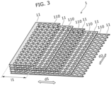
- FIG. 3 is an overview diagram illustrating the configuration of acoustic lens 1 according to the embodiment.
- FIG. 3 is an overview diagram illustrating the configuration of acoustic lens 1 according to the embodiment.
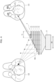
- FIG. 4 is an illustration of directivity of acoustic lens 1 according to the embodiment.
- loudspeaker system 100 includes acoustic lens 1 and loudspeaker 2 (see FIG. 4 ).
- Loudspeaker system 100 is a system for allowing target user U1 to hear the sounds of sound waves W1 (see FIG. 4 ) emitted from loudspeaker 2 via acoustic lens 1.
- loudspeaker systems 100 are provided in each of seats 3 and 3A in a moving body such as a vehicle.
- seat 3 is a driver's seat in a vehicle and seat 3A is a passenger's seat in the vehicle.
- Seats 3 and 3A are aligned in the right-left direction (horizontal direction) of the vehicle on the front side of the vehicle.
- the following describes assuming that the right-left direction (horizontal direction) of the vehicle is "first direction d1" and the height direction (vertical direction) of the vehicle is "second direction d2", unless otherwise specified.
- Loudspeaker 2 is a device that outputs sound waves W1 by converting the electric signals of, for instance, sound signals into vibrations of a vibration board.
- the size, shape, and structure of the vibration board, a magnetic circuit, a frame, or the like included in loudspeaker 2 are not specifically limited.
- loudspeaker 2 is an electrodynamic loudspeaker including a cone diaphragm. Loudspeaker 2 emits sound waves W1 to acoustic lens 1. With this, sound waves W1 emitted from loudspeaker 2 pass through acoustic lens 1 and are emitted to outside (to the air).
- the plurality of first partition plates 11 are disposed aligned apart from each other in the traveling direction of sound waves W1 emitted from loudspeaker 2, as illustrated in FIG. 3 and FIG. 4 .
- Each first partition plate 11 may be supported by, for example, a frame-like member provided at the outer edge of first partition plate 11 or supported by a spacer provided between neighboring first partition plates 11, although not shown in the figures.
- first direction d1 is the horizontal direction and second direction d2 is the vertical direction. Accordingly, in the embodiment, first direction d1 and second direction d2 are orthogonal to each other. Note that first direction d1 and second direction d2 need to intersect each other and need not be orthogonal to each other.
- first direction d1 is a direction in which the directivity of sound waves W1 is controlled.
- the plurality of first partition plates 11 are disposed such that the number of the plurality of first partition plates 11 that overlap in the traveling direction of sound waves W1 monotonically decreases from one end of the plurality of first partition plates 11 (the left side in FIG. 3 ) to the other end (the right side in FIG. 3 ) in first direction d1.
- the plurality of first partition plates 11 are disposed such that the number of the plurality of first partition plates 11 that overlap in the traveling direction of sound waves W1 monotonically decreases toward one end of the plurality of first partition plates 11 in first direction d1 closer to the directivity of sound waves W1 that is desired to be set.
- the plurality of first partition plates 11 are disposed so that lengths l1 of the plurality of first partition plates 11 increase toward loudspeaker 2 in the traveling direction of sound waves W1.
- length l1 of first partition plate 11 in first direction d1 located farthest from loudspeaker 2 is the shortest and length l1 of first partition plate 11 in first direction d1 located closest to loudspeaker 2 is the longest.
- the directivity of sound waves W1 in first direction d1 is controlled by changing the lengths of paths through which sound waves W1 pass.
- the directivity of sound waves W1 is directed toward one side of first direction d1.
- acoustic lens 1 and loudspeaker system 100 will be described.
- the lengths, in first direction d1, of the plurality of first partition plates 11 aligned apart from each other in the traveling direction are mutually different. Accordingly, with acoustic lens 1 according to the embodiment, since the lengths of paths through which sound waves 1 pass can be adjusted according to the number of holes 110 through which sound waves W1 pass, it is easy to control the directivity of sound waves W1 (directivity of sound waves W1 in first direction d1 in this case).
- acoustic lens 1 is capable of controlling the directivity of sound waves W1 in the horizontal direction.
- Acoustic lens 1 and loudspeaker system 100 that uses acoustic lens 1 may overcome the problems loudspeaker system 200 according to the comparative example has.
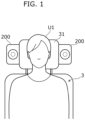
- loudspeaker system 100 is provided in the vicinity of the left ear and in the vicinity of the right ear of user U1 seated on seat 3, and acoustic lens 1 is placed so that the directivity of sound waves W1 is directed toward user U1 in the horizontal direction (first direction d1), as illustrated in FIG. 2 .
- sound waves W1 emitted from loudspeaker 2 are emitted via acoustic lens 1 so that the directivity of sound waves W1 is directed toward user U1 in the horizontal direction, sounds are unlikely to leak to user U2 seated on seat 3A next to seat 3.
- loudspeaker system 100 is provided in the vicinity of the left ear and in the vicinity of the right ear of user U2 seated on seat 3A next to seat 3, and acoustic lens 1 is placed so that the directivity of sound waves W1 is directed toward user U2 in the horizontal direction (first direction d1).
- first direction d1 since sound waves W1 emitted from loudspeaker 2 are emitted via acoustic lens 1 so that the directivity of sound waves W1 is directed toward user U2 in the horizontal direction, sounds are unlikely to leak to user U1 seated on seat 3.
- acoustic lens 1 according to the embodiment and loudspeaker system 100 that uses acoustic lens 1 provides an advantage that sounds that leak to a person other than target user U1 (or user U2) is easily suppressed.
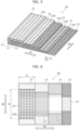
- FIG. 5 is an overview diagram illustrating the configuration of acoustic lens 1A according to Variation 1 of the embodiment.
- Acoustic lens 1A according to Variation 1 is different from acoustic lens 1 according to the embodiment in that diameters R1 of holes 110 decrease with increasing distance from loudspeaker 2 in the traveling direction of sound waves W1 (stated differently, the thickness direction of first partition plates 11).
- diameter R1 of each hole 110 in first partition plate 11 located closest to loudspeaker 2 in the traveling direction of sound waves W1 is the largest and diameter R1 of each hole 110 in first partition plate 11 located farthest from loudspeaker 2 in the traveling direction of sound waves W1 is the smallest.
- a ratio of the total area of holes 110 to the area of first partition plate 11 in any first partition plate 11 is defined as an opening ratio. It therefore can be said that in acoustic lens 1A according to Variation 1, the opening ratios of the plurality of first partition plates 11 decrease with increasing distance from loudspeaker 2.
- acoustic lens 1A according to Variation 1 As described above, in acoustic lens 1A according to Variation 1, the opening ratios of the plurality of first partition plates 11 decrease with increasing distance from loudspeaker 2 in the traveling direction of sound waves W1. Therefore, the lengths of paths through which sound waves W1 pass increase as the number of holes through which sound waves W1 pass increases. Accordingly, acoustic lens 1A according to Variation 1, as compared with acoustic lens 1 according to the embodiment, provides an advantage that the directivity of sound waves W1 is controlled to be directed toward one side of first direction d1 (the left side in FIG. 5 ) and the directivity of sound waves W1 is likely to be sharp.
- acoustic lens 1B according to Variation 2 has an advantage that the directivity of sound waves W1 (the directivity of sound waves W1 in second direction d2 in this case) is easily controlled by making the lengths of the plurality of second partition plates 12 aligned apart from each other in the traveling direction of sound waves W1 mutually different.
- acoustic lens 1B according to Variation 2, as is the case of Variation 1, the opening ratios of first partition plates 11 may decrease with increasing distance from loudspeaker 2 in the traveling direction of sound waves W1.
- the opening ratios of second partition plates 12 may decrease with increasing distance from loudspeaker 2 in the traveling direction of sound waves W1.
- the opening ratio of second partition plate 12 is defined by the ratio of the total area of holes 120 to the area of second partition plate 12 in any second partition plate 12.
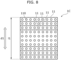
- FIG. 8 is an overview diagram illustrating the configuration of acoustic lens 1C according to Variation 3 of the embodiment.
- Acoustic lens 1C according to Variation 3 differs from acoustic lens 1 according to the embodiment in that first direction d1 is defined as a vertical direction and a plurality of first partition plates 11 are disposed such that the number of the plurality of first partition plates 11 that overlap in the traveling direction of sound waves W1 decreases with increasing distance from the center of the plurality of first partition plates 11 along first direction d1.
- acoustic lens 1C according to Variation 3 is configured to mainly control the directivity of sound waves W1 in the vertical direction of sound waves W1, which is different from acoustic lens 1 according to the embodiment that is configured to mainly control the directivity of sound waves W1 in the horizontal direction of sound waves W1.
- lengths l1 of the plurality of first partition plates 11 in first direction d1 are mutually different, as illustrated in FIG. 8 .
- the plurality of first partition plates 11 are disposed such that the number of the plurality of first partition plates 11 that overlap in the traveling direction of sound waves W1 decreases with increasing distance from the center of the plurality of first partition plates 11 along first direction d1.
- the plurality of first partition plates 11 are disposed such that the number of the plurality of first partition plates 11 that overlap in the traveling direction of sound waves W1 monotonically increases toward one end of the plurality of first partition plates 11 along first direction d1 closer to the directivity of sound waves W1 that is desired to be set.
- acoustic lens 1C is capable of controlling the directivity of sound waves W1 in the vertical direction.
- holes 110 and 120 that are adjacent to each other in the traveling direction of sound waves W1 may be disposed not to overlap each other when viewed along the traveling direction of sound waves W1. Stated differently, at least one or more holes 110 and one or more holes 120 need not overlap each other when viewed along the traveling direction of sound waves W1.
- This configuration provides an advantage that the directivity of sound waves W1 is likely to be sharp since the lengths of paths through which sound waves W1 pass can be increased.
- the present disclosure is useful as a member that controls the directivity of sound waves emitted from a loudspeaker.
Landscapes
- Health & Medical Sciences (AREA)
- Otolaryngology (AREA)
- Physics & Mathematics (AREA)
- Engineering & Computer Science (AREA)
- Acoustics & Sound (AREA)
- Signal Processing (AREA)
- Multimedia (AREA)
- Obtaining Desirable Characteristics In Audible-Bandwidth Transducers (AREA)
Applications Claiming Priority (3)
| Application Number | Priority Date | Filing Date | Title |
|---|---|---|---|
| US202263340653P | 2022-05-11 | 2022-05-11 | |
| JP2023073692 | 2023-04-27 | ||
| PCT/JP2023/017255 WO2023219054A1 (fr) | 2022-05-11 | 2023-05-08 | Lentille acoustique et système de haut-parleur |
Publications (2)
| Publication Number | Publication Date |
|---|---|
| EP4525480A1 true EP4525480A1 (fr) | 2025-03-19 |
| EP4525480A4 EP4525480A4 (fr) | 2025-08-06 |
Family
ID=88730477
Family Applications (1)
| Application Number | Title | Priority Date | Filing Date |
|---|---|---|---|
| EP23803531.5A Pending EP4525480A4 (fr) | 2022-05-11 | 2023-05-08 | Lentille acoustique et système de haut-parleur |
Country Status (5)
| Country | Link |
|---|---|
| US (1) | US20250056155A1 (fr) |
| EP (1) | EP4525480A4 (fr) |
| JP (1) | JPWO2023219054A1 (fr) |
| CN (1) | CN119174194A (fr) |
| WO (1) | WO2023219054A1 (fr) |
Family Cites Families (6)
| Publication number | Priority date | Publication date | Assignee | Title |
|---|---|---|---|---|
| US2580439A (en) * | 1949-09-07 | 1952-01-01 | Bell Telephone Labor Inc | Directional acoustic system |
| US2805728A (en) * | 1953-08-27 | 1957-09-10 | Gen Dynamics Corp | Sound dispersion device with internal divergent acoustical lens |
| JPS541231Y2 (fr) * | 1972-11-07 | 1979-01-20 | ||
| JPS5632838B2 (fr) * | 1973-03-06 | 1981-07-30 | ||
| JPS51103930U (fr) * | 1975-02-18 | 1976-08-20 | ||
| JPS55155179U (fr) | 1979-04-24 | 1980-11-08 |
-
2023
- 2023-05-08 EP EP23803531.5A patent/EP4525480A4/fr active Pending
- 2023-05-08 JP JP2024520440A patent/JPWO2023219054A1/ja active Pending
- 2023-05-08 CN CN202380036858.0A patent/CN119174194A/zh active Pending
- 2023-05-08 WO PCT/JP2023/017255 patent/WO2023219054A1/fr not_active Ceased
-
2024
- 2024-10-29 US US18/930,071 patent/US20250056155A1/en active Pending
Also Published As
| Publication number | Publication date |
|---|---|
| WO2023219054A1 (fr) | 2023-11-16 |
| EP4525480A4 (fr) | 2025-08-06 |
| CN119174194A (zh) | 2024-12-20 |
| US20250056155A1 (en) | 2025-02-13 |
| JPWO2023219054A1 (fr) | 2023-11-16 |
Similar Documents
| Publication | Publication Date | Title |
|---|---|---|
| EP2471276B1 (fr) | Haut-parleur omnidirectionnel | |
| AU2012272519B2 (en) | Acoustic horn arrangement | |
| EP3734991B1 (fr) | Haut-parleur, système de haut-parleur, système de haut-parleur stéréo et système de haut-parleur stéréo embarqué | |
| EP2894873B1 (fr) | Ouverture allongée et cannelée pour transducteur acoustique | |
| EP2701401A2 (fr) | Moteur de haut-parleur avec deux ensembles d'électro-aimants | |
| US7965847B2 (en) | Speaker system | |
| EP3420738B1 (fr) | Collecteur plan pour haut-parleur permettant une meilleure dispersion sonore | |
| EP4525480A1 (fr) | Lentille acoustique et système de haut-parleur | |
| JP7310970B2 (ja) | スピーカ | |
| KR102097891B1 (ko) | 스피커용 입체 음향 가이드 및 이를 구비한 스피커 | |
| EP4525479A1 (fr) | Lentille acoustique et système de haut-parleur | |
| KR101634279B1 (ko) | 스피커용 입체 음향 가이드, 및 이를 구비한 스피커 | |
| US20190306616A1 (en) | Loudspeaker, acoustic waveguide, and method | |
| US10136224B2 (en) | Electrodynamic sound transducer | |
| JP2018201175A (ja) | スピーカー | |
| HK1171892A (zh) | 全向扬声器 |
Legal Events
| Date | Code | Title | Description |
|---|---|---|---|
| STAA | Information on the status of an ep patent application or granted ep patent |
Free format text: STATUS: THE INTERNATIONAL PUBLICATION HAS BEEN MADE |
|
| PUAI | Public reference made under article 153(3) epc to a published international application that has entered the european phase |
Free format text: ORIGINAL CODE: 0009012 |
|
| STAA | Information on the status of an ep patent application or granted ep patent |
Free format text: STATUS: REQUEST FOR EXAMINATION WAS MADE |
|
| 17P | Request for examination filed |
Effective date: 20241031 |
|
| AK | Designated contracting states |
Kind code of ref document: A1 Designated state(s): AL AT BE BG CH CY CZ DE DK EE ES FI FR GB GR HR HU IE IS IT LI LT LU LV MC ME MK MT NL NO PL PT RO RS SE SI SK SM TR |
|
| A4 | Supplementary search report drawn up and despatched |
Effective date: 20250703 |
|
| RIC1 | Information provided on ipc code assigned before grant |
Ipc: H04R 1/34 20060101AFI20250627BHEP Ipc: G10K 11/30 20060101ALI20250627BHEP |
|
| DAV | Request for validation of the european patent (deleted) | ||
| DAX | Request for extension of the european patent (deleted) |