EP4525552A1 - Noeud de réseau et procédé de communication - Google Patents
Noeud de réseau et procédé de communication Download PDFInfo
- Publication number
- EP4525552A1 EP4525552A1 EP22941747.2A EP22941747A EP4525552A1 EP 4525552 A1 EP4525552 A1 EP 4525552A1 EP 22941747 A EP22941747 A EP 22941747A EP 4525552 A1 EP4525552 A1 EP 4525552A1
- Authority
- EP
- European Patent Office
- Prior art keywords
- network node
- pdu session
- terminal
- session
- information
- Prior art date
- Legal status (The legal status is an assumption and is not a legal conclusion. Google has not performed a legal analysis and makes no representation as to the accuracy of the status listed.)
- Pending
Links
Images


Classifications
-
- H—ELECTRICITY
- H04—ELECTRIC COMMUNICATION TECHNIQUE
- H04W—WIRELESS COMMUNICATION NETWORKS
- H04W8/00—Network data management
- H04W8/02—Processing of mobility data, e.g. registration information at HLR [Home Location Register] or VLR [Visitor Location Register]; Transfer of mobility data, e.g. between HLR, VLR or external networks
-
- H—ELECTRICITY
- H04—ELECTRIC COMMUNICATION TECHNIQUE
- H04W—WIRELESS COMMUNICATION NETWORKS
- H04W12/00—Security arrangements; Authentication; Protecting privacy or anonymity
- H04W12/08—Access security
-
- H—ELECTRICITY
- H04—ELECTRIC COMMUNICATION TECHNIQUE
- H04W—WIRELESS COMMUNICATION NETWORKS
- H04W12/00—Security arrangements; Authentication; Protecting privacy or anonymity
- H04W12/06—Authentication
-
- H—ELECTRICITY
- H04—ELECTRIC COMMUNICATION TECHNIQUE
- H04W—WIRELESS COMMUNICATION NETWORKS
- H04W76/00—Connection management
- H04W76/10—Connection setup
-
- H—ELECTRICITY
- H04—ELECTRIC COMMUNICATION TECHNIQUE
- H04W—WIRELESS COMMUNICATION NETWORKS
- H04W76/00—Connection management
- H04W76/10—Connection setup
- H04W76/12—Setup of transport tunnels
-
- H—ELECTRICITY
- H04—ELECTRIC COMMUNICATION TECHNIQUE
- H04W—WIRELESS COMMUNICATION NETWORKS
- H04W76/00—Connection management
- H04W76/20—Manipulation of established connections
- H04W76/22—Manipulation of transport tunnels
Definitions
- the present invention relates to a network node and a communication method in a radio communication system.
- New Radio (also referred to as "5G"), which is a successor system of long term evolution (LTE), a network architecture including 5GC (5G Core Network) corresponding to EPC (Evolved Packet Core), which is a core network in LTE (Long Term Evolution), and NG-RAN (Next Generation-Radio Access Network) corresponding to E-UTRAN (Evolved Universal Terrestrial Radio Access Network), which is RAN (Radio Access Network) in the LTE network architecture, is under study (for example, Non-Patent Document 1 and Non-Patent Document 2).
- 5GC 5G Core Network
- EPC Evolved Packet Core
- NG-RAN Next Generation-Radio Access Network
- E-UTRAN Evolved Universal Terrestrial Radio Access Network
- an authentication device or the like detects that a person approaches a shared terminal, and notifies an AF (for example, an application server) of the approach.
- the AF transmits data of the AF to the shared terminal.
- a mechanism for charging according to the amount of use data of the AF has been studied.
- exclusive control by identified users cannot be performed, and for example, another application server of another person can simultaneously transmit other application data to the terminal.
- the present invention has been made in view of the above, and it is an object of the present invention to realize appropriate exclusive control in a terminal shared by a plurality of users in a radio communication system.
- a network node including:
- technology is provided that enables appropriate exclusive control to be realized in a terminal shared by a plurality of users in a radio communication system.
- existing technology may be used as appropriate.
- the existing technology is, for example, existing NR or LTE, but is not limited to existing NR or LTE.
- LTE Long Term Evolution
- the term "LTE" used in the present specification has a broad meaning including LTE-Advanced and schemes (example: NR) subsequent to LTE-Advanced unless otherwise specified.
- a synchronization signal (SS), a primary SS (PSS), a secondary SS (SSS), a physical broadcast channel (PBCH), a physical random access channel (PRACH), a physical downlink control channel (PDCCH), a physical downlink shared channel (PDSCH), a physical uplink control channel (PUCCH), and a physical uplink shared channel (PUSCH) used in the existing LTE are used.
- SS synchronization signal
- PSS primary SS
- SSS secondary SS
- PBCH physical random access channel
- PDCCH physical downlink control channel
- PDSCH physical downlink shared channel
- PUCCH physical uplink control channel
- PUSCH physical uplink shared channel
- PUSCH physical uplink shared channel
- the duplex scheme may be a time division duplex (TDD) scheme, a frequency division duplex (FDD) scheme, or another scheme (for example, flexible duplex).
- TDD time division duplex
- FDD frequency division duplex
- flexible duplex another scheme
- a radio parameter or the like being "configured” may mean that a predetermined value is preconfigured or that a radio parameter notified from a base station or a terminal is configured.
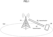
- FIG. 1 is a diagram for explaining a radio communication system according to an embodiment of the present invention.
- the radio communication system according to the embodiment of the present invention includes a base station 10 and a terminal 20.
- a base station 10 and one terminal 20 are illustrated in FIG. 1 , this is merely an example, and a plurality of base stations 10 and a plurality of terminals 20 may be provided.
- the base station 10 is a communication apparatus that provides one or more cells and performs radio communication with the terminal 20.
- the physical resource of the radio signal is defined in a time domain and a frequency domain, and the time domain is defined by the number of orthogonal frequency division multiplexing (OFDM) symbols.
- the frequency domain may be defined by the number of subcarriers or the number of resource blocks.
- a transmission time interval (TTI) in the time domain may be a slot, or a TTI may be a subframe.
- the base station 10 transmits a synchronization signal and system information to the terminal 20.
- the synchronization signal is, for example, NR-PSS and NR-SSS.
- the system information is transmitted by, for example, NR-PBCH and is also referred to as broadcast information.
- the synchronization signal and the system information may be referred to as SSB (SS/PBCH block).
- the base station 10 transmits a control signal or data to the terminal 20 in downlink (DL), and receives a control signal or data from the terminal 20 in uplink (UL).
- Both the base station 10 and the terminal 20 can transmit and receive signals by performing beamforming.
- both the base station 10 and the terminal 20 can apply communication by multiple input multiple output (MIMO) in DL or UL.
- MIMO multiple input multiple output
- Both the base station 10 and the terminal 20 may perform communication via a secondary cell (SCell) and a primary cell (PCell) by carrier aggregation (CA). Furthermore, the terminal 20 may perform communication via a primary cell of the base station 10 and a primary secondary cell group cell (PSCell:Primary SCG Cell) of another base station 10 by dual connectivity (DC).
- SCell secondary cell
- PCell primary cell
- DC dual connectivity
- the terminal 20 is a communication apparatus having a radio communication function, such as a smartphone, a mobile phone, a tablet, a wearable terminal, and a machine-to-machine (M2M) communication module. As illustrated in FIG. 1 , the terminal 20 receives a control signal or data from the base station 10 in DL and transmits a control signal or data to the base station 10 in UL, thereby using various communication services provided by the radio communication system. The terminal 20 receives various reference signals transmitted from the base station 10 and measures the channel quality based on the reception result of the reference signal.
- the terminal 20 may be referred to as UE, and the base station 10 may be referred to as gNB.
- FIG. 2 is a diagram showing an example of a configuration of a radio communication system according to an embodiment of the present invention.
- the radio communication system includes a RAN 10, the terminal 20, a core network 30, and a data network (DN) 40.
- DN data network
- the core network 30 is a network including switches, a subscriber information management apparatus, and the like.
- the core network 30 includes a network node that realizes a U-Plane function and a network node group that realizes a C-Plane function group.
- the U-Plane function is a function of executing a transmission and reception process of user data.
- the network node that realizes the U-Plane function is, for example, a user plane function (UPF) 380.
- the UPF 380 is a network node having functions such as a protocol data unit (PDU) session point for interconnection with the DN 40 to the outside, packet routing and forwarding, and quality of service (QoS) handling of the user plane.
- PDU protocol data unit
- QoS quality of service
- the UPF 380 controls data transmission and reception between the DN 40 and the terminal 20.
- the UPF 380 and the DN 40 may be composed of one or more network slices.
- the C-Plane function group is a function group that executes a series of control processes for establishing communication and the like.
- the network node group that realizes the C-Plane function group includes, for example, an access and mobility management function (AMF) 310, a unified data management (UDM) 320, a network exposure function (NEF) 330, a network repository function (NRF) 340, an authentication server function (AUSF) 350, a policy control function (PCF) 360, a session management function (SMF) 370, and an application function (AF) 390.
- AMF access and mobility management function
- UDM unified data management
- NEF network exposure function
- NRF network repository function
- AUSF authentication server function
- PCF policy control function
- SMF session management function
- AF application function
- the AMF 310 is a network node having functions such as termination of a RAN interface, termination of a non-access stratum (NAS), registration management, connection management, reachability management, and mobility management.
- the NRF 340 is a network node having a capability of discovering a network function (NF) instance that provides a service.
- the UDM 320 is a network node that manages subscriber data and authentication data.
- the UDM 320 includes a user data repository (UDR) 321 storing the data and a front end (FE) 322.
- the FE 322 processes subscriber information.
- the SMF 370 is a network node having functions such as session management, IP address assignment and management of the terminal 20, DHCP (Dynamic Host Configuration Protocol) functions, ARP (Address Resolution Protocol) proxy, roaming functions, and the like.
- the NEF 330 is a network node having a capability of notifying other network functions (NFs) of capabilities and events.
- the PCF 360 is a network node having a function of performing policy control of the network.
- the AF (Application Function) 390 is a network node having a function of controlling an application server.
- the AMF 310 and the RAN 10 are communicably connected as an N2 link. Further, the UPF 380 and the RAN 10 are communicably connected as an N3 link. The UPF 380 and the SMF 370 are communicably connected as an N4 link. The UPF 380 and the DN 40 are communicably connected as an N6 link.
- the terminal 20 is a terminal shared by a plurality of users.
- the terminal 20 may be installed at a street corner.
- the AF 390 transmits data (application data, etc.) about the user to the terminal 20.
- the terminal 20 can perform an operation for the user, for example, displaying information on the area where the terminal 20 is installed in accordance with the preference of the user.
- One shared PDU session is established for each terminal 20, for one or more terminals 20.
- a plurality of users share a shared PDU session established for each terminal 20.
- a mechanism exclusive control
- the following items are defined for context information of a PDU session held by the SMF 370 and the PCF 360, and information used for SMF registration to the UDM.
- the shared PDU session indication is information indicating whether or not a PDU session is a session shared by a plurality of users.
- the PDU session lock state includes the following information.
- the presence or absence of lock is information indicating either "not locked” or “locked”.
- the information indicating the PDU session lock state is only the presence or absence of lock.
- the information indicating the PDU session lock state includes information indicating an occupancy type.
- the occupation type is information indicating any one of AF session occupation, AF occupation, and AF group occupation.
- the AF session occupation is information indicating that an AF session occupies a session (AF session in use).
- the AF occupation is information indicating that an AF occupies a session, and includes the AF in use, an AF session in use, an identifier of a user in the AF, and the like.
- the AF in use is information indicating the AF 390 in use, and is represented by, for example, "afAppId” as in the related art.
- the identifier of the user in the AF is an identifier for identifying the user in the AF 390, and is represented by, for example, "uid@afAppId”. Note that "uid” is a portion for identifying a user, and "@afAppId” is a portion indicating the AF 390.
- the identifier indicating the user is managed by the AF 390. Therefore, the user is a concept defined in the AF 390 and is a concept different from the subscriber of the terminal 20.
- the subscriber of the terminal 20 may be, for example, an operator or the like that provides a function or a service provided in the terminal 20 to the user.
- the AF group occupation is information indicating that the group to which the AF 390 belongs occupies a session, and includes an AF group in use, an AF in use, an AF session in use, an identifier in the AF group of the user, and the like.
- the AF group in use is information indicating a group to which the in-use AF 390 belongs, and is represented by, for example, "afAppGid”.
- the identifier in the AF group of the user is an identifier for identifying the user in the group to which the AF 390 belongs, and is represented by, for example, "uid@afAppGid". Note that "uid” is a portion for identifying the user, and "@afAppGid” is a portion indicating the group to which the AF 390 belongs.
- a shared PDU session accommodating SMF registration event exposure service is introduced in the UDM 320.
- the shared PDU session accommodating SMF registration event exposure service is a function for exposing (notifying) the occurrence of an event for registering the SMF 370 accommodating a shared PDU session.
- the UDM 320 notifies the network node that has subscribed to the shared PDU session accommodating SMF registration event exposure service of the occurrence of the event of registering the SMF 370.
- a PDU session lock request (AF session occupation, AF occupation, AF group occupation), identifiers ("afAppId”, “afAppGid”) for identifying the AF 390 and a group to which the AF 390 belongs, and identifiers ("uid@afAppId", “uid@afAppGid") for identifying a user are added to input parameters of the conventional AF session establishment request with QoS request.
- the AF session establishment request with QoS request is a request defined in the conventional technical specification, and is a request for establishing an AF session with QoS request.
- FIG. 3 is a sequence diagram showing an example of a flow of a preparation procedure of the terminal according to the embodiment of the present invention. The following procedure is executed for each AF 390 when there is a plurality of AFs 390. In the following, a first AF 390-1, a second AF 390-2 and a third AF 390-3 are assumed. Although FIG. 3 shows an example of AF 390, in the following description, it is assumed that each of the first AF 390-1, the second AF 390-2, and the third AF 390-3 has executed the preparation procedure.
- the AF 390 transmits a subscribe request to the shared PDU session accommodating SMF registration event exposure service to the UDM 320 (step S101).
- the terminal 20 transmits a PDU session establishment request including a shared PDU session indication to the SMF 370 (step S102).
- the SMF370 transmits a request for subscriber information to the UDM 320 (step S103), and receives a response to the subscriber information (step S104).
- the SMF 370 transmits "SmPolicyContextData", to the PCF 360, including a shared PDU session indication (step S105).
- FIG. 3 shows an example of a case where the SMF 370 receives the shared PDU session indication from the terminal 20.
- the SMF 370 may receive the indication set in the subscriber information from the UDM 320 without receiving the indication from the terminal 20. Further, the SMF 370 may receive the indication set to "SMPolicyDecision" from the PCF 360 without receiving the indication from the terminal 20 or the UDM 320.
- the default PCC rule may be a PCC rule for matching a service data flow with a wild card.
- the AF 390 may be implemented in various forms.
- the AF 390 may be an application server, an application in a user container, an application in a user terminal, etc.
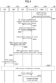
- FIG. 4 is a first sequence diagram showing an example of a flow of a data transmission procedure according to the embodiment of the present invention.
- FIG. 4 shows an example for the first AF 390-1.
- the DN 40 notifies the first AF 390-1 that a first user has approached the terminal 20 (step S201).
- the approach of the user is detected by a sensor included in the DN 40, a computer device connected to the sensor, and the like, and the user is specified as the first user by face authentication or the like.
- face authentication or the like.
- AF group occupation is designated as supplementary information.
- the supplementary information is specified as any one of AF session occupation, AF occupation, and AF group occupation.
- the PCF 360 transmits PDU session rule update information and PCC rule 1 to the SMF 370 (step S205).
- the PCC rule 1 is a rule that the gate state is set to "open" for the service data flow specified by the first AF 390-1 in the AF session establishment request.
- exclusive control is performed in the order from the locking to the selective release of the gate.
- the PCF 360 transmits an event notification to the first AF 390-1 (step S209).
- the first AF 390-1 transfers (transmits) the AF data to the terminal 20 (step S210).
- FIG. 5 is a second sequence diagram showing an example of the flow of the data transmission procedure according to the embodiment of the present invention.
- FIG. 5 shows an example for the second AF 390-2 after the procedure of FIG. 4 has been performed.
- the second AF 390-2 belongs to the same group (AFGx) as the first AF 390-1.
- the DN 40 notifies the second AF 390-2 that the first user has approached the terminal 20 (step S302).
- the approach of the user is detected by a sensor included in the DN 40, a computer device connected to the sensor, and the like, and the user is specified as the first user by face authentication or the like.
- Such a method of notifying of the approach is merely an example, and other methods may be used.
- the second AF 390-2 may determine that the first user has approached the terminal 20 by receiving the notification of step S301.
- AF group occupation is designated as supplementary information.
- the PCF 360 permits AF session establishment when the same user belonging to the occupying AF group approaches.
- the PCF 360 transmits PDU session rule update information and PCC rule 2 to the SMF 370 (step S306).
- the PCC rule 2 is a rule that the gate state is set to "open" for the service data flow specified by the second AF 390-2 in the AF session establishment request.
- the PCF 360 transmits an event notification to the second AF 390-2 (step S310).
- the second AF 390-2 transfers (transmits) AF data to the terminal 20 (step S311).
- FIG. 6 is a third sequence diagram showing an example of the flow of the data transmission procedure according to the embodiment of the present invention.
- FIG. 6 shows an example for the third AF 390-3 after the procedure of FIG. 5 has been performed. It is assumed that the third AF 390-3 does not belong to the same group (AFGx) as the first AF 390-1.
- the DN 40 notifies the third AF 390-3 that the first user has approached the terminal 20 (step S402).
- the approach of the user is detected by a sensor included in the DN 40, a computer device connected to the sensor, and the like, and the user is specified as the first user by face authentication or the like.
- face authentication or the like.
- AF occupation is specified as supplementary information.
- the PCF 360 rejects the AF session establishment if AF occupation is specified and the PDU session is in the AF group occupation (i.e., if the designated occupation type is different from the occupation type of the current occupation). Note that, when the AF group occupation is designated and the AF occupation of the PDU session is by a group different from the designated group, the PCF 360 may reject the AF session establishment.
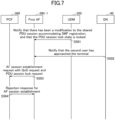
- FIG. 7 is a fourth sequence diagram showing an example of a flow of a data transmission procedure according to the embodiment of the present invention.
- FIG. 7 shows an example of a case where a second user different from the first user approaches the terminal 20 after the procedure of FIG. 5 or 6 is executed.
- the DN 40 notifies the first AF 390-1 that the second user has approached the terminal 20 (step S502).
- the approach of the user is detected by a sensor included in the DN 40, a computer device connected to the sensor, and the like, and the user is identified as the second user by face authentication or the like.
- face authentication or the like.
- AF group occupation is designated as supplementary information.
- the PCF 360 rejects the AF session establishment.
- the PCF 360 may reject the AF session establishment.
- FIG. 8 is a sequence diagram showing an example of the flow of the data transmission end procedure according to the embodiment of the present invention.
- the PCF 360 transmits PDU session rule update information and deletion instruction of the PCC rule 1 to the SMF 370 (step S602).
- the SMF 370 transmits a PFCP session modification request to the UPF 380 (step S603).
- the exclusive control is performed in the order from the closing of the corresponding gate to the change of the occupancy information related to the lock. Then, the PDU session modification is completed (step S605).
- step S602 the PCF 360 transmits PDU session rule update information and a deletion instruction of the PCC rule 2 to the SMF 370.
- the SMF 370 transmits a PFCP session modification request to the UPF 380.
- step S605 the PDU session modification is completed.
- the base station 10, the terminal 20, and various network nodes include functions for implementing the above-described embodiments. However, the base station 10, the terminal 20, and various network nodes may each include only some of the functions in the embodiments.
- FIG. 9 is a diagram illustrating an example of a functional configuration of the base station 10.
- the base station 10 includes a transmission unit 110, a reception unit 120, a configuration unit 130, and a control unit 140.
- the functional configuration shown in FIG. 9 is merely an example.
- the functional sections and the names of the functional units may be any as long as the operations according to the embodiment of the present invention can be performed.
- the network node may have the same functional configuration as the base station 10. Further, the network nodes having a plurality of different functions on the system architecture may be configured by a plurality of network nodes separated for each function.
- the transmission unit 110 includes a function of generating a signal to be transmitted to the terminal 20 or another network node and transmitting the signal in a wired or wireless manner.
- the reception unit 120 includes a function of receiving various signals transmitted from the terminal 20 or another network node and acquiring, for example, information of a higher layer from the received signal.
- the configuration unit 130 stores configuration information configured in advance and various kinds of configuration information to be transmitted to the terminal 20 in a storage apparatus, and reads the configuration information from the storage apparatus as necessary.
- the content of the configuration information is, for example, a configuration related to communication using NTN.
- the control unit 140 performs processing related to communication using NTN as described in the embodiment.
- the control unit 140 performs processing related to communication with the terminal 20.
- the control unit 140 performs a process related to the verification of the geographical position of the terminal 20.
- the functional unit related to signal transmission in the control unit 140 may be included in the transmission unit 110, and the functional unit related to signal reception in the control unit 140 may be included in the reception unit 120.
- FIG. 10 is a diagram illustrating an example of a functional configuration of the terminal 20.
- the terminal 20 includes a transmission unit 210, a reception unit 220, a configuration unit 230, and a control unit 240.
- the functional configuration shown in FIG. 10 is merely an example.
- the functional sections and the names of the functional units may be any as long as the operations according to the embodiment of the present invention can be performed.
- the USIM mounted on the terminal 20 may include the transmission unit 210, the reception unit 220, the configuration unit 230, and the control unit 240, similarly to the terminal 20.
- the transmission unit 210 creates a transmission signal from the transmission data and transmits the transmission signal by radio.
- the reception unit 220 receives various signals by radio and acquires a signal of a higher layer from the received signal of the physical layer. Also, the reception unit 220 has a function of receiving NR-PSS, NR-SSS, NR-PBCH, DL/UL control signals or reference signals, and so on transmitted from a network node.
- the configuration unit 230 stores various kinds of configuration information received from the network node by the receiving unit 220 in the storage apparatus, and reads the configuration information from the storage apparatus as necessary.
- the configuration unit 230 also stores configuration information configured in advance.
- the network node of the present embodiment may be configured as a network node described in each of the following items.
- the following communication method may be implemented.
- a network node including:
- the transmission unit transmits, to the other network node that controls an application, information indicating whether or not the PDU session is occupied by a network node, that controls an application, different from the other network node that controls an application.
- the transmission unit transmits, to the other network node that controls an application, information indicating whether or not the PDU session is occupied by a network node, that controls an application, belonging to a group different from a group that the other network node that controls an application belongs to.
- a communication method executed by a network node including:
- any of the above configurations provides a technique that enables appropriate exclusive control to be realized in a terminal shared by a plurality of users in a radio communication system.
- a notification indicating the occurrence of the event can be transmitted to another network node.
- each of the function blocks may be attained by using one apparatus that is physically or logically coupled, by directly or indirectly (for example, in a wired manner, over the radio, or the like) connecting two or more apparatuses that are physically or logically separated and by using such a plurality of apparatuses.
- the function block may be attained by combining one apparatus described above or a plurality of apparatuses described above with software.
- the function includes determining, judging, calculating, computing, processing, deriving, investigating, looking up, ascertaining, receiving, transmitting, output, accessing, resolving, selecting, choosing, establishing, comparing, assuming, expecting, presuming, broadcasting, notifying, communicating, forwarding, configuring, reconfiguring, allocating (mapping), assigning, and the like, but is not limited thereto.
- a function block (a configuration part) that functions to transmit is referred to as a transmitting unit or a transmitter.
- the attainment method thereof is not particularly limited.
- the network node, the terminal 20, and the like in one embodiment of this disclosure may function as a computer for performing the processing of a radio communication method of this disclosure.
- FIG. 11 is a diagram illustrating an example of a hardware configuration of the base station 10 and the terminal 20 according to one embodiment of this disclosure.
- the network node may have a hardware configuration similar to that of the base station 10.
- the USIM may have the same hardware configuration as the terminal 20.
- the base station 10 and the terminal 20 described above may be physically configured as a computer apparatus including a processor 1001, a storage 1002, an auxiliary storage 1003, a communication apparatus 1004, an input apparatus 1005, an output apparatus 1006, a bus 1007, and the like.
- the word “apparatus” can be replaced with a circuit, a device, a unit, or the like.
- the hardware configuration of the base station 10 and the terminal 20 may be configured to include one or a plurality of apparatuses illustrated in the drawings, or may be configured not to include a part of the apparatuses.
- Each function of the base station 10 and the terminal 20 is attained by reading predetermined software (a program) on hardware such as the processor 1001 and the storage 1002 such that the processor 1001 performs an operation, and by controlling the communication of the communication apparatus 1004 or by controlling at least one of reading and writing of data in the storage 1002 and the auxiliary storage 1003.
- predetermined software a program
- the communication apparatus 1004 or by controlling at least one of reading and writing of data in the storage 1002 and the auxiliary storage 1003.
- the processor 1001 controls the entire computer by operating an operating system.
- the processor 1001 may be configured by a central processing unit (CPU) including an interface with respect to the peripheral equipment, a control apparatus, an operation apparatus, a register, and the like.
- CPU central processing unit
- the control unit 140, the control unit 240, or the like, described above, may be attained by the processor 1001.
- the processor 1001 reads out a program (a program code), a software module, data, and the like to the storage 1002 from at least one of the auxiliary storage 1003 and the communication apparatus 1004, and thus, executes various processing.
- a program for allowing a computer to execute at least a part of the operation described in the embodiment described above is used as the program.
- the control unit 140 of the base station 10 shown in FIG. 9 may be attained by a control program that is stored in the storage 1002 and is operated by the processor 1001.
- the control unit 240 of the terminal 20 shown in FIG. 10 may be attained by a control program that is stored in the storage 1002 and is operated by the processor 1001.
- the various types of processing described above are executed by one processor 1001, but the various types of processing may be simultaneously or sequentially executed by two or more processors 1001.
- the processor 1001 may be mounted on one or more chips.
- the program may be transmitted from a network through an electric communication line.
- the storage 1002 is a computer readable recording medium, and for example, may be configured of at least one of a read only memory (ROM), an erasable programmable ROM (EPROM), an electrically erasable programmable ROM (EEPROM), a random access memory (RAM), or the like.
- the storage 1002 may be referred to as a register, a cache, a main memory (a main storage unit), and the like.
- the storage 1002 is capable of retaining a program (a program code), a software module, and the like that can be executed in order to implement a communication method according to one embodiment of this disclosure.
- the auxiliary storage 1003 is a computer readable recording medium, and for example, may be configured of at least one of an optical disk such as a compact disc ROM (CD-ROM), a hard disk drive, a flexible disk, a magnetooptical disk (for example, a compact disc, a digital versatile disk, and a Blu-ray (Registered Trademark) disc), a smart card, a flash memory (for example, a card, a stick, a key drive), a floppy (Registered Trademark) disk, a magnetic strip, or the like.
- the storage medium described above may be a database including at least one of the storage device 1002 and the auxiliary storage device 1003, a server, or a suitable medium.
- the communication apparatus 1004 is hardware (a transmitting and receiving device) for performing communication with respect to the computer through at least one of a wire network and a radio network, and for example, is also referred to as a network device, a network controller, a network card, a communication module, and the like.
- the communication device 1004, for example, may be configured by including a high frequency switch, a duplexer, a filter, a frequency synthesizer, and the like, in order to attain at least one of frequency division duplex (FDD) and time division duplex (TDD).
- FDD frequency division duplex
- TDD time division duplex
- a transmitting and receiving antenna, an amplifier, a transmitting and receiving unit, a transmission path interface, and the like may be attained by the communication apparatus 1004.
- the transmitting unit and the receiving unit may be mounted while being physically or logically separated.
- the input apparatus 1005 is an input device for receiving input from the outside (for example, a keyboard, a mouse, a microphone, a switch, a button, a sensor, and the like).
- the output apparatus 1006 is an output device for implementing output with respect to the outside (for example, a display, a speaker, an LED lamp, and the like). Note that the input apparatus 1005 and the output apparatus 1006 may be integrally configured (for example, a touch panel).
- each of the apparatuses such as the processor 1001 and the storage 1002 may be connected by the bus 1007 for performing communication with respect to information.
- the bus 1007 may be configured by using a single bus, or may be configured by using different buses for each of the apparatuses.
- the base station 10 and the terminal 20 may be configured by including hardware such as a microprocessor, a digital signal processor (DSP), an application specific integrated circuit (ASIC), a programmable logic device (PLD), and a field programmable gate array (FPGA), and a part or all of the respective function blocks may be attained by the hardware.
- the processor 1001 may be implemented by using at least one piece of hardware.
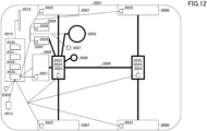
- FIG. 12 shows a configuration example of a vehicle 2001 according to the present embodiment.
- the vehicle 2001 includes a drive unit 2002, a steering unit 2003, an accelerator pedal 2004, a brake pedal 2005, a shift lever 2006, front wheels 2007, rear wheels 2008, an axle 2009, an electronic control unit 2010, various sensors 2021-2029, an information service unit 2012, and a communication module 2013.
- a communication apparatus mounted on the vehicle 2001, and may be applied to, for example, the communication module 2013.
- the electronic control unit 2010 includes a microprocessor 2031, a memory (ROM, RAM) 2032, and a communication port (IO port) 2033.
- the electronic control unit 2010 receives signals from the various sensors 2021-2029 provided in the vehicle 2001.
- the electronic control unit 2010 may be referred to as an ECU (Electronic Control Unit).
- the signals from the various sensors 2021 to 2029 include a current signal from a current sensor 2021 which senses the current of the motor, a front or rear wheel rotation signal acquired by a revolution sensor 2022, a front or rear wheel pneumatic signal acquired by a pneumatic sensor 2023, a vehicle speed signal acquired by a vehicle speed sensor 2024, an acceleration signal acquired by an acceleration sensor 2025, an accelerator pedal depression signal acquired by an accelerator pedal sensor 2029, a brake pedal depression signal acquired by a brake pedal sensor 2026, an operation signal of a shift lever acquired by a shift lever sensor 2027, and a detection signal, acquired by the object detection sensor 2028, for detecting an obstacle, a vehicle, a pedestrian, and the like.
- the information service unit 2012 includes various devices for providing various kinds of information such as driving information, traffic information, and entertainment information, including a car navigation system, an audio system, a speaker, a television, and a radio, and one or more ECUs controlling these devices.
- the information service unit 2012 provides various types of multimedia information and multimedia services to the occupants of the vehicle 2001 by using information obtained from the external device through the communication module 2013 or the like.
- the information service unit 2012 may include an input device (for example, a keyboard, a mouse, a microphone, a switch, a button, a sensor, a touch panel, or the like) that receives an input from the outside, and may include an output device (for example, a display, a speaker, an LED lamp, a touch panel, or the like) that performs an output to the outside.
- an input device for example, a keyboard, a mouse, a microphone, a switch, a button, a sensor, a touch panel, or the like
- an output device for example, a display, a speaker, an LED lamp, a touch panel, or the like
- a driving support system unit 2030 includes: various devices for providing functions of preventing accidents and reducing driver's operating loads such as a millimeter wave radar, a LiDAR (Light Detection and Ranging), a camera, a positioning locator (e.g., GNSS, etc.), map information (e.g., high definition (HD) map, autonomous vehicle (AV) map, etc.), a gyro system (e.g., IMU (Inertial Measurement Unit), INS (Inertial Navigation System), etc.), an AI (Artificial Intelligence) chip, an AI processor; and one or more ECUs controlling these devices.
- the driving support system unit 2030 transmits and receives various types of information via the communication module 2013 to realize a driving support function or an autonomous driving function.
- the communication module 2013 may communicate with the microprocessor 2031 and components of the vehicle 2001 via a communication port.
- the communication module 2013 transmits and receives data via the communication port 2033, to and from the drive unit 2002, the steering unit 2003, the accelerator pedal 2004, the brake pedal 2005, the shift lever 2006, the front wheels 2007, the rear wheels 2008, the axle 2009, the microprocessor 2031 and the memory (ROM, RAM) 2032 in the electronic control unit 2010, and sensors 2021-2029 provided in the vehicle 2001.
- the communication module 2013 is a communication device that can be controlled by the microprocessor 2031 of the electronic control unit 2010 and that is capable of communicating with external devices. For example, various kinds of information are transmitted to and received from external devices through radio communication.
- the communication module 2013 may be internal to or external to the electronic control unit 2010.
- the external devices may include, for example, a base station, a mobile station, or the like.
- the communication module 2013 receives various types of information (traffic information, signal information, inter-vehicle information, etc.) transmitted from the external devices and displays the received information on the information service unit 2012 provided in the vehicle 2001.
- the information service unit 2012 may be referred to as an output unit that outputs information (for example, outputs information to a device such as a display or a speaker based on PDSCH (or data/information decoded from the PDSCH) received by the communication module 2013).
- the communication module 2013 stores the various types of information received from the external devices in the memory 2032 available to the microprocessor 2031. Based on the information stored in the memory 2032, the microprocessor 2031 may control the drive unit 2002, the steering unit 2003, the accelerator pedal 2004, the brake pedal 2005, the shift lever 2006, the front wheels 2007, the rear wheels 2008, the axle 2009, the sensors 2021-2029, etc., mounted in the vehicle 2001.
- the operations of a plurality of functional parts may be physically performed by one component, or the operation of one functional part may be physically performed by a plurality of components.
- a processing procedure described in the embodiment a processing order may be changed, insofar as there is no contradiction.
- the base station 10 and the terminal 20 have been described by using a functional block diagram, but such an apparatus may be attained by hardware, software, or a combination thereof.
- Each of software that is operated by a processor of the base station 10 according to the embodiment of the invention and software that is operated by a processor of the terminal 20 according to the embodiment of the invention may be retained in a random access memory (RAM), a flash memory, a read only memory (ROM), an EPROM, an EEPROM, a register, a hard disk (HDD), a removable disk, a CD-ROM, a database, a server, and other suitable recording media.
- RAM random access memory
- ROM read only memory
- EPROM an EPROM
- EEPROM electrically erasable programmable read-only memory
- register a register
- HDD hard disk
- CD-ROM compact disc-read only memory
- database a database
- server and other suitable recording media.
- the notification of the information is not limited to the aspect/embodiment described in this disclosure, and may be performed by using other methods.
- the notification of the information may be implemented by physical layer signaling (for example, downlink control information (DCI) and uplink control information (UCI)), higher layer signaling (for example, radio resource control (RRC) signaling, medium access control (MAC) signaling, broadcast information (a master information block (MIB)), a system information block (SIB)), other signals, or a combination thereof.
- the RRC signaling may be referred to as an RRC message, and for example, may be an RRC connection setup message, an RRC connection reconfiguration message, and the like.
- LTE long term evolution
- LTE-A LTE-advanced
- SUPER 3G IMT-advanced
- 4G 4th generation mobile communication system
- 5G 5th generation mobile communication system
- 6G 6th generation mobile communication system
- xG x is an integer or a decimal for example
- future radio access FAA
- new radio NR
- New radio access NX
- Future generation radio access FX
- W-CDMA Registered Trademark
- GSM Registered Trademark
- CDMA2000 an ultra mobile broadband
- UMB ultra mobile broadband
- IEEE 802.11 Wi-Fi (Registered Trademark)
- IEEE 802.16 WiMAX (Registered Trademark)
- IEEE 802.20 an ultra-wideband (UWB), Bluetooth (Registered Trademark), and other suitable systems and a next-generation system that is expanded, modified, created, or defined on the basis thereof.
- UMB ultra mobile broadband
- Wi-Fi Wi-Fi
- IEEE 802.16 WiMAX (Registered Trademark)
- a specific operation that is performed by the base station 10 may be performed by an upper node, in accordance with a case.
- various operations that are performed in order for communication with respect to the terminal 20 can be performed by at least one of the base station 10 and network nodes other than the base station 10 (for example, MME, S-GW, or the like is considered as the network node, but the network node is not limited thereto).
- MME Mobility Management Entity
- S-GW Serving Mobility Management Entity
- the information, the signal, or the like described in this disclosure can be output to a lower layer (or the higher layer) from the higher layer (or the lower layer).
- the information, the signal, or the like may be input and output through a plurality of network nodes.
- the information or the like that is input and output may be retained in a specific location (for example, a memory), or may be managed by using a management table.
- the information or the like that is input and output can be subjected to overwriting, updating, or editing.
- the information or the like that is output may be deleted.
- the information or the like that is input may be transmitted to the other apparatuses.
- Judgment in this disclosure may be performed by a value represented by 1 bit (0 or 1), may be performed by a truth-value (Boolean: true or false), or may be performed by a numerical comparison (for example, a comparison with a predetermined value).
- the software should be broadly interpreted to indicate a command, a command set, a code, a code segment, a program code, a program, a sub-program, a software module, an application, a software application, a software package, a routine, a sub-routine, an object, an executable file, an execution thread, a procedure, a function, and the like.
- software, a command, information, and the like may be transmitted and received through a transmission medium.
- a transmission medium a coaxial cable, an optical fiber cable, a twisted pair, a digital subscriber line (DSL), and the like
- a radio technology an infrared ray, a microwave, and the like
- the information, the signal, and the like described in this disclosure may be represented by using any of various different technologies.
- the data, the command, the information, the signal, the bit, the symbol, the chip, and the like that can be referred to through the entire description above may be represented by a voltage, a current, an electromagnetic wave, a magnetic field or magnetic particles, an optical field or a photon, or an arbitrary combination thereof.
- the terms described in this disclosure and the terms necessary for understanding this disclosure may be replaced with terms having the same or similar meaning.
- at least one of the channel and the symbol may be a signal (signaling).
- the signal may be a message.
- a component carrier (CC) may be referred to as a carrier frequency, a cell, a frequency carrier, and the like.
- system and "network” used in this disclosure are interchangeably used.
- the information, the parameter, and the like described in this disclosure may be represented by using an absolute value, may be represented by using a relative value from a predetermined value, or may be represented by using another corresponding piece of information.
- a radio resource may be indicated by an index.
- base station radio base station
- base station fixed station
- NodeB nodeB
- eNodeB eNodeB
- gNodeB gNodeB
- the base station is capable of accommodating one or a plurality of (for example, three) cells.
- the entire coverage area of the base station can be classified into a plurality of small areas, and each of the small areas is capable of providing communication service by a base station sub-system (for example, an indoor type small base station (a remote radio head (RRH)).
- a base station sub-system for example, an indoor type small base station (a remote radio head (RRH)
- RRH remote radio head
- the term "cell” or “sector” indicates a part of the coverage area or the entire coverage area of at least one of the base station and the base station sub-system that perform the communication service in the coverage.
- the transmission of information from the base station to the terminal may be read as the base station instructing the terminal to perform control and operation based on the information.
- MS mobile station
- UE user equipment
- terminal terminal
- the mobile station may be referred to as a subscriber station, a mobile unit, a subscriber unit, a wireless unit, a remote unit, a mobile device, a wireless device, a wireless communication device, a remote device, a mobile subscriber station, an access terminal, a mobile terminal, a wireless terminal, a remote terminal, a handset, a user agent, a mobile client, a client, or other suitable terms, by a person skilled in the art.
- At least one of the base station and the mobile station may be referred to as a transmission device, a reception device, a communication device, or the like. At least one of the base station and the mobile station may be a device mounted on a mobile object, the mobile object itself, or the like.
- the mobile object is a movable object, and the moving speed is arbitrary. The moving object may be stopped.
- Examples of the moving object include, but are not limited to, vehicles, transportation vehicles, automobiles, motorcycles, bicycles, connected cars, excavators, bulldozers, wheel loaders, dump trucks, forklifts, trains, buses, rear cars, rickshaws, ships and other watercraft, airplanes, rockets, artificial satellites, drones, multicopters, quadcopters, balloons, and objects mounted thereon.
- the mobile object may be a vehicle (for example, a car, an airplane, and the like), may be a mobile object that is moved in an unmanned state (for example, a drone, an autonomous driving car, and the like), or may be a (manned or unmanned) robot.
- the base station in this disclosure may be replaced with the terminal.
- each aspect/embodiment of this disclosure may be applied to a configuration in which communication between the base station and the user terminal is replaced with communication in a plurality of terminals 20 (for example, may be referred to as device-to-device (D2D), vehicle-to-everything (V2X), and the like).
- the function of the base station 10 described above may be provided in the terminal 20.
- the words "uplink”, “downlink”, and the like may be replaced with words corresponding to the communication between the terminals (for example, "side”).
- an uplink channel, a downlink channel, and the like may be replaced with a side channel.
- the user terminal in this disclosure may be replaced with the base station.
- the function of the user terminal described above may be provided in the base station.
- two elements are "connected” or “coupled” to each other by using at least one of one or more electric wires, cables, and print electric connection, and as some non-limiting and non-inclusive examples, by using electromagnetic energy having a wavelength of a radio frequency domain, a microwave domain, and an optical (visible and invisible) domain, and the like.
- any reference to elements using the designations "first,” “second,” and the like, used in this disclosure, does not generally limit the amount or the order of such elements. Such designations can be used in this disclosure as a convenient method for discriminating two or more elements. Therefore, a reference to a first element and a second element does not indicate that only two elements can be adopted or that the first element necessarily precedes the second element in any manner.
- a radio frame may be configured of one or a plurality of frames in a time domain.
- Each of one or a plurality of frames in the time domain may be referred to as a subframe.
- the subframe may be further configured of one or a plurality of slots in the time domain.
- the subframe may be a fixed time length (for example, 1 ms) that does not depend on numerology.
- the numerology may be a communication parameter to be applied to at least one of the transmission and the reception of a certain signal or channel.
- the numerology may indicate at least one of subcarrier spacing (SCS), a bandwidth, a symbol length, a cyclic prefix length, a transmission time interval (TTI), the number of symbols per TTI, a radio frame configuration, specific filtering processing that is performed by the transceiver in a frequency domain, specific windowing processing that is performed by the transceiver in a time domain, and the like.
- SCS subcarrier spacing
- TTI transmission time interval
- the slot may be configured of one or a plurality of symbols (an orthogonal frequency division multiplexing (OFDM) symbol, a single carrier frequency division multiple access (SC-FDMA) symbol, and the like) in a time domain.
- the slot may be time unit based on the numerology.
- the slot may include a plurality of mini slots. Each of the mini slots may be configured of one or a plurality of symbols in the time domain. In addition, the mini slot may be referred to as a subslot. The mini slot may be configured of symbols of which the number is less than that of the slot.
- PDSCH (or PUSCH) to be transmitted in time units greater than the mini slot may be referred to as a PDSCH (or PUSCH) mapping type A .
- PDSCH (or PUSCH) to be transmitted by using the mini slot may be referred to as a PDSCH (or PUSCH) mapping type B.
- All of the radio frame, the subframe, the slot, the mini slot, and the symbol represent time units at the time of transmitting a signal.
- Other names respectively corresponding to the radio frame, the subframe, the slot, the mini slot, and the symbol may be used.
- one subframe may be referred to as a transmission time interval (TTI), a plurality of consecutive subframes may be referred to as TTI, or one slot or one mini slot may be referred to as TTI. That is, at least one of the subframe and TTI may be a subframe (1 ms) in the existing LTE, may be a period shorter than 1 ms (for example, 1 to 13 symbols), or may be a period longer than 1 ms. Note that, a unit representing TTI may be referred to as a slot, a mini slot, and the like, but not a subframe.
- TTI indicates a minimum time unit of scheduling in radio communication.
- the base station performs scheduling for allocating a radio resource (a frequency bandwidth, transmission power, and the like that can be used in each of the terminals 20) in TTI units, with respect to each of the terminals 20.
- a radio resource a frequency bandwidth, transmission power, and the like that can be used in each of the terminals 20.
- the definition of TTI is not limited thereto.
- TTI may be a transmission time unit of a data packet (a transport block), a code block, a codeword, and the like that are subjected to channel coding, or may be processing unit of scheduling, link adaptation, and the like. Note that, when TTI is applied, a time section (for example, the number of symbols) in which the transport block, the code block, the codeword, and the like are actually mapped may be shorter than TTI.
- one or more TTIs may be the minimum time unit of the scheduling.
- the number of slots (the number of mini slots) configuring the minimum time unit of the scheduling may be controlled.
- TTI having a time length of 1 ms may be referred to as a normal TTI (TTI in LTE Rel.8-12), a normal TTI, a long TTI, a normal subframe, a normal subframe, a long subframe, a slot, and the like.
- TTI shorter than the normal TTI may be referred to as a shortened TTI, a short TTI, a partial TTI (or a fractional TTI), a shortened subframe, a short subframe, a mini slot, a subslot, a slot, and the like.
- the long TTI (for example, the normal TTI, the subframe, and the like) may be replaced with TTI having a time length of greater than or equal to 1 ms
- the short TTI (for example, the shortened TTI and the like) may be replaced with TTI having a TTI length of less than a TTI length of the long TTI and greater than or equal to 1 ms.
- the resource block (RB) is a resource allocation unit of the time domain and the frequency domain, and may include one or a plurality of consecutive subcarriers in the frequency domain.
- the number of subcarriers included in RB may be the same regardless of the numerology, or for example, may be 12.
- the number of subcarriers included in RB may be determined based on the numerology.
- the time domain of RB may include one or a plurality of symbols, or may be the length of one slot, one mini slot, one subframe, or one TTI.
- One TTI, one subframe, and the like may be respectively configured of one or a plurality of resource blocks.
- one or a plurality of RBs may be referred to as a physical resource block (physical RB: PRB), a sub-carrier group (SCG), a resource element group (REG), a PRB pair, an RB pair, and the like.
- PRB physical resource block
- SCG sub-carrier group
- REG resource element group
- PRB pair an RB pair, and the like.
- the resource block may be configured of one or a plurality of resource elements (RE).
- RE resource elements
- one RE may be a radio resource domain of one subcarrier and one symbol.
- a bandwidth part (may be referred to as a part bandwidth or the like) may represent a subset of consecutive common resource blocks (common RBs) for certain numerology, in a certain carrier.
- the common RB may be specified by an index of RB based on a common reference point of the carrier.
- PRB may be defined by a certain BWP, and may be numbered within BWP.
- BWP may include BWP for UL (UL BWP) and BWP for DL (DL BWP).
- UL BWP UL BWP
- DL BWP DL BWP
- one or a plurality of BWPs may be configured within one carrier.
- At least one of the configured BWPs may be active, and it need not be assumed that the terminal 20 transmits and receives a predetermined signal/channel out of the active BWP.
- the "cell”, the “carrier”, and the like in this disclosure may be replaced with "BWP”.
- the structure of the radio frame, the subframe, the slot, the mini slot, the symbol, and the like, described above, is merely an example.
- the configuration of the number of subframes included in the radio frame, the number of slots per a subframe or a radio frame, the number of mini slots included in the slot, the number of symbols and RBs included in the slot or a mini slot, the number of subcarriers included in RB, the number of symbols in TTI, a symbol length, a cyclic prefix (CP) length, and the like can be variously changed.
- this disclosure may include a case where nouns following the articles are plural.
- the term "A and B are different” may indicate “A and B are different from each other”. Note that, the term may indicate “A and B are respectively different from C”.
- the terms "separated”, “coupled”, and the like may be interpreted as with "being different”.
- each aspect/embodiment described in this disclosure may be independently used, may be used by being combined, or may be used by being switched in accordance with execution.
- the notification of predetermined information (for example, the notification of "being X") is not limited to being performed explicitly, and may be performed implicitly (for example, the notification of the predetermined information is not performed).
Landscapes
- Engineering & Computer Science (AREA)
- Computer Networks & Wireless Communication (AREA)
- Signal Processing (AREA)
- Computer Security & Cryptography (AREA)
- Databases & Information Systems (AREA)
- Mobile Radio Communication Systems (AREA)
Applications Claiming Priority (1)
| Application Number | Priority Date | Filing Date | Title |
|---|---|---|---|
| PCT/JP2022/020295 WO2023218671A1 (fr) | 2022-05-13 | 2022-05-13 | Nœud de réseau et procédé de communication |
Publications (2)
| Publication Number | Publication Date |
|---|---|
| EP4525552A1 true EP4525552A1 (fr) | 2025-03-19 |
| EP4525552A4 EP4525552A4 (fr) | 2025-12-31 |
Family
ID=88729901
Family Applications (1)
| Application Number | Title | Priority Date | Filing Date |
|---|---|---|---|
| EP22941747.2A Pending EP4525552A4 (fr) | 2022-05-13 | 2022-05-13 | Noeud de réseau et procédé de communication |
Country Status (5)
| Country | Link |
|---|---|
| US (1) | US20250310747A1 (fr) |
| EP (1) | EP4525552A4 (fr) |
| JP (1) | JP7826466B2 (fr) |
| CN (1) | CN119156888A (fr) |
| WO (1) | WO2023218671A1 (fr) |
Family Cites Families (4)
| Publication number | Priority date | Publication date | Assignee | Title |
|---|---|---|---|---|
| JP2020530703A (ja) * | 2017-08-11 | 2020-10-22 | コンヴィーダ ワイヤレス, エルエルシー | 通信ネットワークにおけるネットワークデータ分析 |
| US11382145B2 (en) * | 2018-08-06 | 2022-07-05 | Huawei Technologies Co., Ltd. | Systems and methods to support group communications |
| EP3737151B1 (fr) * | 2019-05-06 | 2023-07-19 | Ntt Docomo, Inc. | Dispositif de réseau central de communication mobile et procédé de gestion de communications sans fil après l'insertion d'une fonction de gestion de session intermédiaire |
| KR20210030167A (ko) * | 2019-09-09 | 2021-03-17 | 삼성전자주식회사 | 무선 통신 시스템에서 하나의 단말을 여러 사용자가 이용하기 위한 방법 및 장치 |
-
2022
- 2022-05-13 US US18/863,147 patent/US20250310747A1/en active Pending
- 2022-05-13 EP EP22941747.2A patent/EP4525552A4/fr active Pending
- 2022-05-13 JP JP2024520241A patent/JP7826466B2/ja active Active
- 2022-05-13 WO PCT/JP2022/020295 patent/WO2023218671A1/fr not_active Ceased
- 2022-05-13 CN CN202280095868.7A patent/CN119156888A/zh active Pending
Also Published As
| Publication number | Publication date |
|---|---|
| JP7826466B2 (ja) | 2026-03-09 |
| WO2023218671A1 (fr) | 2023-11-16 |
| EP4525552A4 (fr) | 2025-12-31 |
| CN119156888A (zh) | 2024-12-17 |
| JPWO2023218671A1 (fr) | 2023-11-16 |
| US20250310747A1 (en) | 2025-10-02 |
Similar Documents
| Publication | Publication Date | Title |
|---|---|---|
| WO2024062583A1 (fr) | Nœud de réseau et procédé de communication | |
| WO2023223512A1 (fr) | Nœud de réseau et procédé de communication | |
| WO2024062582A1 (fr) | Nœud de réseau, système de communication, et procédé de communication | |
| WO2024057549A1 (fr) | Nœud de réseau et procédé de communication | |
| WO2023223511A1 (fr) | Nœud de réseau et procédé de communication | |
| EP4525552A1 (fr) | Noeud de réseau et procédé de communication | |
| WO2024034074A1 (fr) | Nœud de réseau, système de réseau central et procédé de commande | |
| EP4525547A1 (fr) | Noeud de réseau et procédé de communication | |
| EP4642098A1 (fr) | Dispositif de noeud de réseau et procédé de communication | |
| EP4642069A1 (fr) | Dispositif de noeud de réseau, système de communication, et procédé de communication | |
| EP4679879A1 (fr) | Terminal, dispositif de noeud de réseau et procédé de communication | |
| JP7836389B2 (ja) | ネットワークノード、無線通信システム及び通信方法 | |
| EP4615075A1 (fr) | Noeud de réseau et procédé de communication | |
| EP4550925A1 (fr) | Noeud de réseau, station de base et procédé de communication | |
| WO2024004160A1 (fr) | Nœud de réseau et procédé de communication | |
| WO2024034135A1 (fr) | Nœud de réseau et procédé d'autorisation | |
| WO2024034075A1 (fr) | Station de base, terminal, nœud de réseau et procédé de communication | |
| WO2024057550A1 (fr) | Nœud réseau, système de communication, et procédé de communication | |
| WO2025088814A1 (fr) | Terminal, station de base et procédé de communication | |
| WO2023195111A1 (fr) | Nœud de réseau et procédé de communication | |
| WO2024038483A1 (fr) | Nœud réseau et procédé de commande de synchronisation | |
| WO2026033814A1 (fr) | Station de base et terminal | |
| WO2024033986A1 (fr) | Station de base et procédé de communication | |
| WO2024100905A1 (fr) | Terminal, station de base et procédé de communication | |
| WO2025032835A1 (fr) | Terminal et procédé de communication |
Legal Events
| Date | Code | Title | Description |
|---|---|---|---|
| STAA | Information on the status of an ep patent application or granted ep patent |
Free format text: STATUS: THE INTERNATIONAL PUBLICATION HAS BEEN MADE |
|
| PUAI | Public reference made under article 153(3) epc to a published international application that has entered the european phase |
Free format text: ORIGINAL CODE: 0009012 |
|
| STAA | Information on the status of an ep patent application or granted ep patent |
Free format text: STATUS: REQUEST FOR EXAMINATION WAS MADE |
|
| 17P | Request for examination filed |
Effective date: 20241203 |
|
| AK | Designated contracting states |
Kind code of ref document: A1 Designated state(s): AL AT BE BG CH CY CZ DE DK EE ES FI FR GB GR HR HU IE IS IT LI LT LU LV MC MK MT NL NO PL PT RO RS SE SI SK SM TR |
|
| DAV | Request for validation of the european patent (deleted) | ||
| DAX | Request for extension of the european patent (deleted) | ||
| A4 | Supplementary search report drawn up and despatched |
Effective date: 20251201 |
|
| RIC1 | Information provided on ipc code assigned before grant |
Ipc: H04W 80/10 20090101AFI20251125BHEP Ipc: H04W 12/08 20210101ALI20251125BHEP |