EP4527232A1 - Chaussure de ski - Google Patents
Chaussure de ski Download PDFInfo
- Publication number
- EP4527232A1 EP4527232A1 EP24202407.3A EP24202407A EP4527232A1 EP 4527232 A1 EP4527232 A1 EP 4527232A1 EP 24202407 A EP24202407 A EP 24202407A EP 4527232 A1 EP4527232 A1 EP 4527232A1
- Authority
- EP
- European Patent Office
- Prior art keywords
- shaft part
- upper shaft
- ski boot
- tension
- actuating
- Prior art date
- Legal status (The legal status is an assumption and is not a legal conclusion. Google has not performed a legal analysis and makes no representation as to the accuracy of the status listed.)
- Pending
Links
Images




Classifications
-
- A—HUMAN NECESSITIES
- A43—FOOTWEAR
- A43B—CHARACTERISTIC FEATURES OF FOOTWEAR; PARTS OF FOOTWEAR
- A43B5/00—Footwear for sporting purposes
- A43B5/04—Ski or like boots
- A43B5/0427—Ski or like boots characterised by type or construction details
- A43B5/0429—Adjustment of the boot to calf or shin, i.e. fibula, tibia
-
- A—HUMAN NECESSITIES
- A43—FOOTWEAR
- A43B—CHARACTERISTIC FEATURES OF FOOTWEAR; PARTS OF FOOTWEAR
- A43B5/00—Footwear for sporting purposes
- A43B5/04—Ski or like boots
-
- A—HUMAN NECESSITIES
- A43—FOOTWEAR
- A43C—FASTENINGS OR ATTACHMENTS OF FOOTWEAR; LACES IN GENERAL
- A43C11/00—Other fastenings specially adapted for shoes
- A43C11/14—Clamp fastenings, e.g. strap fastenings; Clamp-buckle fastenings; Fastenings with toggle levers
-
- A—HUMAN NECESSITIES
- A43—FOOTWEAR
- A43C—FASTENINGS OR ATTACHMENTS OF FOOTWEAR; LACES IN GENERAL
- A43C11/00—Other fastenings specially adapted for shoes
- A43C11/16—Fastenings secured by wire, bolts, or the like
- A43C11/165—Fastenings secured by wire, bolts, or the like characterised by a spool, reel or pulley for winding up cables, laces or straps by rotation
Definitions
- the invention relates to a ski boot, in particular an alpine ski boot, comprising an outer shell having a lower shell part designed for connection to a ski binding and intended for receiving a foot, and an upper shaft part which is hingedly connected to the lower shell part and is intended for receiving a lower leg, wherein a distal and a medial end section of the upper shaft part are arranged at least partially overlapping in a use position and, in the use position, the distal end section is arranged inwardly and the medial end section is arranged outwardly, and the upper shaft part has an upper tensioning device which comprises a linear tension element and an actuating element for tensioning the linear tension element, wherein one actuating element is arranged on the distal end section of the upper shaft part, wherein the linear tension element has at least one free end which is connected to the actuating element in such a way that it is moved upon activation of the actuating element, so that the tension element can be transferred between a tensioned state and a non-tensioned state of the
- Ski boots are specially designed boots for alpine, touring, telemark, and cross-country skiing. They are constructed to provide a stable connection between skier and ski.
- the closure system of ski boots has evolved over the years.
- Most modern ski boots use buckles to close the outer shell.
- the outer shell usually contains an inner bootie, which provides comfort, support, and thermal insulation within the outer shell.
- Conventional alpine ski boots typically have one or two buckles, usually two, on the upper shaft and one to three buckles, usually two, on the lower shell. Such buckles work with a lever mechanism, allowing the skier to tighten the shell of the ski boot tightly around the foot and lower leg.
- the lever arm of the buckle is opened, the buckle is inserted into a notch, and then the lever arm is closed to achieve the desired tension.
- the A wide Velcro fastener may be provided at the top of the ski boot. Properly closing the ski boot is important for good power transfer to the ski and for the skier's safety. A well-fitting ski boot not only provides better control over the skis but also minimizes the risk of injury.
- Ski boots are also already known which have twist locks instead of conventional buckles, over which a linear tension element, i.e. a rope or wire-shaped tension element, can be tightened.
- a linear tension element i.e. a rope or wire-shaped tension element
- Ski boots which have a closing device for an upper shaft section or a cuff with a rope and a rotary fastener for tensioning and releasing the rope.
- Two different designs are shown here, whereby in the first variant the rope is fixedly attached to the cuff at one end and the other end can be tensioned and released using the rotary mechanism. In the second variant, however, the rope for tensioning and releasing is attached at both ends to the rotary wheel.
- it is sometimes necessary to open the cuff completely i.e. to move the end sections which overlap in the use position into a non-overlapping position, which is why a relatively long rope is required.
- the first design variant also has the disadvantage that the rotary wheel must be turned many times to tension the long rope accordingly.
- one embodiment features two holding elements to which two guide elements can be attached. If a user now wants to get in or out of the shoe, these guide elements must be removed or picked up from the holding elements. However, especially when closing the shoe, when they are picked up, the user needs both hands to prevent tangling.
- a ski boot according to claim 1 it is particularly provided that, in a non-tensioned state, the tension element can be removed from the upper shaft part without tools, so that the upper shaft part can be transferred from a use position into an open position in which the end sections can be transferred into a non-overlapping open position.
- a particularly advantageous guidance of the linear tension element can be achieved, in which the guide element, together with the tension element accommodated therein, can be removed from the distal end, wherein, however, a permanent connection between the distal end section of the shaft part and the tension element remains via the connection between the actuating element and the tension element even after the guide element has been removed from the distal end section of the shaft part, so that the risk of a tension element that has been completely detached from the distal end section becoming tangled is significantly reduced.
- a linear tension element is understood to mean, in particular, rope- or wire-shaped tension elements that have an elongated, particularly cylindrical shape and are suitable for transmitting a tensile or tensioning force and are flexible, so that they can be guided via rollers, Deflection pulleys or winches can be guided.
- the tension element is particularly preferably a lightweight wire rope, in particular made of stainless steel or another durable fiber, as is usually used in BOA® twist fasteners.
- the guide element is an element that is stiffer than the tension element and defines the course of the tension element in the connection area between the guide element and the tension element.
- the guide element has an at least preferably partially closed guide channel in which the tension element is slidably received.
- the guide element can advantageously be made of plastic, such as polyamide 6, glass fiber reinforced polyamide 6, polyoxymethylene or the like.
- the risk of the tension element becoming tangled in the open position of the upper shaft part can be further reduced if at least one deflection device is provided, which is arranged at the medial end section of the upper shaft part and is designed such that the tension element is connected to the upper shaft part both in the tensioned state of the tension element and in the non-tensioned state.
- the tension element is attached to both the medial and distal end sections of the upper shaft part, thereby providing a local connection of the tension element to the upper shaft part at at least two points, namely the actuating element and the deflection device, and thus reliably preventing the tension element from becoming tangled.
- the guide element is removed from the distal end of the upper shaft part, it is also ensured that the guide of the pulling element is so loose that the two end sections of the shaft can be transferred from an overlapping use position to a non-overlapping open position and thus a comfortable entry and exit into the ski boot is possible.
- the linear pulling element has two free ends, and the two ends are connected to the actuating element in such a way that the two ends are moved upon activation of the actuating element, wherein preferably away from the two free ends of the linear pulling element extending sections of the linear tension element are guided around two different deflection devices which are arranged on the medial end section of the upper shaft part.
- Design variants in which a tension element is provided, of which both free ends are connected to the actuating element have the advantage that when the actuating element, preferably a rotary wheel, is moved, and thus with one movement of the actuating element, in particular per revolution of the rotary wheel, twice the length of the tension element is tensioned compared to designs in which one end is fixedly attached to the upper shaft part.
- the two sections of the tension element which extend away from the two ends connected to the actuating element can be guided directly and in particular without further deflection to different deflection devices on the medial end section, thereby achieving particularly efficient power transmission and low friction losses.
- a particularly efficient and compact guide for the traction element can be achieved if the removable guide element is designed such that, in the use position, the traction element is guided circumferentially around the outside of the actuating element.
- the guide around the actuating element a relatively large portion of the length of the traction element is guided around the actuating element when the guide element is attached. This leaves a relatively large portion of the traction element free when the guide element is removed, thus ensuring that the upper shaft section can be transferred between a use position and an open position for entry and exit.
- a holding device is provided in the distal end section of the upper shaft part, by means of which the guide element is attached to the upper shaft part in the position of use.
- a common fastening element is provided, via which the actuating device and the A holding device is attached to the upper shaft part, wherein the holding device is preferably arranged partially below the actuating device and has an opening for the passage of the common fastening element, in particular a screw or a rivet. Accordingly, both the actuating device and the holding device can be attached to the upper shaft part with a single fastening element.
- the holding device comprises a holding element that is positively connected to the guide element in the use position, wherein a hook-shaped connecting element, in particular a snap hook, is preferably provided, which is received in a corresponding receptacle of the guide element in a functional position.
- the positive connection can be formed, for example, by a projecting projection that prevents easy detachment of the guide element from the holding element by means of a sliding movement perpendicular to the plane of extension of the upper shaft part.
- the guide element can be additionally secured in its arrangement on the holding element, so that removal of the guide element from the upper shaft part is only possible after the snap hook has been removed from a receptacle, preferably provided in the guide element, in particular a receiving groove.
- the holding device can comprise a holding element that is magnetically connected to the guide element in the use position.
- the guide element can be reliably connected to the holding device via a magnetic connection in the use position and can be easily removed from the holding device once the magnetic attraction force is overcome.
- the guide element has a protruding handle.
- the holding device has a curved contact surface, in particular a circular arc-shaped one
- the guide element has a correspondingly curved support surface, in particular a circular arc-shaped one.
- the curved support surface rests on the curved contact surface, preferably movable in the direction of the curved surfaces. If the guide element rests on the holding element in a movable, i.e., in particular rotatable, manner, the tension element accommodated in the guide element can automatically straighten itself during tensioning, depending on the tension force and volume of the user's leg.
- the deflection device has at least one through-opening through which the traction element is guided in the use position.
- the through-opening advantageously has a larger clear cross-section than the cross-section of the traction element, so that the traction element can be guided through the through-opening with relatively low friction losses.
- the deflection device has a base element on which a deflection element, in particular with a circular arc-shaped deflection surface, is fastened, wherein the base element preferably has the at least one through-opening.
- the base element is advantageously made of plastic, such as polyamide 6, glass fiber reinforced polyamide 6, polyoxymethylene or the like.
- the deflection element is preferably made of wear-resistant plastic, such as polyamide 6, glass fiber reinforced polyamide, polyoxymethylene or the like.
- the deflection element preferably has a groove in which the tension element is guided.
- a roller in particular made of plastic or metal, can also be provided as the deflection element in order to reduce the friction between Tension element and deflection element to be reduced.
- the deflection device or each deflection device advantageously has two through-openings, each having a longitudinal axis of extension.
- the longitudinal axes of extension are preferably arranged in a V-shape relative to one another such that the tension element, when tensioned, is guided between the deflection device and the actuating element without kinks. Due to different leg volumes of different users and the individual tension of the tension elements, the exact course of the tension element is not always exactly the same. However, with the design according to the invention, the tension element can independently align itself in a straight pulling direction, thereby reducing friction losses and the associated wear.
- the through-holes are advantageously arranged in different planes, i.e., material of the deflection device, in particular plastic, is provided between the intersecting sections of the tension element in the intersection area.
- the actuating element has a rotary wheel, which can preferably be moved between an actuated position and an open position.
- the ends of the linear tension element are driven when the rotary wheel is turned.
- the rotary wheel preferably automatically moves to a locked position, so that the desired tension force introduced via the tension element is maintained.
- the open position the rotary wheel is arranged to rotate freely, so that the tension of the The tension element can be quickly released.
- This can in particular be a rotary dial of a BOA ® dial. It is known to use such closure systems in sports and leisure shoes.
- the BOA ® system uses a linear tension element, in particular a (wire) cable.
- a linear tension element in particular a (wire) cable.
- a closure system with a rotary dial as can be used in the present invention, is known, for example, from EP 2 805 639 B2 described in detail.
- One or both ends of the tension element are attached to the dial or knob. Turning this dial or knob winds or unwinds the tension element. Turning the knob clockwise tightens the tension element, making the boot fit tighter and more secure on the lower leg. This allows for very precise adjustment of the fit, which is faster and more consistent than with conventional buckles.
- Many well-known dial fasteners also have an open or quick-release function.
- a key advantage of a tensioning device with a dial is that the applied tension force can be adjusted quickly and easily, and the applied tension force can even be adjusted with one hand.
- Another particular advantage is that during short breaks while skiing, for example, when riding a lift, in a hut, etc., to release the tension on the traction element, simply turn the dial to its open position. This is usually done by pulling out the knob. However, the traction element remains in a guided position, and by simply moving the lower leg forward slightly, the upper section of the shaft can be released to the point where the user no longer feels any pressure, without running the risk of the traction element becoming tangled.
- an alternative tightening device e.g., with a preferably rotatable actuating element and a linear tension element, can also be provided on the lower shell part.
- FIG. 1 An alpine ski boot 1 according to the invention is shown, which has an outer shell 1a with a lower shell part 2, which is designed for connection to a ski binding and is provided for receiving a foot.
- An upper shaft part 3 is connected to the lower shell part 2 via a joint 4.
- the upper shaft part 3 is provided for receiving a lower leg of a user and has a distal and a medial end section 3a, 3b, which in the Fig. 1 shown position of use are arranged partially overlapping.
- the distal end section 3a is arranged inward and the medial end section 3b is arranged outward, ie the medial end section 3b lies partially on the distal end section 3a.
- the outer shell 1a ie in the lower shell part 2 and the upper shaft part 3
- there is a relatively soft, padded inner shoe compared to the lower shell and upper shaft parts 2, 3. 1b recorded.
- an upper clamping device 5 which has a rotary wheel 6a as the actuating element 6.
- a linear tension element 7 can be transferred between a tensioned and a non-tensioned, i.e., relaxed, state.
- the rotary wheel 6a (often also called a rotary knob) is turned, the tension element 7 is wound up or unwound; the rotary movement of the rotary knob is preferably implemented via a planetary gear 6b (cf. Fig. 7b ).
- the tension element 7 is pulled tighter, whereby the fit of the boot 1 on the lower leg becomes firmer and more secure.
- the rotary fastener also has a well-known quick-release function.
- the rotary knob 6a is pulled out of its rotary socket, whereby the tension element 7 is immediately released and the ski boot can be removed quickly and easily.
- a significant advantage of a tensioning device 5 of this type comprising a rotary wheel 6a is that a quick and easy adjustment of the applied tensioning force is possible, whereby the applied tensioning force can even be adjusted with a single hand.
- Another particular advantage is that during short breaks while skiing, e.g.
- both ends 7a, 7b of the tension element 7 are fastened to the rotary knob 6a via a connecting piece 6c, which is connected to the rotary knob 6a by means of a planetary gear 6b (cf. Fig. 7a, Fig. 7b ); the end sections 7', 7" adjoining the two different ends are in Fig. 1 visible.
- a planetary gear 6b cf. Fig. 7a, Fig. 7b
- both ends or both end sections 7', 7" are wound or unwound, so that even with a comparatively small rotation of the rotary wheel 6a, a noticeable adjustment of the clamping force introduced via the clamping device 5 is achieved.
- Fig. 1 how further in Fig. 1 As can be seen, two buckles 8 are assigned to the lower shell part 2 in a manner known per se in order to tighten the lower shell part 2 and thus be able to adapt it closely to a foot accommodated therein.
- an alternative tightening device e.g., with a preferably rotatable actuating element 6 and a linear tension element 7, as in the upper shaft part 3, can also be provided on the lower shell part 2.
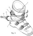
- the pulling element 7 has the following course: Starting from the two ends of the pulling element 7 fastened to the rotary wheel 6a, the adjoining end sections 7', 7" run from the distal end section 3a, on which the actuating device 6 is arranged, essentially in a straight line to the medial end section 3b of the upper shaft part 3. Two deflection devices 9 are fastened to the medial end section 3b, which are designed in such a way that the pulling element 7 can be deflected both in the tensioned state of the pulling element and in the non-tensioned state (cf. Fig. 3 ) is connected to the upper shaft part 3.
- the tension element 7 is also fastened in an open position to both the medial and distal end sections 3a, 3b of the upper shaft part 3, thereby providing a local connection of the tension element 7 on the upper shaft part 3 to the actuating element 6 and to the deflection devices 9. Tangling of the tension element 7, even in an open position of the upper shaft part 3, can thus be reliably prevented.
- a base element 10 is provided which has two through openings 11.
- the tension element 7 in both deflection devices 9 is guided through circumferentially closed through openings 11, so that even in the non-tensioned state of the tension element 7 and in particular in the open position of the upper shaft part 3, the tension element 7 remains connected to the medial end section 3b of the upper shaft part 3.
- the through openings 11 have a larger clear cross-section than the cross-section of the tension element 7, whereby the tension element 7 can be guided through the through openings 11 with relatively low friction losses.
- a deflection element 12 is arranged on the base element 10, each having a circular arc-shaped deflection surface.
- the base element 10 and the deflection element 12 are fastened to the upper shaft part 3 via a common fastening element 13, in particular a screw.
- Both the base element 10 and the deflection element 12 are preferably made of plastic, such as polyamide 6, glass fiber reinforced polyamide 6, polyoxymethylene or the like.
- the deflecting element 12 has a groove 12a in which the tension element 7 is guided.
- a roller particularly made of plastic or metal, can be provided as the deflecting element 12 in order to reduce the friction between the tension element 7 and the deflecting element 12.
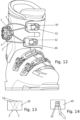
- the two through-openings 11 of a base element 10 each have longitudinal extension axes 11a which are arranged in a V-shape relative to one another such that the tension element 7, in the tensioned state, is guided free of kinks between the deflection device 9 and the actuating element 6. Due to different leg volumes of different users and individual tension of the tension element 7, the exact course of the tension element 7 is not always exactly the same. However, with the V-shaped arrangement of the through-openings 11 relative to one another, the tension element 7 can move independently in a straight line. Arrange them in the direction of pull, which can reduce friction losses and the associated wear.
- two through openings 11 are provided in the base element 10, which are arranged in different planes in plan view (cf. Fig. 14 ) and cross each other (cf. Fig. 13 ).
- the crossing arrangement allows the tension element 7 to align itself even more straightly during tensioning (cf. Fig. 12 ).
- the pulling element 7, after being deflected via the deflection devices 9 at the medial end section 3b, is returned to the distal end section 3a, on which the actuating element 6 is fastened, and is deflected here via a guide element 14, so that - starting from the two ends arranged on the actuating element 6 - a closed course of the pulling element 7 results.
- the guide element 14 can be arranged on the upper shaft part 3 (cf. Fig. 1 and 2 ) from the distal end section 3a of the upper shaft part 3.
- the pulling element 7 remains connected to both end sections 3a, 3b via the actuating element 6 and the deflection devices 9, but at the same time it is ensured that the guidance of the pulling element 7 is so loose that the two end sections 3a, 3b of the upper shaft part 3 can be transferred from an overlapping use position into a non-overlapping open position and thus a comfortable entry and exit into the ski boot 1 is possible.
- the guide element 14 is first positioned at the distal end portion of the upper shaft part. Subsequently, the tension element 7 is tensioned by turning the rotary wheel 6a, and thus the tension element can be moved from a relaxed or non-tensioned state to a tensioned state with the same hand with which the guide element was previously attached to the upper shaft part 3. be transferred.
- a holding element 15a of the holding device 15 which is provided to hold the guide element 14 on the upper shaft part 3 in a use position, can be fastened together with the clamping device 5 on the upper shaft part 3.
- the holding element 15a is arranged partially below the actuating device 6.
- the upper shaft part 3 has a protrusion 16, which is received in a corresponding recess 16' when the holding element 15a is mounted. Due to the angular cross-sectional shape of the protrusion 16 and the recess 16', the holding element 15a is positively secured against rotation.
- the holding device 15 or the holding element 15a and the actuating device 6 are fastened to the upper shaft part 3 via fastening elements 17, in particular screws, whereby only one of the three screws is required for the holding element 15a.
- the holding element 15a is preferably designed in a substantially Z-shaped manner in a side view, ie a curved contact surface 15'' is provided projecting from a fastening surface 15', to which a stop surface 15' in turn adjoins at an angle.
- the guide element 14 has a contact surface 14' curved in accordance with the contact surface 15'', wherein in the position of use the curved contact surface 14' rests on the curved contact surface 15''. As shown in the Figs.
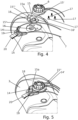
- the guide element 14 remains movable in its functional position arranged on the holding element 15a, ie a sliding movement between the support surface 14' and the contact surface 15'' is possible, so that the guide element 14 can perform a rotating movement about a center of curvature of the curved contact surface 15'' (cf. Figures 9 and 10 ).
- the tension element accommodated in the guide element 14 can automatically align itself during tensioning depending on the tensioning force and volume of the user's leg.
- the stop surface 15′′′ holds the guide element in a positive-locking manner in the direction perpendicular to the plane of extension of the upper shaft part 3, so that Removal of the guide element 14 from the holding element 15a, the guide element 14 must be removed from the holding element 15a against the pulling direction of the pulling element 7, so that the support and contact surfaces 14', 15" are no longer in contact before the guide element 14 can be removed from the holding element 15a.
- the guide element 14 is shown in a position fastened to the upper shaft part 3 via the holding device 15.
- the holding device 15 has a hook-shaped connecting element 18 to secure the guide element 14 to the holding element 15a.
- the connecting element 18 is received in a corresponding receiving groove 19 in the guide element 14, so that the guide element 14 is secured to the holding element 15a in its functional position, but a sliding movement between the support surface 14' and the contact surface 15'' is still possible, so that the guide element 14 can perform a rotating movement in the direction of arrow 14'' around a center of curvature of the curved contact surface 15'' (cf. Figures 9 and 10 ).
- the holding element 15a together with the hook-shaped connecting element 18 is usually made of a plastic material, so that the hook-shaped connecting element 18, after being pivoted out of its rest position, strives to return to the rest position.
- the hook-shaped connecting element 18 is designed as a snap hook.
- a spring element 18a which is made of metal, for example, can be snapped onto the hook-shaped connecting element 18.
- the holding device 15 can comprise a magnetic holding element 15b, which is magnetically connected to a mutually polarized magnet 14b in the guide element 14 in the use position.
- the magnetic holding element 15b is preferably fastened to the upper shaft part 3 via a rivet 15c.
- a particularly user-friendly handling of the guide element 14 is achieved if the guide element 14 has a protruding grip part 20.
- the grip part 20 can, for example, be formed by a tab that is connected to the guide element 14 in an articulated or flexible manner.
Landscapes
- Health & Medical Sciences (AREA)
- General Health & Medical Sciences (AREA)
- Physical Education & Sports Medicine (AREA)
- Footwear And Its Accessory, Manufacturing Method And Apparatuses (AREA)
Applications Claiming Priority (1)
| Application Number | Priority Date | Filing Date | Title |
|---|---|---|---|
| ATA50779/2023A AT527570B1 (de) | 2023-09-25 | 2023-09-25 | Skischuh |
Publications (1)
| Publication Number | Publication Date |
|---|---|
| EP4527232A1 true EP4527232A1 (fr) | 2025-03-26 |
Family
ID=92909615
Family Applications (1)
| Application Number | Title | Priority Date | Filing Date |
|---|---|---|---|
| EP24202407.3A Pending EP4527232A1 (fr) | 2023-09-25 | 2024-09-25 | Chaussure de ski |
Country Status (2)
| Country | Link |
|---|---|
| EP (1) | EP4527232A1 (fr) |
| AT (1) | AT527570B1 (fr) |
Citations (3)
| Publication number | Priority date | Publication date | Assignee | Title |
|---|---|---|---|---|
| WO2020160421A1 (fr) | 2019-02-01 | 2020-08-06 | Boa Technology Inc. | Dispositifs de fermeture à base d'enrouleurs pour serrer une chaussure de ski |
| EP2805639B2 (fr) | 2008-11-21 | 2021-08-18 | Boa Technology, Inc. | Système de laçage à enrouleur |
| EP4212058A1 (fr) * | 2022-01-18 | 2023-07-19 | Salomon S.A.S. | Chaussure de ski et dispositif de serrage associé |
Family Cites Families (2)
| Publication number | Priority date | Publication date | Assignee | Title |
|---|---|---|---|---|
| FR2885494B1 (fr) * | 2005-05-11 | 2007-08-10 | Salomon Sa | Dispositif de fermeture d'une chaussure de sport |
| ITUD20110185A1 (it) * | 2011-11-14 | 2013-05-15 | Calzaturificio Dal Bello S R L | Dispositivo di chiusura per una calzatura sportiva, quale uno scarpone da sci, da snowboard, o simile |
-
2023
- 2023-09-25 AT ATA50779/2023A patent/AT527570B1/de active
-
2024
- 2024-09-25 EP EP24202407.3A patent/EP4527232A1/fr active Pending
Patent Citations (3)
| Publication number | Priority date | Publication date | Assignee | Title |
|---|---|---|---|---|
| EP2805639B2 (fr) | 2008-11-21 | 2021-08-18 | Boa Technology, Inc. | Système de laçage à enrouleur |
| WO2020160421A1 (fr) | 2019-02-01 | 2020-08-06 | Boa Technology Inc. | Dispositifs de fermeture à base d'enrouleurs pour serrer une chaussure de ski |
| EP4212058A1 (fr) * | 2022-01-18 | 2023-07-19 | Salomon S.A.S. | Chaussure de ski et dispositif de serrage associé |
Also Published As
| Publication number | Publication date |
|---|---|
| AT527570B1 (de) | 2025-04-15 |
| AT527570A4 (de) | 2025-04-15 |
Similar Documents
| Publication | Publication Date | Title |
|---|---|---|
| DE60009019T2 (de) | Schuh mit hohem Schaft und Schnürverschluss | |
| DE69701720T3 (de) | Blockiervorrichtung | |
| DE69409579T2 (de) | Klemmvorrichtung für Schnürsenkel | |
| DE19829899B4 (de) | Reibschlüssige Gurteinstellvorrichtung | |
| DE4143410C2 (de) | Sicherheitsbindung | |
| DE60132040T2 (de) | Schuhbindung für Snowboard oder Rollbrett | |
| DE102006034955A1 (de) | Snowboardstiefel | |
| EP0356683A1 (fr) | Dispositif pour la fixation, en particulier de conduits percutanés, comme cathéters, tuyaux d'écoulement, tubes ou analogues sur la peau d'un patient | |
| DE3446877A1 (de) | Bremsbetaetigungseinrichtung fuer ein fahrrad | |
| WO2007016983A1 (fr) | Fermeture rotative pour une chaussure | |
| DE69503978T2 (de) | Schwimmflosse mit Schnalle zur Befestigung des Fersenbandes | |
| EP0259896B1 (fr) | Chaussure de sport, en particulier chaussure de ski | |
| EP1229258B1 (fr) | Mousqueton constitué d'un corps muni d'une ouverture d'accès | |
| EP3143891B1 (fr) | Chaussure de ski | |
| DE1678294B2 (de) | Auslösende Skibindung | |
| AT523145B1 (de) | Schuh, insbesondere Einsatzstiefel, mit einem Schuh-Schnürsystem | |
| AT527570B1 (de) | Skischuh | |
| DE4142391A1 (de) | Skistiefel | |
| AT513382B1 (de) | Klemmvorrichtung für ein Schnürelement | |
| EP0567895A1 (fr) | Chaussure de ski | |
| DE2348905A1 (de) | Ausloesebindung | |
| DE60001912T2 (de) | Vorrichtung zum befestigen von drähten , insbesondere in einer wäschespinne | |
| EP4052604A1 (fr) | Chaussure à lacets | |
| EP0784943A1 (fr) | Chaussure de ski | |
| AT512540A4 (de) | Klemmvorrichtung zum Festklemmen zumindest eines Gurtes |
Legal Events
| Date | Code | Title | Description |
|---|---|---|---|
| PUAI | Public reference made under article 153(3) epc to a published international application that has entered the european phase |
Free format text: ORIGINAL CODE: 0009012 |
|
| STAA | Information on the status of an ep patent application or granted ep patent |
Free format text: STATUS: THE APPLICATION HAS BEEN PUBLISHED |
|
| AK | Designated contracting states |
Kind code of ref document: A1 Designated state(s): AL AT BE BG CH CY CZ DE DK EE ES FI FR GB GR HR HU IE IS IT LI LT LU LV MC ME MK MT NL NO PL PT RO RS SE SI SK SM TR |
|
| STAA | Information on the status of an ep patent application or granted ep patent |
Free format text: STATUS: REQUEST FOR EXAMINATION WAS MADE |
|
| 17P | Request for examination filed |
Effective date: 20250908 |
|
| GRAP | Despatch of communication of intention to grant a patent |
Free format text: ORIGINAL CODE: EPIDOSNIGR1 |
|
| STAA | Information on the status of an ep patent application or granted ep patent |
Free format text: STATUS: GRANT OF PATENT IS INTENDED |
|
| INTG | Intention to grant announced |
Effective date: 20260119 |
|
| GRAS | Grant fee paid |
Free format text: ORIGINAL CODE: EPIDOSNIGR3 |
|
| GRAA | (expected) grant |
Free format text: ORIGINAL CODE: 0009210 |
|
| STAA | Information on the status of an ep patent application or granted ep patent |
Free format text: STATUS: THE PATENT HAS BEEN GRANTED |