EP4527254A2 - Mechanische erweiterungsvorrichtung und aufhängungsmechanismus dafür - Google Patents
Mechanische erweiterungsvorrichtung und aufhängungsmechanismus dafür Download PDFInfo
- Publication number
- EP4527254A2 EP4527254A2 EP25151920.3A EP25151920A EP4527254A2 EP 4527254 A2 EP4527254 A2 EP 4527254A2 EP 25151920 A EP25151920 A EP 25151920A EP 4527254 A2 EP4527254 A2 EP 4527254A2
- Authority
- EP
- European Patent Office
- Prior art keywords
- adjustment rod
- link
- hinged
- leg
- control link
- Prior art date
- Legal status (The legal status is an assumption and is not a legal conclusion. Google has not performed a legal analysis and makes no representation as to the accuracy of the status listed.)
- Pending
Links
Images



Classifications
-
- A—HUMAN NECESSITIES
- A47—FURNITURE; DOMESTIC ARTICLES OR APPLIANCES; COFFEE MILLS; SPICE MILLS; SUCTION CLEANERS IN GENERAL
- A47C—CHAIRS; SOFAS; BEDS
- A47C1/00—Chairs adapted for special purposes
- A47C1/02—Reclining or easy chairs
- A47C1/031—Reclining or easy chairs having coupled concurrently adjustable supporting parts
- A47C1/034—Reclining or easy chairs having coupled concurrently adjustable supporting parts the parts including a leg-rest or foot-rest
- A47C1/035—Reclining or easy chairs having coupled concurrently adjustable supporting parts the parts including a leg-rest or foot-rest in combination with movably-coupled seat and back-rest
- A47C1/0355—Reclining or easy chairs having coupled concurrently adjustable supporting parts the parts including a leg-rest or foot-rest in combination with movably-coupled seat and back-rest actuated by linkages, e.g. lazy-tongs mechanisms
-
- A—HUMAN NECESSITIES
- A47—FURNITURE; DOMESTIC ARTICLES OR APPLIANCES; COFFEE MILLS; SPICE MILLS; SUCTION CLEANERS IN GENERAL
- A47C—CHAIRS; SOFAS; BEDS
- A47C1/00—Chairs adapted for special purposes
- A47C1/02—Reclining or easy chairs
- A47C1/031—Reclining or easy chairs having coupled concurrently adjustable supporting parts
- A47C1/032—Reclining or easy chairs having coupled concurrently adjustable supporting parts the parts being movably-coupled seat and back-rest
- A47C1/03205—Reclining or easy chairs having coupled concurrently adjustable supporting parts the parts being movably-coupled seat and back-rest having adjustable and lockable inclination
- A47C1/03211—Reclining or easy chairs having coupled concurrently adjustable supporting parts the parts being movably-coupled seat and back-rest having adjustable and lockable inclination by electric motors
-
- A—HUMAN NECESSITIES
- A47—FURNITURE; DOMESTIC ARTICLES OR APPLIANCES; COFFEE MILLS; SPICE MILLS; SUCTION CLEANERS IN GENERAL
- A47C—CHAIRS; SOFAS; BEDS
- A47C7/00—Parts, details, or accessories of chairs or stools
- A47C7/36—Supports for the head or the back
- A47C7/40—Supports for the head or the back for the back
- A47C7/46—Supports for the head or the back for the back with special, e.g. adjustable, lumbar region support profile; "Ackerblom" profile chairs
- A47C7/462—Supports for the head or the back for the back with special, e.g. adjustable, lumbar region support profile; "Ackerblom" profile chairs adjustable by mechanical means
Definitions
- the present application relates to a mechanical extension device and a suspension mechanism thereof.
- a mechanical extension device for a floor sofa with armrests in the related art includes a seat unit, a leg unit, a backrest unit, a link structure, and a drive unit, where the drive unit controls the extension of the leg unit and the angle adjustment of the backrest unit.
- the mechanical extension device for the floor sofa with armrests in the related art has the following disadvantages: the mating of the leg unit and the link structure with the seat unit is designed unreasonable, which leads to a relatively high overall height of the mechanical extension device and is not conducive to size control; connecting components are installed on the seat unit to install a wooden frame, but the connecting components are relatively complicated in structure; to reduce a sitting height, the wooden frame is sunk and installed on the inner side of a mounting plate of the seat unit, and a certain interstice exists between the wooden frame and the inner side of the mounting plate, which is prone to dust accumulation and damage and causes poor stability; the structural design of the link structure is unreasonable, resulting in unsmooth operation and affecting user experience, and the link structure has the problem of low structural strength; and the backrest unit has relatively low structural strength and is likely to be easily damaged during use.
- the present application provides a mechanical extension device and a suspension mechanism thereof, which can solve the technical problem in the related art of an unreasonable structural design of a link structure, resulting in unsmooth operation and affecting user experience.
- An embodiment provides a suspension mechanism.
- the suspension mechanism is mounted on a mounting plate of a mechanical extension device and includes a link structure configured to be connected to the mounting plate and including a first link, a second link, and a third link, where a first end of the first link is configured to be hinged to the mounting plate, and a second end of the first link is hinged to the third link; a first end of the second link is configured to be hinged to the mounting plate, and a second end of the second link is hinged to the third link; and the first link, the second link, the third link, and the mounting plate configured to constitute a first four-bar structure; and a control structure connected to the link structure and including a first control link, a second control link, a third control link, and a fourth control link; where a first end of the second control link is hinged to the first control link, and a second end of the second control link is hinged to the third control link; a first end of the fourth control link is hinged to the first control link, and
- An embodiment of the present application provides a mechanical extension device including the preceding suspension mechanism and a seat unit, where the seat unit includes the mounting plate and a mounting plane, and the mounting plate is configured for mounting the suspension mechanism.
- the mechanical extension device includes a seat unit including a mounting plate, where the mounting plate is configured with a mounting plane and has a first rivet point, a second rivet point, a third rivet point, and a fourth rivet point; a link structure configured to be connected to the mounting plate through the first rivet point and the second rivet point on the mounting plate; and a leg unit configured to be connected to the mounting plate through the third rivet point and the fourth rivet point on the mounting plate; where the first rivet point, the second rivet point, and the third rivet point are each below the mounting plane; and a vertical distance between the center of the fourth rivet point and an extension line of the mounting plane of the mounting plate is not greater than 10 mm.
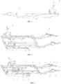
- a mechanical extension device in this embodiment is applicable to a sofa, seat, or wheelchair, and the mechanical extension device includes a seat unit 1, a leg unit 2, a backrest unit 3, a link structure 4, a control structure 5, and a drive unit 6.
- the link structure 4 and the control structure 5 form a suspension mechanism for the mechanical extension device, and the suspension mechanism is mounted on the seat unit 1 of the mechanical extension device.
- the seat unit 1 in this embodiment includes a mounting plate 11.
- An upper plane of the mounting plate 11 is configured for mounting a soft part for sitting.
- the suspension mechanism is mounted on the mounting plate 11.
- the link structure 4 in this embodiment is connected to the mounting plate 11.
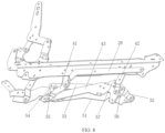
- the link structure 4 includes a first link 41, a second link 42, and a third link 43, where a first end of the first link 41 is hinged to the mounting plate 11, and a second end of the first link 41 is hinged to the third link 43; a first end of the second link 42 is hinged to the mounting plate 11, and a second end of the second link 42 is hinged to the third link 43.
- a hinge point between the first link 41 and the third link 43 and a hinge point between the second link 42 and the third link 43 are located at two ends of the third link 43 separately, and the first link 41, the second link 42, the third link 43, and the mounting plate 11 form a first four-bar structure.
- the first link 41 in this embodiment is substantially L-shaped and thus has better structural strength, and the link structure 4 operates more smoothly.
- the backrest unit 3 in this embodiment is disposed on the mounting plate 11. As shown in FIG. 6 , the backrest unit 3 includes a fixed plate 31, a first backrest adjustment rod 32, a second backrest adjustment rod 33, a third backrest adjustment rod 34, and a fourth backrest adjustment rod 35, where the fixed plate 31 is fixed to the mounting plate 11, a first end of the first backrest adjustment rod 32 is provided with a mounting portion 321 for mounting a backrest, a second end of the first backrest adjustment rod 32 is hinged to the fixed plate 31, and when the first backrest adjustment rod 32 rotates about a hinge point between the first backrest adjustment rod 32 and the fixed plate 31, an angle of the mounting portion 321 may be adjusted.
- the third backrest adjustment rod 34 is hinged to the fixed plate 31 and has a first arm 341 and a second arm 342; a first end of the second backrest adjustment rod 33 is hinged to the first backrest adjustment rod 32, and a second end of the second backrest adjustment rod 33 is hinged to the first arm 341 of the third backrest adjustment rod 34; the second arm 342 of the third backrest adjustment rod 34 is hinged to a first end of the fourth backrest adjustment rod 35; and a second end of the fourth backrest adjustment rod 35 is hinged to a first control link 51, so as to achieve linkage between the control structure 5 and the backrest unit 3.
- the fixed plate 31 in this embodiment is U-shaped.
- the fixed plate 31 includes a body portion 311, a first support arm 312, and a second support arm 313, the first backrest adjustment rod 32 is hinged to the first support arm 312, and the third backrest adjustment rod 34 is hinged to the second support arm 313.
- a stiffener 314 is disposed on the fixed plate 31, and the stiffener 314 is disposed on the body portion 311 and extends to at least the first support arm 312. In an embodiment, the stiffener 314 extends to the second support arm 313.
- the first support arm 312 bears the weight of a reclining user.
- the arrangement of the stiffener 314 can increase the weight that the backrest unit 3 can bear, thereby improving structural strength.
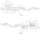
- the control structure 5 in this embodiment is connected to the link structure 4. As shown in FIGS. 5 to 8 , the control structure 5 includes the first control link 51, a second control link 52, a third control link 53, a fourth control link 54, a fifth control link 55, a sixth control link 56, and a seventh control link 57; where a first end of the second control link 52 is hinged to the first control link 51, and a second end of the second control link 52 is hinged to the third control link 53 (referring to a position relationship in FIG.
- a first end of the fourth control link 54 is hinged to the first control link 51, and a second end of the fourth control link 54 is hinged to the third control link 53; and the first control link 51, the second control link 52, the third control link 53, and the fourth control link 54 constitute a second four-bar structure.
- the control structure 5 in this embodiment is connected to the link structure 4, so as to achieve linkage.
- a first end of the fifth control link 55 is hinged to the fourth control link 54 (hinged to an intermediate position of the fourth control link 54), and a second end of the fifth control link 55 is hinged to the third link 43; a first end of the sixth control link 56 is hinged to the second control link 52 (hinged to an intermediate position of the second control link 52), and a second end of the sixth control link 56 is hinged to the third link 43 (referring to a position relationship in FIG. 8 ); and a first end of the seventh control link 57 is hinged to an end of the second control link 52, and a second end of the seventh control link 57 is hinged to the third link 43 (referring to a position relationship in FIGS. 7 and 8 ). In this manner, linkage between the control structure 5 and the link structure 4 is achieved.
- a hinge point between the seventh control link 57 and the second control link 52, a hinge point between the third control link 53 and the second control link 52, a hinge point between the sixth control link 56 and the second control link 52, and a hinge point between the first control link 51 and the second control link 52 are arranged in sequence in a length direction of the second control link 52, and the hinge point between the seventh control link 57 and the second control link 52 and the hinge point between the first control link 51 and the second control link 52 are located at two ends of the second control link 52 in the length direction.
- the leg unit 2 in this embodiment is connected to the mounting plate 11.
- the leg unit 2 includes a first leg adjustment rod 21, a second leg adjustment rod 22, a third leg adjustment rod 23, a fourth leg adjustment rod 24, a fifth leg adjustment rod 25, a sixth leg adjustment rod 26, and a seventh leg adjustment rod 27.
- an end of the first leg adjustment rod 21 is hinged to a first end of the fourth leg adjustment rod 24, and an intermediate position of the first leg adjustment rod 21 is hinged to the second leg adjustment rod 22.
- the third leg adjustment rod 23 is substantially triangular, and the third leg adjustment rod 23 has a first hinge point 231, a second hinge point 232, and a third hinge point 233 at its three corners, where a mounting plane for mounting a soft leg support part is provided along a line between the first hinge point 231 and the third hinge point 233, an end of the second leg adjustment rod 22 is hinged to the first hinge point 231 of the third leg adjustment rod 23, an intermediate position of the fourth leg adjustment rod 24 is hinged to the second hinge point 232 of the third leg adjustment rod 23, and a second end of the fourth leg adjustment rod 24 facing away from the first leg adjustment rod 21 is hinged to the sixth leg adjustment rod 26; a first end of the fifth leg adjustment rod 25 is hinged to the third hinge point 233 of the third leg adjustment rod 23, and a second end of the fifth leg adjustment rod 25 is hinged to the seventh leg adjustment rod 27; the seventh leg adjustment rod 27 is hinged to the mounting plate 11; and the sixth leg adjustment rod 26 is hinged to the mounting plate 11, and an intermediate position of the
- the leg unit 2 in this embodiment further includes a linkage adjustment rod 28.
- the linkage adjustment rod 28 has a first portion 281 and a second portion 282, where an end of the first portion 281 is hinged to the seventh leg adjustment rod 27, and an end of the second portion 282 is hinged to the first link 41.
- the linkage adjustment rod 28 may be driven to rotate, so as to control linkage between the link structure 4 and the leg unit 2.
- the first portion 281 and the second portion 282 are at an angle that is an obtuse angle. In an embodiment, the angle is 100° to 135°. In this manner, the linkage adjustment rod 28 operates more smoothly during linkage.
- the drive unit 6 in this embodiment is connected to the control structure 5 and the leg unit 2 separately.
- the drive unit 6 includes a first bracket 61, a second bracket 62, and a telescopic unit 63, where two ends of the telescopic unit 63 are connected to the first bracket 61 and the second bracket 62 separately to adjust the distance between the first bracket 61 and the second bracket 62.
- the drive unit 6 is connected to the control structure 5.
- the first bracket 61 is connected to the first control link 51.
- the drive unit 6 is connected to the leg unit 2.
- the second bracket 62 is connected to the sixth leg adjustment rod 26.
- the telescopic unit 63 in this embodiment may be an electric adjustment structure with a cylinder structure, a motor structure, or the like as a body so that the telescopic unit 63 can extend and retract. In other embodiments, the telescopic unit may be adjusted by use of a manual structure.
- the telescopic unit 63 rotates the second bracket 62 forward by an angle to push the sixth leg adjustment rod 26 out.
- the mechanical extension device in this embodiment has multiple states to provide different use postures. Specifically, the mechanical extension device has a state for a sitting posture, a state for a leisure posture, and a state for a lying posture.
- the mechanical extension device is in the state for the sitting posture.
- the leg unit 2 is in a collapsed state, and the mounting portion 321 of the first backrest adjustment rod 32 is perpendicular or substantially perpendicular to the mounting plate 11 of the seat unit 1.
- the mechanical extension device is in the state for the leisure posture. Relative to the state for the sitting posture, the leg unit 2 is unfolded to support legs.
- the mechanical extension device is in the state for the lying posture.
- the backrest unit 3 is further reclined (the angle between the mounting portion 321 of the first backrest adjustment rod 32 and the mounting plate 11 of the seat unit 1 increases) so that the user can be in the lying posture.
- a control principle of the mechanical extension device in this embodiment is described below.
- the drive unit 6 In the state for the sitting posture, the drive unit 6 is in an initial state (the distance between the first bracket 61 and the second bracket 62 is the closest).
- the telescopic unit 63 pushes the second bracket 62 and pushes the sixth leg adjustment rod 26 through the second bracket 62, the sixth leg adjustment rod 26 rotates about a hinge point between the sixth leg adjustment rod 26 and the mounting plate 11 to unfold the leg unit 2.
- the first bracket 61 pushes the first control link 51, and the first control link 51 may adjust the angle of the backrest unit 3 (the angle between the mounting portion 321 of the first backrest adjustment rod 32 and the mounting plate 11 of the seat unit 1 increases).
- a mechanical extension device in this embodiment is applicable to a sofa, seat, or wheelchair, especially an electric floor sofa with armrests, and the mechanical extension device includes a seat unit 1, a leg unit 2, a backrest unit 3, a link structure 4, a control structure 5, and a drive unit 6.
- the link structure 4 and the control structure 5 form a suspension mechanism for the mechanical extension device.
- the seat unit 1 in this embodiment includes a mounting plate 11. As shown in FIG. 12 , an upper portion of the mounting plate 11 is configured with a mounting plane 111, and the mounting plate 11 is bent so that the mounting plane 111 is formed directly and used for mounting a wooden frame 7. In an embodiment, the wooden frame 7 may be placed directly on the mounting plane 111 and fixed.
- the angle between the mounting plane and the horizontal plane is 5° to 10°.
- the link structure 4 in this embodiment is connected to the mounting plate 11 through a first rivet point 1111 and a second rivet point 1112 on the mounting plate 11.
- the leg unit 2 in this embodiment is connected to the mounting plate 11 through a third rivet point 1113 and a fourth rivet point 1114 on the mounting plate 11.
- the first rivet point 1111, the second rivet point 1112, and the third rivet point 1113 are each below the mounting plane 111.
- a vertical distance between each of the first rivet point 1111, the second rivet point 1112, the third rivet point 1113, and the fourth rivet point 1114 and the mounting plane 111 of the mounting plate 11 (or an extension line of the mounting plane 111) is not greater than 20 mm. In some embodiments, when the mechanical extension device is in use, the vertical distance between the fourth rivet point 1114 and the extension line of the mounting plane 111 of the mounting plate 11 is not greater than 10 mm.
- the center of the fourth rivet point 1114 is above the mounting plane 111, and a vertical distance between the center of the fourth rivet point 1114 and the extension line of the mounting plane 111 of the mounting plate 11 is not greater than 1 mm.
- the fourth rivet point 1114 when the mechanical extension device is in use, is within 10 mm above the mounting plane 111 or within 10 mm above the extension line in a length direction. In some embodiments, when the mechanical extension device is in use, the fourth rivet point 1114 is within 1 mm above the mounting plane 111 or within 1 mm above the extension line in the length direction. In some other embodiments, when the mechanical extension device is in use, the fourth rivet point 1114 is not lower than the mounting plane 111 in an extension direction of the length direction of the mounting plane 111, that is, a projection of the fourth rivet point 1114 along the length direction of the mounting plane 111 overlaps or is no more than 1 mm higher than a projection of the mounting plane 111 along the length direction of the mounting plane 111.
- the distance in this embodiment refers to a vertical distance from the central point or the center of a rivet point to the mounting plane 111 or the extension line of the mounting plane 111.
- an intersection between the extension line of the mounting plane 111 and an extension line of the outer side of the leg unit 2 is A; when the mechanical extension device is in use, the intersection A has a distance H of 255 mm to 264 mm from the ground.
- the link structure 4 in this embodiment is connected to the mounting plate 11.
- the link structure 4 includes a first link 41, a second link 42, and a third link 43, and the suspension mechanism is connected to and applied to the mechanical extension device through the first link 41 and the second link 42.
- a first end of the first link 41 is hinged to the mounting plate 11.
- the first end of the first link 41 is hinged to the first rivet point 1111 of the mounting plate 11.
- the first end of the first link 41 is directly hinged to the first rivet point 1111 of the mounting plate 11 through a rivet, the first rivet point 1111 is below the mounting plane 111, and the vertical distance between the first rivet point 1111 and the mounting plane 111 is less than 20 mm, 15 mm, or 13mm.
- a second end of the first link 41 is hinged to the third link 43.
- a first end of the second link 42 is hinged to the mounting plate 11.
- the first end of the second link 42 is hinged to the second rivet point 1112 of the mounting plate 11.
- the first end of the second link 42 is directly hinged to the first rivet point 1112 of the mounting plate 11 through a rivet, and the vertical distance between the second rivet point 1112 and the mounting plane 111 is less than 20 mm, 15 mm, or 13mm.
- a second end of the second link 42 is hinged to the third link 43.
- a hinge point between the first link 41 and the third link 43 and a hinge point between the second link 42 and the third link 43 are located at two ends of the third link 43 separately.
- the leg unit 2 in this embodiment further includes a linkage adjustment rod 28, and the linkage adjustment rod 28 is connected to the link structure 4, so as to achieve linkage between the link structure 4 and the leg unit 2.
- the first link 41 in this embodiment is substantially linear.
- first link 41, the second link 42, the third link 43, and the mechanical extension device (the mounting plate 11) connected thereto form a first four-bar structure.
- the backrest unit 3 in this embodiment is disposed on the mounting plate 11.
- the backrest unit 3 includes a fixed plate 31, a first backrest adjustment rod 32, a second backrest adjustment rod 33, a third backrest adjustment rod 34, and a fourth backrest adjustment rod 35, where the fixed plate 31 is fixed to the mounting plate 11, the first backrest adjustment rod 32 has a mounting portion 321 for mounting a backrest, an end of the first backrest adjustment rod 32 is hinged to the fixed plate 31, and when the first backrest adjustment rod 32 rotates about a hinge point between the first backrest adjustment rod 32 and the fixed plate 31, an angle of the mounting portion 321 may be adjusted;
- the third backrest adjustment rod 34 is hinged to the fixed plate 31 and has a first arm 341 and a second arm 342; a first end of the second backrest adjustment rod 33 is hinged to the first backrest adjustment rod 32, and a second end of the second backrest adjustment rod 33 is hinged to the first arm 341 of the third backrest adjustment rod 34; the second arm 342 of the third
- the fixed plate 31 in this embodiment is U-shaped.
- the fixed plate 31 includes a body portion 311, a first support arm 312, and a second support arm 313, the first backrest adjustment rod 32 is hinged to the first support arm 312, and the third backrest adjustment rod 34 is hinged to the second support arm 313.
- a stiffener 314 is disposed on the fixed plate 31, and the stiffener 314 is disposed on the body portion 311 and extends to at least the first support arm 312. In an embodiment, the stiffener 314 extends to the second support arm 313.
- the first support arm 312 bears the weight of a reclining user.
- the arrangement of the stiffener 314 can increase the weight that the backrest unit 3 can bear, thereby improving structural strength.
- the control structure 5 in this embodiment includes a first control link 51, a second control link 52, a third control link 53, a fourth control link 54, a fifth control link 55, a sixth control link 56, and a seventh control link 57; where the fourth backrest adjustment rod 35 is hinged to the first control link 51, so as to achieve the linkage between the control structure 5 and the backrest unit 3; a first end of the second control link 52 is hinged to the first control link 51, and a second end of the second control link 52 is hinged to the third control link 53; a first end of the fourth control link 54 is hinged to the first control link 51, and a second end of the fourth control link 54 is hinged to the third control link 53; and the first control link 51, the second control link 52, the third control link 53, and the fourth control link 54 constitute a second four-bar structure.
- the first control link 51 in this embodiment is provided with at least one set of avoidance holes 511.
- a screw below the first control link 51 is tightened.
- the third link 43 in this embodiment is provided with a notch 431, and the notch 431 corresponds to the avoidance hole 511, so as to give way.
- the control structure 5 in this embodiment is connected to the link structure 4, so as to achieve linkage.
- a first end of the fifth control link 55 is hinged to the fourth control link 54 (hinged to an intermediate position of the fourth control link 54), and a second end of the fifth control link 55 is hinged to the third link 43;
- a first end of the sixth control link 56 is hinged to the second control link 52 (hinged to an intermediate position of the second control link 52), and a second end of the sixth control link 56 is hinged to the third link 43;
- a first end of the seventh control link 57 is hinged to the second control link 52, and a second end of the seventh control link 57 is hinged to the third link 43.
- the leg unit 2 in this embodiment is connected to the mounting plate 11.
- the leg unit 2 includes a first leg adjustment rod 21, a second leg adjustment rod 22, a third leg adjustment rod 23, a fourth leg adjustment rod 24, a fifth leg adjustment rod 25, a sixth leg adjustment rod 26, and a seventh leg adjustment rod 27.
- an end of the first leg adjustment rod 21 is hinged to the fourth leg adjustment rod 24, and an intermediate position of the first leg adjustment rod 21 is hinged to the second leg adjustment rod 22;
- the third leg adjustment rod 23 has a first hinge point 231, a second hinge point 232, and a third hinge point 233, where the first hinge point 231, the second hinge point 232, and the third hinge point 233 are not arranged on the same straight line;
- an end of the second leg adjustment rod 22 is hinged to the first hinge point 231 of the third leg adjustment rod 23, an intermediate position of the fourth leg adjustment rod 24 is hinged to the second hinge point 232 of the third leg adjustment rod 23, and a second end of the fourth leg adjustment rod 24 facing away from the first leg adjustment rod 21 is hinged to the sixth leg adjustment rod 26;
- a first end of the fifth leg adjustment rod 25 is hinged to the third hinge point 233 of the third leg adjustment rod 23, and a second end of the fifth leg adjustment rod 25 is hinged to the seventh leg adjustment rod 27; and the seventh leg adjustment rod 27 is hinge
- an end of the seventh leg adjustment rod 27 is hinged to the third rivet point 1113 of the mounting plate 11. In an embodiment, an end of the seventh leg adjustment rod 27 is directly hinged to the third rivet point 1113 of the mounting plate 11 through a rivet, and the vertical distance between the third rivet point 1113 and the mounting plane 111 is less than 20 mm, 15 mm, or 13mm.
- the sixth leg adjustment rod 26 is hinged to the mounting plate 11. In an embodiment, an end of the sixth leg adjustment rod 26 is hinged to the fourth rivet point 1114 of the mounting plate 11.
- an end of the sixth leg adjustment rod 26 is directly hinged to the fourth rivet point 1114 of the mounting plate 11 through a rivet, and the vertical distance between the fourth rivet point 1114 and the mounting plane 111 or the extension line of the mounting plane 111 is less than 10 mm.
- the vertical distance between the fourth rivet point 1114 and the mounting plane 111 or the extension line of the mounting plane 111 is less than 1 mm.
- An intermediate position of the sixth leg adjustment rod 26 is hinged to an intermediate position of the fifth leg adjustment rod 25.
- a first end of the linkage adjustment rod 28 is hinged to the third link 43, and a second end of the linkage adjustment rod 28 is hinged to the seventh leg adjustment rod 27.
- the linkage adjustment rod 28 rotates, the linkage between the leg unit 2 and the link structure 4 can be controlled.
- the drive unit 6 in this embodiment is connected to the control structure 5 and the leg unit 2 separately.
- the drive unit 6 includes a first bracket 61, a second bracket 62, and a telescopic unit 63, where two ends of the telescopic unit 63 are connected to the first bracket 61 and the second bracket 62 separately to adjust the distance between the first bracket 61 and the second bracket 62.
- the drive unit 6 is connected to the control structure 5.
- the first bracket 61 is connected to the first control link 51.
- the drive unit 6 is connected to the leg unit 2.
- the second bracket 62 is connected to the seventh leg adjustment rod 27.
- the telescopic unit 63 in this embodiment may be an electric adjustment structure with a cylinder structure, a motor structure, or the like as a body so that the telescopic unit 63 can extend and retract.
- the mechanical extension device in this embodiment has multiple states in use to provide different use postures. Specifically, the mechanical extension device has the state for the sitting posture, a state for a leisure posture, and a state for a lying posture.
- the mechanical extension device is in the state for the sitting posture.
- the leg unit 2 is in a collapsed state, and the mounting portion 321 of the first backrest adjustment rod 32 is perpendicular or substantially perpendicular to the mounting plate 11 of the seat unit 1.
- the mechanical extension device is in the state for the leisure posture. Relative to the state for the sitting posture, the leg unit 2 is unfolded to support legs.
- the mechanical extension device is in the state for the lying posture.
- the backrest unit 3 is further reclined (the angle between the mounting portion 321 of the first backrest adjustment rod 32 and the mounting plate 11 of the seat unit 1 increases) so that the user is in the lying posture.
- a control principle of the mechanical extension device in this embodiment is described below.
- the drive unit 6 In the state for the sitting posture, the drive unit 6 is in an initial state (the distance between the first bracket 61 and the second bracket 62 is the closest).
- the telescopic unit 63 pushes the second bracket 62 and pushes the seventh leg adjustment rod 27 through the second bracket 62, the seventh leg adjustment rod 27 rotates about a hinge point between the seventh leg adjustment rod 27 and the mounting plate 11 to unfold the leg unit 2.
- the first bracket 61 pushes the first control link 51, and the first control link 51 may adjust the angle of the backrest unit 3.
- the link structure 4 and the control structure 5 are compact in structure and reasonable in design and thus are adjusted and operated more smoothly, improving use comfort; the backrest unit 3 has enhanced structural strength and is not easy to damage during use; and the vertical distance between the fourth rivet point 1114 and the extension line of the mounting plane 111 is not greater than 10 mm. In an embodiment, the vertical distance between the fourth rivet point 1114 and the extension line of the mounting plane 111 is not greater than 1 mm, thereby reducing the height of the mounting plane and reducing the thickness of the mechanical extension device.
- the mechanical extension device provided in the present application has the following advantages or effects: a simple structure and a reasonable design; a seat frame can be adjusted between multiple states simply by one power unit, relatively reducing a cost; the link structure 4 and the control structure 5 are more compact in structure and more reasonable in design so that the mechanical extension device is adjusted and operated more smoothly, improving the use comfort; the backrest unit 3 has the enhanced structural strength and is not easy to damage during use; the arrangement of the first rivet point 1111, the second rivet point 1112, the third rivet point 1113, and the fourth rivet point 1114 in position can reduce the overall height of the sofa and satisfy the requirement for reducing a sitting height of the sofa.
- the overall thickness of the mechanical extension device can be reduced, that is, with the sitting height unchanged, space at the bottom of the sofa can be increased so that the mechanical extension device can be further applied to a high sofa or a storage function sofa.
- the wooden frame can be directly mounted on the mounting plane, and no interstice exists between the wooden frame and a side edge of the mounting plate, achieving better stability and more convenience of installation.
Landscapes
- Health & Medical Sciences (AREA)
- Dentistry (AREA)
- General Health & Medical Sciences (AREA)
- Engineering & Computer Science (AREA)
- Mechanical Engineering (AREA)
- Chairs For Special Purposes, Such As Reclining Chairs (AREA)
- Vehicle Body Suspensions (AREA)
Applications Claiming Priority (6)
| Application Number | Priority Date | Filing Date | Title |
|---|---|---|---|
| CN202121921433.2U CN215533081U (zh) | 2021-08-17 | 2021-08-17 | 一种机械伸展装置 |
| CN202110940890.4A CN113475898B (zh) | 2021-08-17 | 2021-08-17 | 一种机械伸展装置 |
| CN202110940906.1A CN113475885B (zh) | 2021-08-17 | 2021-08-17 | 一种机械伸展装置及其悬挂机构 |
| CN202121921465.2U CN215533016U (zh) | 2021-08-17 | 2021-08-17 | 一种机械伸展装置及其悬挂机构 |
| EP22857825.8A EP4368068A4 (de) | 2021-08-17 | 2022-08-17 | Mechanische erweiterungsvorrichtung und aufhängungsmechanismus dafür |
| PCT/CN2022/112900 WO2023020514A1 (zh) | 2021-08-17 | 2022-08-17 | 机械伸展装置及其悬挂机构 |
Related Parent Applications (1)
| Application Number | Title | Priority Date | Filing Date |
|---|---|---|---|
| EP22857825.8A Division EP4368068A4 (de) | 2021-08-17 | 2022-08-17 | Mechanische erweiterungsvorrichtung und aufhängungsmechanismus dafür |
Publications (2)
| Publication Number | Publication Date |
|---|---|
| EP4527254A2 true EP4527254A2 (de) | 2025-03-26 |
| EP4527254A3 EP4527254A3 (de) | 2025-07-23 |
Family
ID=85240099
Family Applications (2)
| Application Number | Title | Priority Date | Filing Date |
|---|---|---|---|
| EP22857825.8A Pending EP4368068A4 (de) | 2021-08-17 | 2022-08-17 | Mechanische erweiterungsvorrichtung und aufhängungsmechanismus dafür |
| EP25151920.3A Pending EP4527254A3 (de) | 2021-08-17 | 2022-08-17 | Mechanische erweiterungsvorrichtung und aufhängungsmechanismus dafür |
Family Applications Before (1)
| Application Number | Title | Priority Date | Filing Date |
|---|---|---|---|
| EP22857825.8A Pending EP4368068A4 (de) | 2021-08-17 | 2022-08-17 | Mechanische erweiterungsvorrichtung und aufhängungsmechanismus dafür |
Country Status (3)
| Country | Link |
|---|---|
| US (1) | US12599235B2 (de) |
| EP (2) | EP4368068A4 (de) |
| WO (1) | WO2023020514A1 (de) |
Families Citing this family (8)
| Publication number | Priority date | Publication date | Assignee | Title |
|---|---|---|---|---|
| WO2023020514A1 (zh) * | 2021-08-17 | 2023-02-23 | 德沃康科技集团有限公司 | 机械伸展装置及其悬挂机构 |
| US20240315452A1 (en) * | 2023-03-23 | 2024-09-26 | L&P Property Management Company | High-leg recliner seating mechanism |
| US20240315453A1 (en) * | 2023-03-23 | 2024-09-26 | L&P Property Management Company | High-leg recliner seating mechanism |
| US20240336167A1 (en) * | 2023-04-06 | 2024-10-10 | Camaco, LLC | Constant center lounge seat |
| CN220001288U (zh) * | 2023-05-08 | 2023-11-14 | 海宁和力机械科技有限公司 | 座椅骨架及可切换坐卧姿态的座椅 |
| KR20250089663A (ko) * | 2023-12-12 | 2025-06-19 | 현대자동차주식회사 | 회전 메커니즘 및 이를 포함하는 시트 |
| US20250288116A1 (en) * | 2024-03-14 | 2025-09-18 | Nine Wood Trading Co., Limited | Adjustable sofa |
| MX2024004286A (es) * | 2024-04-05 | 2024-08-08 | Ind Nortecaucanas S A S | Sillon reclinable con mecanismo de reclinacion y ensamblaje de mecanismo de reclinacion para gradas de recintos. |
Family Cites Families (64)
| Publication number | Priority date | Publication date | Assignee | Title |
|---|---|---|---|---|
| US2567612A (en) * | 1949-06-28 | 1951-09-11 | L S Mcclaren | Porch glider |
| US5772278A (en) * | 1996-09-30 | 1998-06-30 | Hickory Springs Manufacturing Company | Recliner chair having wall-avoiding linkage arrangement |
| CN102811729B (zh) * | 2010-01-13 | 2015-02-11 | 托莱多大学 | 钠/钾三磷酸腺苷酶及src相关的材料和方法 |
| PL2994019T3 (pl) * | 2013-05-10 | 2018-09-28 | L&P Property Man Co | Mechanizm łączący do mebla do siedzenia o wysokich nogach |
| US10420422B2 (en) * | 2016-07-29 | 2019-09-24 | L&P Property Management Company | Recliner chair having improved wall clearance and recline linkage with projected back pivot point |
| US10653243B2 (en) | 2016-07-29 | 2020-05-19 | Leggett & Platt, Inc. | Rocker/glider recline linkage with projected back pivot point |
| CN106263778B (zh) * | 2016-10-19 | 2018-12-18 | 礼恩派(嘉兴)有限公司 | 机械伸展装置及包括该机械伸展装置的座椅单元 |
| CN208957347U (zh) | 2018-01-16 | 2019-06-11 | 锐迈机械科技(吴江)有限公司 | 一种功能沙发机械伸展装置 |
| CN209644428U (zh) * | 2018-09-29 | 2019-11-19 | 嘉兴礼海电气科技有限公司 | 一种用于沙发的翻转头靠装置 |
| US10993539B2 (en) * | 2018-09-29 | 2021-05-04 | Okin Refined Electric Technology Co., Ltd | Head and waist integrated device |
| CN111759121B (zh) * | 2019-04-02 | 2024-11-26 | 顾家家居股份有限公司 | 一种机械伸展支架及沙发 |
| US20230200536A1 (en) * | 2019-09-24 | 2023-06-29 | Beech Enterprises, Llc | Adjustable desk chair |
| CN112741445B (zh) | 2019-10-31 | 2025-05-02 | 顾家家居股份有限公司 | 一种沙发的悬挂机构及其使用方法 |
| CN211795449U (zh) * | 2019-12-16 | 2020-10-30 | 江阴凯研金属制造有限公司 | 沙发机械伸展装置 |
| CN213308542U (zh) * | 2019-12-27 | 2021-06-01 | 顾家家居股份有限公司 | 一种用于活动座椅或功能性沙发的机械伸展装置 |
| CN113040555B (zh) | 2019-12-27 | 2024-10-01 | 顾家家居股份有限公司 | 一种用于活动座椅或功能性沙发的机械伸展装置 |
| CN111297113A (zh) * | 2020-03-31 | 2020-06-19 | 礼恩派(嘉兴)有限公司 | 座椅单元的全连杆机械伸展装置 |
| CN212754927U (zh) * | 2020-06-11 | 2021-03-23 | 礼恩派(嘉兴)有限公司 | 伸缩式沙发椅铁架 |
| CN212521294U (zh) | 2020-06-13 | 2021-02-12 | 德沃康科技集团有限公司 | 一种搁腿板组件及智能沙发机械伸展装置 |
| CN212489259U (zh) * | 2020-08-06 | 2021-02-09 | 锐迈机械科技(吴江)有限公司 | 一种沙发伸缩装置 |
| ES3034410T3 (en) * | 2020-11-19 | 2025-08-18 | Dewertokin Tech Group Co Ltd | Ottoman linkage device, frame body, and seat |
| CN214258669U (zh) * | 2021-01-19 | 2021-09-24 | 德沃康科技集团有限公司 | 一种可调节支架和高脚沙发 |
| CN214258670U (zh) * | 2021-01-22 | 2021-09-24 | 德沃康科技集团有限公司 | 一种沙发伸展装置 |
| EP4302654B1 (de) * | 2021-03-02 | 2026-02-25 | DewertOkin Technology Group Co., Ltd. | Sitzkonsole und sitz |
| US12446693B2 (en) * | 2021-03-11 | 2025-10-21 | Dewertokin Technology Group Co., Ltd. | Elderly chair support and elderly chair |
| CN113142880A (zh) * | 2021-05-12 | 2021-07-23 | 礼恩派(嘉兴)有限公司 | 零靠墙的腿部可伸展的功能沙发机构 |
| CN215226144U (zh) * | 2021-05-18 | 2021-12-21 | 德沃康科技集团有限公司 | 一种座椅架及座椅 |
| WO2022257901A1 (zh) * | 2021-06-07 | 2022-12-15 | 德沃康科技集团有限公司 | 伸展单元、调节结构及座椅框架 |
| WO2023011469A1 (zh) * | 2021-08-03 | 2023-02-09 | 锐迈科技股份有限公司 | 一种搁脚延伸机构及座椅伸缩装置 |
| CN113475898B (zh) * | 2021-08-17 | 2024-12-13 | 德沃康科技集团有限公司 | 一种机械伸展装置 |
| CN215533081U (zh) * | 2021-08-17 | 2022-01-18 | 德沃康科技集团有限公司 | 一种机械伸展装置 |
| CN113475885B (zh) * | 2021-08-17 | 2025-02-07 | 德沃康科技集团有限公司 | 一种机械伸展装置及其悬挂机构 |
| WO2023020514A1 (zh) * | 2021-08-17 | 2023-02-23 | 德沃康科技集团有限公司 | 机械伸展装置及其悬挂机构 |
| CN215533016U (zh) * | 2021-08-17 | 2022-01-18 | 德沃康科技集团有限公司 | 一种机械伸展装置及其悬挂机构 |
| WO2023019925A1 (zh) * | 2021-08-18 | 2023-02-23 | 锐迈机械科技(吴江)有限公司 | 一种座椅腿部斜收装置、座椅支架及座椅单元 |
| CN216020114U (zh) * | 2021-08-26 | 2022-03-15 | 海宁和力机械科技有限公司 | 座椅活动装置及座椅总成 |
| US11478083B1 (en) * | 2021-08-31 | 2022-10-25 | Dewertokin Technology Group Co., Ltd. | Sofa backrest adjusting apparatus with integrated headrest and lumbar cushion |
| US11564496B1 (en) * | 2021-08-31 | 2023-01-31 | Dewertokin Technology Group Co., Ltd. | Interlockingly extending driving mechanism for electric sofa |
| WO2023056686A1 (zh) * | 2021-10-08 | 2023-04-13 | 德沃康科技集团有限公司 | 沙发座椅伸展装置 |
| US20250151906A1 (en) * | 2021-10-30 | 2025-05-15 | Dewertokin Technology Group Co., Ltd. | Seat Frame |
| CA3157037C (en) * | 2021-11-30 | 2025-09-09 | Dewertokin Technology Group Co., Ltd. | SEAT FRAME |
| CN216256324U (zh) * | 2021-12-08 | 2022-04-12 | 德沃康科技集团有限公司 | 一种多状态切换的沙发座椅 |
| CN115054079B (zh) * | 2022-06-29 | 2025-11-25 | 东莞市瑞豪家具制造有限公司 | 一种零重力零靠墙的座椅架 |
| CA3262676A1 (en) * | 2022-07-21 | 2024-01-25 | Ultra-Mek, Inc. | RECLINING CHAIR WITH TILTING ACTION FOR CARDIAC REST POSITION |
| CN115177110A (zh) * | 2022-08-09 | 2022-10-14 | 锐迈科技股份有限公司 | 一种座位单元用调节装置及座位单元 |
| CN120166929A (zh) * | 2022-10-17 | 2025-06-17 | 厄特拉-梅克股份有限公司 | 具有操作连接的动力促动器的倾斜座椅单元 |
| US12453422B2 (en) * | 2023-04-07 | 2025-10-28 | Hiddenlake 822 | Two-motor lift and recline system for powered chairs |
| US12310509B2 (en) * | 2023-04-09 | 2025-05-27 | Motomotion China Corporation | Powered rocking lounger chair |
| US12364336B2 (en) * | 2023-04-12 | 2025-07-22 | Emomo Technology (Zhejiang) Co., Ltd. | Mechanical extension device of rocking seat |
| US20250280955A1 (en) * | 2023-04-13 | 2025-09-11 | Ultra-Mek, Inc. | Reclining seating unit for use in theater with riser arrangement |
| CN120957638A (zh) * | 2023-04-13 | 2025-11-14 | 厄特拉-梅克股份有限公司 | 在电影院中使用的具有升降器结构的倾斜座椅单元 |
| US20240365979A1 (en) * | 2023-05-07 | 2024-11-07 | L&P Property Management Company | Three motor recliner mechanism with independent seat, back and ottoman |
| CN220001288U (zh) * | 2023-05-08 | 2023-11-14 | 海宁和力机械科技有限公司 | 座椅骨架及可切换坐卧姿态的座椅 |
| CN219813618U (zh) * | 2023-05-24 | 2023-10-13 | 海宁和力机械科技有限公司 | 座椅骨架及休闲座椅 |
| DE202023103511U1 (de) * | 2023-06-26 | 2023-07-10 | Ciar S.P.A. | Stuhlmechanik für ein Sitz- und Liegemöbel |
| US20250000260A1 (en) * | 2023-06-30 | 2025-01-02 | Remacro Technology Co., Ltd. | Movable seating device and mechanical extension device thereof |
| US12458147B2 (en) * | 2023-08-01 | 2025-11-04 | Hiddenlake 822 Llc | Actuating mechanism or system for a powered furniture seating piece |
| US12408755B2 (en) * | 2023-08-01 | 2025-09-09 | Hiddenlake 822 Llc | Actuating mechanism or system for a powered furniture seating piece |
| CN220800549U (zh) * | 2023-08-28 | 2024-04-19 | 一么么科技(浙江)有限公司 | 电动机械伸展装置 |
| US20250160520A1 (en) * | 2023-09-28 | 2025-05-22 | Remacro Technology Co., Ltd. | Movable seat with swinging device |
| TW202527857A (zh) * | 2023-09-29 | 2025-07-16 | 美商雅詩立傢俱工業有限責任公司 | 可折疊躺椅機構 |
| JP2025536503A (ja) * | 2023-10-27 | 2025-11-07 | 鋭邁科技股▲ふん▼有限公司 | 移動可能な座席ユニットに用いられる機械的伸展装置及び座席ユニット |
| US20250261757A1 (en) * | 2024-02-16 | 2025-08-21 | L & P Property Management Company | Glider mechanism and chair with independent tilt |
| US20250295236A1 (en) * | 2024-03-21 | 2025-09-25 | Hiddenlake 822, Llc | Theater chair or seat with a flip-up/flip-down seat member, a reclining back member, and an automatic return |
-
2022
- 2022-08-17 WO PCT/CN2022/112900 patent/WO2023020514A1/zh not_active Ceased
- 2022-08-17 EP EP22857825.8A patent/EP4368068A4/de active Pending
- 2022-08-17 EP EP25151920.3A patent/EP4527254A3/de active Pending
- 2022-08-17 US US18/292,400 patent/US12599235B2/en active Active
Also Published As
| Publication number | Publication date |
|---|---|
| US20250082099A1 (en) | 2025-03-13 |
| US12599235B2 (en) | 2026-04-14 |
| EP4527254A3 (de) | 2025-07-23 |
| EP4368068A1 (de) | 2024-05-15 |
| EP4368068A4 (de) | 2025-07-23 |
| WO2023020514A1 (zh) | 2023-02-23 |
Similar Documents
| Publication | Publication Date | Title |
|---|---|---|
| EP4527254A2 (de) | Mechanische erweiterungsvorrichtung und aufhängungsmechanismus dafür | |
| US20250000260A1 (en) | Movable seating device and mechanical extension device thereof | |
| CN111955975B (zh) | 具有电动座椅驱动器的零墙壁间隙联动机构 | |
| EP4353128B1 (de) | Erweiterungseinheit, einstellungsstruktur und sitzrahmen | |
| US9808385B2 (en) | Lift-recliner chair | |
| CN1893857B (zh) | 可调节的活动靠背座椅 | |
| US20160206099A1 (en) | Lift-recliner chair | |
| EP4302654B1 (de) | Sitzkonsole und sitz | |
| EP4282306A1 (de) | Vorrichtung zur erweiterung eines sofas | |
| US9314104B2 (en) | Sleep system mechanism | |
| CN114304965B (zh) | 具有高脚设计的隐藏式脚凳躺椅机构 | |
| US20240315452A1 (en) | High-leg recliner seating mechanism | |
| US20240315453A1 (en) | High-leg recliner seating mechanism | |
| CN215533081U (zh) | 一种机械伸展装置 | |
| CN113475898B (zh) | 一种机械伸展装置 | |
| EP4696195A1 (de) | Ausziehbarer rahmen für möbel und sofa damit | |
| CN220458963U (zh) | 一种座椅支架及座椅单元 | |
| CN113116072B (zh) | 一种用于零靠背间隙的座椅支架及座椅单元 | |
| CN215502079U (zh) | 座面倾角调节结构以及休闲椅 | |
| CN112089241B (zh) | 一种采用双电机驱动的座椅框架及座椅 | |
| CN216797094U (zh) | 一种用于低座高沙发的支撑装置及沙发 | |
| CN115227060A (zh) | 一种坐具 | |
| CN108402744B (zh) | 一种多点限位的机械伸展装置 | |
| CN223516014U (zh) | 悬挂机构、功能铁架和可活动沙发 | |
| CN117137285B (zh) | 一种电动沙发铁架组件 |
Legal Events
| Date | Code | Title | Description |
|---|---|---|---|
| PUAI | Public reference made under article 153(3) epc to a published international application that has entered the european phase |
Free format text: ORIGINAL CODE: 0009012 |
|
| STAA | Information on the status of an ep patent application or granted ep patent |
Free format text: STATUS: REQUEST FOR EXAMINATION WAS MADE |
|
| 17P | Request for examination filed |
Effective date: 20250115 |
|
| AC | Divisional application: reference to earlier application |
Ref document number: 4368068 Country of ref document: EP Kind code of ref document: P |
|
| AK | Designated contracting states |
Kind code of ref document: A2 Designated state(s): AL AT BE BG CH CY CZ DE DK EE ES FI FR GB GR HR HU IE IS IT LI LT LU LV MC MK MT NL NO PL PT RO RS SE SI SK SM TR |
|
| PUAL | Search report despatched |
Free format text: ORIGINAL CODE: 0009013 |
|
| AK | Designated contracting states |
Kind code of ref document: A3 Designated state(s): AL AT BE BG CH CY CZ DE DK EE ES FI FR GB GR HR HU IE IS IT LI LT LU LV MC MK MT NL NO PL PT RO RS SE SI SK SM TR |
|
| RIC1 | Information provided on ipc code assigned before grant |
Ipc: A47C 7/00 20060101AFI20250618BHEP Ipc: A47C 1/0355 20130101ALI20250618BHEP Ipc: A47C 1/032 20060101ALI20250618BHEP |