EP4527256A2 - Distributeur pour ustensiles jetables - Google Patents
Distributeur pour ustensiles jetables Download PDFInfo
- Publication number
- EP4527256A2 EP4527256A2 EP25157044.6A EP25157044A EP4527256A2 EP 4527256 A2 EP4527256 A2 EP 4527256A2 EP 25157044 A EP25157044 A EP 25157044A EP 4527256 A2 EP4527256 A2 EP 4527256A2
- Authority
- EP
- European Patent Office
- Prior art keywords
- utensil
- housing
- dispenser
- utensils
- moveable member
- Prior art date
- Legal status (The legal status is an assumption and is not a legal conclusion. Google has not performed a legal analysis and makes no representation as to the accuracy of the status listed.)
- Pending
Links
Images







Classifications
-
- A—HUMAN NECESSITIES
- A47—FURNITURE; DOMESTIC ARTICLES OR APPLIANCES; COFFEE MILLS; SPICE MILLS; SUCTION CLEANERS IN GENERAL
- A47F—SPECIAL FURNITURE, FITTINGS, OR ACCESSORIES FOR SHOPS, STOREHOUSES, BARS, RESTAURANTS OR THE LIKE; PAYING COUNTERS
- A47F1/00—Racks for dispensing merchandise; Containers for dispensing merchandise
- A47F1/04—Racks or containers with arrangements for dispensing articles, e.g. by means of gravity or springs
- A47F1/08—Racks or containers with arrangements for dispensing articles, e.g. by means of gravity or springs dispensing from bottom
- A47F1/10—Racks or containers with arrangements for dispensing articles, e.g. by means of gravity or springs dispensing from bottom having mechanical dispensing means, e.g. with buttons or handles
-
- A—HUMAN NECESSITIES
- A47—FURNITURE; DOMESTIC ARTICLES OR APPLIANCES; COFFEE MILLS; SPICE MILLS; SUCTION CLEANERS IN GENERAL
- A47F—SPECIAL FURNITURE, FITTINGS, OR ACCESSORIES FOR SHOPS, STOREHOUSES, BARS, RESTAURANTS OR THE LIKE; PAYING COUNTERS
- A47F1/00—Racks for dispensing merchandise; Containers for dispensing merchandise
- A47F1/04—Racks or containers with arrangements for dispensing articles, e.g. by means of gravity or springs
- A47F1/08—Racks or containers with arrangements for dispensing articles, e.g. by means of gravity or springs dispensing from bottom
- A47F1/10—Racks or containers with arrangements for dispensing articles, e.g. by means of gravity or springs dispensing from bottom having mechanical dispensing means, e.g. with buttons or handles
- A47F2001/103—Racks or containers with arrangements for dispensing articles, e.g. by means of gravity or springs dispensing from bottom having mechanical dispensing means, e.g. with buttons or handles for cutlery
-
- A—HUMAN NECESSITIES
- A47—FURNITURE; DOMESTIC ARTICLES OR APPLIANCES; COFFEE MILLS; SPICE MILLS; SUCTION CLEANERS IN GENERAL
- A47G—HOUSEHOLD OR TABLE EQUIPMENT
- A47G21/00—Table-ware
- A47G21/02—Forks; Forks with ejectors; Combined forks and spoons; Salad servers
-
- A—HUMAN NECESSITIES
- A47—FURNITURE; DOMESTIC ARTICLES OR APPLIANCES; COFFEE MILLS; SPICE MILLS; SUCTION CLEANERS IN GENERAL
- A47G—HOUSEHOLD OR TABLE EQUIPMENT
- A47G21/00—Table-ware
- A47G21/04—Spoons; Pastry servers
Definitions
- the angle or slant of the ramp 650 works with a swing trajectory of the actuator 660 to pinch or trap pieces of utensil therebetween thereby impeding the movement of utensils against the slope of the ramp 650 ( i.e. up the ramp 650).
- the positioning mechanism 655 provides a fulcrum or single point of contact that can be used to align or re-align a released utensil on the ramp 650.
- the positioning mechanism 655 can provide a point of contact to stabilize or re-direct a utensil as it lands on the gravity ramp 650.
- the positioning mechanism 655 can help a utensil land in a desired orientation after being released from the stack, e . g . lay flat opposed to lay on its side.
- the inner wall 312 of the chassis housing 310 above the ramp 650 can be vertically sloped or canted. Still referring to Figures 7 to 13 , one or both sides of the housing inner walls 312 above the ramp 650 can be sloped.
- the canted portion 312 can angle anywhere from 3 to 40 degrees from vertical.
- the canted portion 312 can slope upward from the ramp 650 at an angle from a low of about 3, 5, or 10 degrees to a high of about 15, 25, or 40 degrees. This sloped surface 312 helps prevent the released utensil from standing on its side by adding a moment to encourage the utensil to rotate and lay flat.
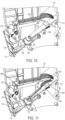
- Figure 16 depicts another enlarged cut away side view of the lower portion of the dispense chassis as the dispensing utensil 22 drives the actuator 660 toward its dispense position, according to one or more embodiments.
- Figure 17 is another view of Figure 16 but with the utensils removed to better illustrate the moving parts of the dispense chassis.
- movement of the actuator 660 causes movement of the drive mechanism 670, which causes the moveable member 680 to retract, allowing the engaging portion 685 of the extension 682 to move under or about the contoured projections 525 of the then next utensil 20.
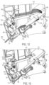
- Figure 18 depicts an enlarged cut away side view of the lower portion of the chassis housing 310 as the dispensing utensil 22 exits the dispense chassis, triggering the release of the then next utensil 20 (i.e. lowermost utensil) from the stack, according to one or more embodiments.
- Figure 19 is another view of Figure 18 but with the utensils removed to better illustrate the moving parts of the dispense chassis. In this depiction, the utensil 22 is about freed from the dispense chassis 150, and the engaging portion 685 of the extension 682 of the moveable member 680 is clearing the front pedestal 610, triggering the release of the then next utensil 20 (i.e. lowermost utensil) from the stack.
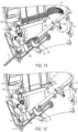
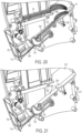
- Figure 20 depicts an enlarged cut away side view of the lower portion of the dispense chassis as the then next utensil 20 releases from the stack. At this point of the cycle, the next utensil lands on the gravity ramp 650 and becomes the released utensil 21 lying on the ramp 650.
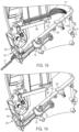
- Figure 21 is another view of Figure 20 but with the utensils removed to better illustrate the moving parts of the dispense chassis. The released utensil 21 can then move down the ramp 650 until caught in the opening 665 of the actuator 660.
- the handle end 50 of the released utensil 21 will extend through the access port 152 and be available for a next user to take, and a new next utensil 20 resides as the lowermost utensil in the stack.
- the process can then start over until all the utensils have been removed from the chamber 320 or interrupted to refill the dispense chassis 150.
- the actuator 660 can include one or more arms or extensions 663 facing the access port 152.
- the arms or extensions 663 can be located proximate the opening 665 and extend from the actuator body toward the access port 152.
- the arms 663 are sized and shaped to exert a force on the one or more wings or detents 525 of the utensil passing through the opening 665.
- the arms or extensions 663 define a height or clearance zone between the upper surface of the ramp 650 and a lowest point on the actuator 660. This clearance zone is greatest when the actuator 660 moves toward the access port 152 toward its open or dispense position and is least when the actuator 660 moves away from the access port 152 toward its closed or resting position.
- the arms 663 can exert a downward force on the detents 525 to pinch or otherwise trap the utensil against the ramp 650 within the clearance zone, preventing the utensil from moving back into the dispense chassis 150.
- the actuator 660 can include two arms 663 that are generally parallel to one another.
- generally parallel it is meant that the arms 663 are mostly parallel to one another, accounting for any insignificant differences off of true parallel.
- the indicator 2030 can display different quantities of utensils within the stack 2205, the quantities being visible through the gauge window 172.
- the indicator 2030 can have different quantities printed on different parts of the indicator 2030.
- the different quantities can be visible through the gauge window 172 one at a time or multiple quantities can be displayed to show that the level is between the quantities displayed.
- the indicator 2030 could have "Full” and/or a green color printed on the indicator 2030 that is visible through the gauge window 172 when the dispense chassis 150 has more than a certain amount of utensils in the utensil stack 2205, more than 50% full, more than 60% full, more than 70 % full more than 80% full, or more than 90% full; "Half-Full” and/or a yellow color printed on the indicator portion that is visible through the gauge window 68 when the dispense chassis 150 has between certain amounts of utensils 20 in the utensil stack 2205, between 10% full and 90% full, between 20% full and 80% full, between 30% full and 70% full, between 40% full and 60% full; and/or "Empty” and/or a red color printed on the indicator 2030 that is visible through the gauge window 172 when the dispense chassis 150 has less than a certain amount of utensils, such as less than 5, less than 4, less than 3, less than 2, or none in the stack 2205.
- the colors can be used to indicate how many full stacks of utensils (the number of utensils in a full stack of utensil refills can vary) can be added to the dispense chassis 150. For example, where a full stack of utensil refills is thirty, green may indicate that less than one full stack of utensil refills will fit within the dispense chassis 150. Yellow can indicate that more than one full stack of utensil refills can be added to the dispense chassis 150, and red can indicate that two full stacks of utensil refills can be added to the dispense chassis 150.
- the first gauge arm 2010 can include any number of extensions or prongs 2040 that are configured to contact a side of the stack 2205.
- the first gauge arm 2020 can include 1 prong, 2 prongs, 3 prongs, 4 prongs, or 5 prongs disposed along its length.
- the first gauge arm 2010 has two prongs as shown in Figures 22-24 .
- the prongs 2040 can be disposed on any suitable position along the length of the first gauge arm 2010. If more than two prongs 2040 are used, the spacing between prongs 2040 can be the same or can vary.
- each prong 2040 can be moveably attached to the first gauge arm 2010 using a clamp or pinch like fastener, so that a prong 2040 can be moved or adjusted along the length of the first gauge arm 2010 based on patterns of use.
- the gauge window 172 can have any suitable height, such as about 2 mm, 3 mm, 5 mm or more, and can display colors, numbers, percentages, or any other indicator to indicate the number of utensils or stack height within the dispense chassis 150.
- the first gauge arm 2010 can swing with gravity and with or without a spring assistance. The weight and/or the center of gravity of the first gauge arm 2010 can be adjusted to change how the utensil stack gauge 2000 operates. The position and/or the number of the prongs 2040 can be adjusted to provide more precise level indicators. Additionally, in an embodiment not shown, the first gauge arm 2010 can be located inside the housing wall 310A such that any one or more of the prongs 2040 can directly contact the utensil stack 2205 without passing through an opening 2045.
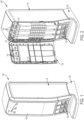
- Figure 25 depicts a perspective view of the illustrative utensil dispenser 100 showing a first dispense chassis 150A in a loading position, and a second and third dispense chassis 150B, 150C in a dispensing position, according to one or more embodiments.
- utensils can be loaded into the first dispense chassis 150A through the loading opening 315.
- the other dispense chassis 150B, 150C when time comes to re-load with utensils.
- Utensils in any dispense chassis that is in the dispensing position 330 can be dispensed while any one of the other dispense chassis is in a loading position.
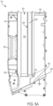
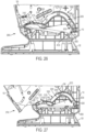
- Figure 26 depicts an illustrative cut away side views of the lower portion of the illustrative dispense chassis 150 to better illustrate the dispense chassis in a dispensing position 2600
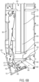
- Figure 27 depicts an illustrative cut away side views of the lower portion of the illustrative dispense chassis 150 to better illustrate the dispense chassis in a loading position 2700.
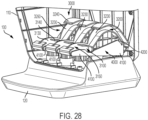
- the utensil dispenser 100 can include a dispense chassis support or glide mechanism 3000 which can be connected to the base 120 of the dispenser housing 110 for supporting at least one utensil dispense chassis 150.
- the glide mechanism 3000 can include one or more slots or channels (two are shown 3100, 3200) for guiding each dispense chassis 150.
- Each slot 3100, 3200 can resemble a guide rail or opening and can be configured to retain a prong or pin appended to a lower portion of each dispense chassis 150.
- Each slot 3100, 3200 can be curvilinear to allow a dispense chassis to pivot or tilt outward, away from the back of the dispenser housing 110. The slope and degree of curvature can be determined based on the size and weight of the dispense chassis 150.
- the spacing between the slots 3100, 3200 can be determined based on the height of the dispense chassis 150 and the needed clearance from the dispenser housing 110.
- each dispense chassis 150 can include a first pin 182 and a second pin 184 that are connected to or integral a lower portion 184 of the dispense chassis 150.
- the first pin 182 and/or second pin 186 are configured to fit and move within the first and second slots 3100 and 3200 of the glide mechanism 3000.
- the first pin 182 and/or second pin 186 can be any rounded cylindrical or tubular shaped structures.
- the first pin 182 and/or second pin 186 can be fixed or stationary.
- the first pin 182 and/or second pin 186 can also be rollers that can roll within their respective slots 3100, 3200.
- the first slot 3100 can include an arcuate shape and can guide the first pin 182 in a forward and upward motion as the dispense chassis 150 is moved from the dispensing position 2600 to the loading position 2700.
- the second slot 3200 can also have an arcuate shape and can guide the second pin 186 in an arcuate and forward motion.
- Each slot 3100, 3200 can include one or more sidewalls 3130, 3230 to provide a rail like containment ( Figure 28 ).
- Each slot 3100, 3200 can also include a covering or upper wall 3140, 3240 to further contain the pins 184, 186 of the dispense chassis 150.
- Each slot 3100, 3200 can further include an upper opening to allow the dispense chassis 150 to be removed from the dispenser housing 110.
- the first slot 3100 can have a first slot opening 3150 through which the first pin 182 can escape the first slot 3100 when removing the dispense chassis 150 from the glide mechanism 3000.
- the second slot 3200 can include a second slot opening 3250 through which the second pin 186 can escape the second slot 3200 when removing the dispense chassis 150 from the glide mechanism 3000.
- the pins 182 and 186 and/or the slots openings 3150, 3250 can be spaced such that only one of the pins 182 and 186 can be removed through its respective slot openings 3150, 3250 at a time.
- the pins 182 and 186 and/or the slots openings 3150, 3250 can also be spaced such that the second slot opening 3250 can be positioned such that the second pin 186 cannot be removed from the second slot 3200 unless the first pin 182 is first removed from its slot 3100. Either or both of these configurations help prevent the dispense chassis 150 from inadvertently falling out of the dispenser housing 110 when moving between the dispensing position 2600 and the loading position 2700.
- the first slot 3100 can include a first end and a second end and a crown 3170 therebetween which is relatively higher than the ends.
- the first pin 182 can be located at the first end of the first slot 3100 when the dispense chassis 150 is in the dispensing position 2600 ( Figure 26 ) and can be located at the second end of the first slot 3100 when the dispense chassis 150 is in the loading position 2700 ( Figure 27 ).
- the crown 3170 can bias the first pin 182 toward the first end or the second end depending on which side of the crown 3170 the first pin 182 is located.
- the second slot 3200 also includes a first end and a second end with a crown 3270 therebetween.
- the second pin 186 of the dispense chassis 150 can be located at the first end of the second slot 3200 when the dispense chassis 150 is in the dispensing position 2600 ( Figure 2600) and can be located at the second end when the dispense chassis 150 is in the loading position 2700 ( Figure 27 ).
- the crown 3270 can bias the second pin 186 toward the first end of the slot 3200 when the second pin 186 is on a first side of the crown 3270 and can bias the second pin 186 toward the second end of the slot 3200 when the second pin 186 is on a second side of the crown 3270.
- the ends of each slot 3100, 3200 provide a stop for the dispense chassis 150 and prevent further movement from the dispensing position 174 and the loading position 172.
- the utensil dispenser 100 can further include a chassis interlock assembly 4000 to help prevent the utensil dispenser 100 from tipping forward due to having too much weight in front of the base 120.
- Each glide mechanism 3000 can be configured with the chassis interlock assembly 4000.
- the chassis interlock 4000 can include at least one body or arm 4100 having a contoured lower surface that is configured to rock on top of the base 120.
- the chassis interlock 4000 can also be mechanically joined to one or more of the glide mechanisms 3000 to rock together as a single unit.
- Each arm 4100 is configured with an upwardly extending post or lock 4200 that is configured to enter into the second slot 3200 of the glide mechanism 3000, preventing the second pin 186 of every chassis 150 in the dispenser at the time from moving past.
- the chassis interlock 4000 tilts forward with the dispense chassis 150, lifting the post 4200 into the back slot 3200, which locks the other dispense chassis 150 in the dispensing position 2600. This is a convenience and a safety feature to keep the utensil dispenser 100 from tipping forward due to having too much weight in front of the base 120.
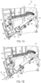
- the dispense chassis interlock assembly 4000 can be in an unlocked position ( Figure 26 ), and any one of the dispense chassis 150 can be moved to the loading position 2700 ( Figure 27 ).
- a first portion of the interlock arm 4100 can be relatively upward (left side in Figures 26-28 ) and the second portion of the interlock arm 4100 can be relatively lower (right side of arm 4100 in Figures 26-28 ).
- the interlock arm 4100 does not interfere with the movement of any of the dispense chassis 150.
- Embodiments of the present disclosure further relate to any one or more of the following paragraphs 1 to 55:
Landscapes
- Table Equipment (AREA)
- Stackable Containers (AREA)
- Details Of Rigid Or Semi-Rigid Containers (AREA)
- Devices For Dispensing Beverages (AREA)
Applications Claiming Priority (3)
| Application Number | Priority Date | Filing Date | Title |
|---|---|---|---|
| US201862734449P | 2018-09-21 | 2018-09-21 | |
| EP19753584.2A EP3852582B1 (fr) | 2018-09-21 | 2019-08-06 | Distributeur pour ustensiles jetables |
| PCT/US2019/045218 WO2020060683A1 (fr) | 2018-09-21 | 2019-08-06 | Distributeur pour ustensiles jetables |
Related Parent Applications (1)
| Application Number | Title | Priority Date | Filing Date |
|---|---|---|---|
| EP19753584.2A Division EP3852582B1 (fr) | 2018-09-21 | 2019-08-06 | Distributeur pour ustensiles jetables |
Publications (2)
| Publication Number | Publication Date |
|---|---|
| EP4527256A2 true EP4527256A2 (fr) | 2025-03-26 |
| EP4527256A3 EP4527256A3 (fr) | 2025-06-04 |
Family
ID=67660020
Family Applications (2)
| Application Number | Title | Priority Date | Filing Date |
|---|---|---|---|
| EP25157044.6A Pending EP4527256A3 (fr) | 2018-09-21 | 2019-08-06 | Distributeur pour ustensiles jetables |
| EP19753584.2A Active EP3852582B1 (fr) | 2018-09-21 | 2019-08-06 | Distributeur pour ustensiles jetables |
Family Applications After (1)
| Application Number | Title | Priority Date | Filing Date |
|---|---|---|---|
| EP19753584.2A Active EP3852582B1 (fr) | 2018-09-21 | 2019-08-06 | Distributeur pour ustensiles jetables |
Country Status (8)
| Country | Link |
|---|---|
| US (1) | US10799036B2 (fr) |
| EP (2) | EP4527256A3 (fr) |
| JP (1) | JP7429225B2 (fr) |
| CN (1) | CN112739240B (fr) |
| AU (1) | AU2019342602A1 (fr) |
| CA (1) | CA3112978A1 (fr) |
| MX (1) | MX2021003202A (fr) |
| WO (1) | WO2020060683A1 (fr) |
Families Citing this family (9)
| Publication number | Priority date | Publication date | Assignee | Title |
|---|---|---|---|---|
| USD910751S1 (en) * | 2017-07-19 | 2021-02-16 | Nordic 24/7 Services Oy | Vending machine |
| US10842293B2 (en) | 2018-01-24 | 2020-11-24 | Gpcp Ip Holdings Llc | Utensil dispensers having improved prime mechanism |
| US10779661B2 (en) | 2018-01-24 | 2020-09-22 | Gpcp Ip Holdings Llc | Utensil dispensers with glide mechanism for loading |
| US10881220B2 (en) | 2018-01-24 | 2021-01-05 | Gpcp Ip Holdings Llc | Utensil dispensers with interlock mechanism |
| US11147393B2 (en) * | 2018-01-24 | 2021-10-19 | Gpcp Ip Holdings Llc | Utensil dispenser with rail system |
| US10881221B2 (en) | 2018-01-24 | 2021-01-05 | Gpcp Ip Holdings Llc | Utensil dispensers with stack gauge |
| CN110811265B (zh) * | 2019-11-01 | 2021-08-17 | 歌乐电磁(深圳)有限公司 | 一种餐具取用器安装装置 |
| USD981183S1 (en) * | 2021-07-05 | 2023-03-21 | Xiamen Yishenger Trading Co., Ltd. | Wall mounted dry food dispenser |
| CN220115696U (zh) * | 2023-05-31 | 2023-12-01 | 歌乐电磁(深圳)有限公司 | 一种餐具下料装置 |
Family Cites Families (147)
| Publication number | Priority date | Publication date | Assignee | Title |
|---|---|---|---|---|
| US592105A (en) | 1897-10-19 | Amos barnes | ||
| US716058A (en) | 1901-10-28 | 1902-12-16 | Thaddeus R Laing | Coin-controlled vending apparatus. |
| US925485A (en) | 1908-08-28 | 1909-06-22 | Francis E Lafler | Match-box. |
| US999837A (en) | 1910-06-17 | 1911-08-08 | Standard Vending Company | Coin-controlled vending-machine. |
| US1259927A (en) | 1912-12-02 | 1918-03-19 | Us Envelope Co | Vending-calinet for collapsible drinking-cups or the like. |
| US1146447A (en) | 1914-05-08 | 1915-07-13 | Harold W C Prommel | Sanitary toothpick-dispenser. |
| US1182793A (en) | 1915-02-27 | 1916-05-09 | Wm Filene S Sons Company | Vending-machine. |
| US1355583A (en) | 1919-10-11 | 1920-10-12 | Solace Comfort Service Corp | Vending-machine |
| US1482071A (en) | 1922-03-06 | 1924-01-29 | Lee F Duff | Dispensing stand |
| US1504098A (en) | 1922-11-27 | 1924-08-05 | Hardy L Cathey | Pencil-dispensing machine |
| US1547151A (en) | 1923-06-15 | 1925-07-21 | John F Watling | Coin-controlled vending machine |
| US1546077A (en) | 1923-12-14 | 1925-07-14 | Cooperative Vending Machine Co | Vending machine |
| US1675510A (en) | 1924-04-08 | 1928-07-03 | John R Nolan | Vending machine |
| FR613105A (fr) | 1925-11-07 | 1926-11-09 | Dispositif distributeur pour cigarettes et autres objets | |
| US1577302A (en) | 1926-01-02 | 1926-03-16 | William N Jenkins | Vending machine |
| US1767634A (en) | 1928-02-06 | 1930-06-24 | Weiss George | Vending machine |
| GB327172A (en) | 1928-12-27 | 1930-03-27 | Dearsley George | Improvements in or relating to packing machinery |
| US2078984A (en) | 1932-01-21 | 1937-05-04 | Ice Cream Dispensing Corp | Package dispensing apparatus |
| US2053828A (en) | 1934-11-09 | 1936-09-08 | Harper Percy Stephen | Coin-freed machine |
| US2110189A (en) | 1936-04-16 | 1938-03-08 | William A Zeidler | Device for dispensing table implements |
| US2149098A (en) | 1936-07-06 | 1939-02-28 | Sani Self Server Corp | Dispensing apparatus for knives and like articles |
| US2149099A (en) | 1937-04-07 | 1939-02-28 | Sani Self Server Corp | Dispensing apparatus |
| US2141684A (en) | 1938-04-05 | 1938-12-27 | Joseph A Diemer | Dispensing device |
| US2188573A (en) | 1938-04-09 | 1940-01-30 | Longo Salvatore | Dispensing |
| US2207528A (en) | 1939-06-28 | 1940-07-09 | Carl A Witt | Sanitary toothpick dispenser |
| US2421782A (en) | 1939-12-28 | 1947-06-10 | William J Gibbs | Dispenser for tableware |
| US2268873A (en) | 1940-02-10 | 1942-01-06 | Oval Wood Dish Corp | Article dispensing device |
| US2268596A (en) | 1940-05-18 | 1942-01-06 | Jerum Henry | Dispensing apparatus |
| US2239196A (en) | 1940-07-01 | 1941-04-22 | Lunvik Rasmus | Vending and display device |
| US2340561A (en) | 1941-08-27 | 1944-02-01 | Renfro Randolph Howard | Spoon dispenser |
| US2427321A (en) | 1945-01-22 | 1947-09-09 | Reliable Sheet Metal Engineeri | Vending machine |
| US2472051A (en) | 1946-11-15 | 1949-05-31 | Gillette Safety Razor Co | Blade-dispensing container |
| US2571668A (en) | 1947-07-12 | 1951-10-16 | Interborough News Company | Coin-controlled vending machine |
| US2646874A (en) | 1947-08-08 | 1953-07-28 | Gillette Co | Blade dispensing magazine |
| US2635025A (en) | 1949-10-28 | 1953-04-14 | Badger Vending Machines Co | Dispensing device |
| US2577344A (en) | 1950-01-10 | 1951-12-04 | Ramona D Masure | Narcotic dispenser |
| US2692691A (en) | 1950-04-15 | 1954-10-26 | Harriss | Nested article dispenser |
| US2868344A (en) | 1955-01-10 | 1959-01-13 | Wendell H Shields | Vending machine |
| US2965262A (en) | 1955-09-06 | 1960-12-20 | Rowe Mfg Co Inc | Gravity feed package merchandising machine |
| US2924357A (en) | 1955-10-18 | 1960-02-09 | Stapling Machines Co | Slat feeder |
| US2954948A (en) | 1956-04-10 | 1960-10-04 | Francis M Johnson | Chaff dispensing system |
| US2877926A (en) | 1956-09-26 | 1959-03-17 | Pfizer & Co C | Article dispensing apparatus |
| US2880907A (en) | 1957-03-06 | 1959-04-07 | Artez F Mainers | Article dispenser |
| US2911127A (en) | 1957-09-05 | 1959-11-03 | Driss | Machine for dispensing spoons or like articles |
| US3028048A (en) | 1959-03-03 | 1962-04-03 | Adolph W Klammer | Combined cutlery storage and dispensing device |
| US3146908A (en) | 1960-03-29 | 1964-09-01 | Seeburg Corp | Vending machine having a plurality of dispensing compartments |
| US3095114A (en) | 1960-09-14 | 1963-06-25 | Rock Ola Mfg Corp | Packet ejector with optional latch |
| US3054528A (en) | 1961-05-29 | 1962-09-18 | Evarts G Loomis | Machines for vending paper and pencils |
| US3114475A (en) | 1961-07-27 | 1963-12-17 | Newsomatic Corp | Vending machine |
| US3163327A (en) | 1962-07-09 | 1964-12-29 | Fisher & Ludlow Ltd | Coin vending machine |
| US3132765A (en) | 1962-07-20 | 1964-05-12 | Florendo Alex | Silverware dispenser |
| US3191802A (en) | 1963-05-22 | 1965-06-29 | Lasting Walter | Automatic nail dispenser |
| US3248156A (en) | 1964-08-03 | 1966-04-26 | Dow Chemical Co | Dispensing package |
| US3300087A (en) | 1965-05-04 | 1967-01-24 | Difco Lab Inc | Article dispensing magazine and a dispenser with removable magazines |
| US3313452A (en) | 1965-10-15 | 1967-04-11 | Katz Jacob | Dispensing device having a pivoted article delivery member |
| US3371821A (en) | 1966-05-25 | 1968-03-05 | Frederick J. Abood Jr. | Dispensing apparatus |
| US3428215A (en) | 1967-08-18 | 1969-02-18 | James E Wells | Dispenser having means to dispense articles alternately from a plurality of sources |
| US3558006A (en) | 1968-11-18 | 1971-01-26 | Benjamin Redmond | Butter pat dispenser |
| US3587922A (en) | 1969-11-05 | 1971-06-28 | Biagio Oriti | Automatic cigarette box |
| US3680736A (en) | 1970-08-05 | 1972-08-01 | Hans Viessmann | Rotary valve dispenser for tablets |
| US3747803A (en) | 1971-12-23 | 1973-07-24 | Procter & Gamble | Dispenser for groups of nested articles |
| US3786959A (en) | 1972-04-05 | 1974-01-22 | K Greb | Paper clip dispenser |
| US4134519A (en) | 1977-10-21 | 1979-01-16 | Burton Barnett | Dispenser for elongate thin flexible articles |
| US4271978A (en) | 1979-05-31 | 1981-06-09 | Champion International Corporation | Stick dispenser |
| US4308974A (en) | 1980-02-29 | 1982-01-05 | Jones Linda M | Tampon dispener |
| US4489854A (en) | 1982-07-26 | 1984-12-25 | Traex Corporation | Dispensing unit for elongated articles |
| US4530445A (en) | 1982-09-28 | 1985-07-23 | Decker David E | Paper clip holder |
| AT390874B (de) * | 1983-02-18 | 1990-07-10 | Jede Automater Ag | Vereinzelungsvorrichtung fuer becher |
| US4850511A (en) | 1987-04-17 | 1989-07-25 | M&M/Mars | Dispensing rack |
| US4896792A (en) | 1987-09-28 | 1990-01-30 | Michel Marchand | Automatic dispensing device for products and central warehouse or store constructed with such devices |
| US5127546A (en) | 1991-08-08 | 1992-07-07 | Chen Ming Ho | Storage bin structure for an automatic vending machine |
| US5263596A (en) | 1991-12-02 | 1993-11-23 | Williams David R | Medication dispenser station sub-assembly |
| US5246138A (en) | 1991-12-23 | 1993-09-21 | Blevins Jr F Mckinley | Sliding drawer slender article dispenser |
| US5191997A (en) | 1992-06-03 | 1993-03-09 | Mechtronics Corporation | Carousel-type gravity feed film dispenser and film cassette therefor |
| US5249705A (en) | 1992-08-12 | 1993-10-05 | Paul A. Wiebel | Coupon dispenser |
| US5509522A (en) | 1992-10-28 | 1996-04-23 | Laidlaw; Ronald W. | Quick release hopper and improved cylindrical dispensing member for individual cigarette vending machine |
| US5586685A (en) | 1994-09-27 | 1996-12-24 | Dorner Mfg. Corp. | Apparatus for dispensing articles |
| DE29508539U1 (de) | 1995-05-23 | 1995-09-28 | Huisman, Ronald, Bussum | Eßgerät für die Aufnahme von stückigen Speisenbestandteilen sowie Kombination aus einem Spender und darin gehaltenen Eßgeräten |
| US5706977A (en) | 1996-03-04 | 1998-01-13 | The Procter & Gamble Company | Modular display device |
| IT1297194B1 (it) * | 1997-01-30 | 1999-08-03 | Magistris Giovanni De | Dispositivo di distribuzione per palette alimentari monouso |
| US5921408A (en) | 1997-11-04 | 1999-07-13 | Fort James Corporation | Cutlery dispenser |
| IT1307781B1 (it) | 1999-07-16 | 2001-11-19 | Stefano Casebasse | Una confezione per una pluralita' di palette per gelato ed altro,manipolabili per rifornire distributori di palette. |
| IT1307782B1 (it) * | 1999-07-16 | 2001-11-19 | Stefano Casebasse | Dispositivo distributore di palette (o cucchiaini) a perdere pergelati ed altro, con congegno per l'estrazione a scorrimento della |
| US6250498B1 (en) | 1999-10-26 | 2001-06-26 | Scott Lovejoy | Spoon dispenser |
| US6336568B1 (en) | 2000-03-15 | 2002-01-08 | Terence Tucker | Cutlery utensil dispenser |
| JP4092452B2 (ja) | 2000-06-05 | 2008-05-28 | 旭精工株式会社 | 箱状体の自動排出装置 |
| USD461663S1 (en) | 2001-01-03 | 2002-08-20 | Terence Tucker | Cutlery dispenser magazine |
| US20020112445A1 (en) | 2001-02-16 | 2002-08-22 | Benny Scaduto | Device for automatically wrapping eating utensils in a napkin |
| USD477941S1 (en) | 2002-04-23 | 2003-08-05 | Terence Tucker | Cutlery dispensing base |
| EP1540605A4 (fr) | 2002-08-08 | 2006-06-07 | Vendo Co | Logique de profondeur a autoapprentissage pour commande de distributeur a plusieurs profondeurs |
| US6837028B1 (en) | 2002-09-03 | 2005-01-04 | Mario L. Miano | Automated flatware and napkin assembling apparatus |
| PL200112B1 (pl) | 2003-09-03 | 2008-12-31 | Antoni Zieliński | Sposób dozowania sztućców jednorazowego użytku i stos sztućców |
| AU2003272162A1 (en) | 2002-09-26 | 2004-04-19 | Benedykt Prusecki | Method of disposable cutlery dispensing, stack of cutlery and dispenser therefor |
| US6832694B2 (en) | 2002-11-07 | 2004-12-21 | Fort James Corporation | Dispenser for cutlery utensils |
| US7076932B2 (en) | 2003-01-21 | 2006-07-18 | Richard Howard Rubin | Apparatus and method for wrapping |
| US7520247B2 (en) | 2003-02-04 | 2009-04-21 | Jerry D. Rutledge | Animal food and treat dispenser |
| US20050082307A1 (en) | 2003-10-21 | 2005-04-21 | Terence Tucker | Cutlery dispenser system |
| AU2004100000A4 (en) | 2004-01-02 | 2004-02-12 | Sands Innovations Pty Ltd | Dispensing stirring implement |
| WO2005072418A2 (fr) | 2004-01-26 | 2005-08-11 | Convenience Enterprises, Inc. | Systeme d'assemblage de jeux de couverts de table |
| US8152004B2 (en) * | 2005-05-05 | 2012-04-10 | Dixie Consumer Products Llc | Dispenser for disposable cutlery and components therefor |
| US8210364B2 (en) * | 2005-05-05 | 2012-07-03 | Dixie Consumer Products Llc | Dispenser for disposable cutlery and components therefor |
| FR2889507A1 (fr) | 2005-08-08 | 2007-02-09 | Yves Almodovar | Dispositif de distribution de touillettes |
| TWM287639U (en) | 2005-09-22 | 2006-02-21 | Fang-Yueh Liao | Dispenser for disposal spoon |
| TWM293720U (en) | 2005-11-30 | 2006-07-11 | Fang-Yueh Liao | Disposable spoon dispenser structure |
| US20070131705A1 (en) | 2005-12-09 | 2007-06-14 | Behravesh Casey B | Object dispenser |
| US7210279B1 (en) | 2005-12-14 | 2007-05-01 | Ahmed Ibrahim A | Device for wrapping a napkin about silverware and associated method |
| CN2865478Y (zh) | 2005-12-24 | 2007-02-07 | 燕山大学 | 自动取汤匙机 |
| US7322172B2 (en) | 2006-05-24 | 2008-01-29 | Wrapmaster, Inc. | Utensil wrapping apparatus and method |
| ITRE20060068A1 (it) | 2006-06-05 | 2007-12-06 | Ducale Macchine Da Caffe | ¿sistema per l¿erogazione automatica di posate¿ |
| US9237815B2 (en) | 2006-11-07 | 2016-01-19 | Dixie Consumer Products Llc | Cutlery dispenser and method of dispensing cutlery |
| JP2010508993A (ja) | 2006-11-07 | 2010-03-25 | ディクシー コンスーマー プロダクツ エルエルシー | カトラリー分配装置およびカトラリー分配方法 |
| US20080128445A1 (en) | 2006-12-05 | 2008-06-05 | Hsi Ping Huang | Dispenser having advertisement counting effect |
| USD607245S1 (en) | 2007-07-11 | 2010-01-05 | Terence Tucker | Slidable cutlery dispenser magazine |
| USD584084S1 (en) | 2007-07-11 | 2009-01-06 | Terence Tucker | Refillable cutlery dispenser magazine |
| US8360273B2 (en) | 2008-10-08 | 2013-01-29 | Dixie Consumer Products Llc | Cutlery utensil dispenser |
| US8701932B2 (en) | 2008-10-08 | 2014-04-22 | Dixie Consumer Products Llc | Cutlery dispenser trays |
| US8070013B2 (en) | 2009-01-06 | 2011-12-06 | Dixie Consumer Products Llc | Cutlery utensil dispensing apparatus and method |
| AU2009251041B2 (en) * | 2009-01-07 | 2014-11-06 | Gebr. Willach Gmbh | A dispensing device for an inclined shelving bottom magazine |
| KR100954569B1 (ko) | 2009-03-30 | 2010-04-22 | (주)에이치티에스 | 스푼 공급 장치 |
| US9295344B2 (en) | 2010-03-19 | 2016-03-29 | Dixie Consumer Products Llc | Cutlery utensil dispenser |
| AU2011246922B2 (en) | 2010-04-26 | 2015-05-14 | Saga Coffee S.P.A. | A stirrer or spoon dispenser for beverage dispensing machines |
| US11083316B1 (en) | 2010-07-07 | 2021-08-10 | Waddington North America, Inc. | Recyclable and dispensable cutlery utensil |
| WO2012078261A1 (fr) | 2010-12-10 | 2012-06-14 | Dixie Consumer Products Llc | Entraînement à vis pour distribuer des couverts de table et procédés associés |
| CA2820650C (fr) | 2010-12-10 | 2019-03-12 | Gpcp Ip Holdings Llc | Mecanisme de distribution pour distributeur d'ustensiles et procedes associes |
| CA2819646C (fr) | 2010-12-14 | 2019-10-01 | Gpcp Ip Holdings Llc | Entrainement par courroie pour distribuer de la coutellerie et procedes associes |
| ITBS20110157A1 (it) | 2011-11-15 | 2013-05-15 | Paolo Bau Castiglioni | Distributore di posate per alimenti e posata utilizzabile con tale distributore |
| US9049948B2 (en) * | 2012-01-27 | 2015-06-09 | Us Foods, Inc. | Utensil dispenser |
| US9226598B1 (en) | 2012-04-24 | 2016-01-05 | William J Knope | Single-serve sanitary module dispensing system |
| EP3030501B1 (fr) | 2013-08-08 | 2018-12-05 | GPCP IP Holdings LLC | Distributeur de couverts à chargement frontal |
| US9560920B2 (en) | 2014-04-11 | 2017-02-07 | Dixie Consumer Products Llc | Forward advancing cutlery dispenser |
| CN103919421B (zh) | 2014-04-21 | 2015-09-09 | 宁波家联塑料科技有限公司 | 一种餐具调羹分发器 |
| CN103919422B (zh) | 2014-04-21 | 2015-07-08 | 宁波家联塑料科技有限公司 | 一种餐具叉子分发器 |
| CN103960919B (zh) | 2014-04-21 | 2017-02-08 | 宁波家联塑料科技有限公司 | 一种一次性餐具自动分发盒 |
| CN203828595U (zh) | 2014-04-21 | 2014-09-17 | 宁波家联塑料科技有限公司 | 一种餐具高速自动分发器 |
| US9700153B2 (en) | 2014-09-30 | 2017-07-11 | Gadsden Coffee Company, Inc. | Automated hygienic cutlery dispenser |
| CN204617801U (zh) | 2015-04-02 | 2015-09-09 | 谢文龙 | 自动餐具盒 |
| WO2017139525A1 (fr) | 2016-02-10 | 2017-08-17 | Jade Group International Llc | Sangle pour chargement de couverts |
| WO2017139527A1 (fr) | 2016-02-10 | 2017-08-17 | Jade Group International Llc | Broche pour chargement de couverts |
| ES2929042T3 (es) | 2016-04-05 | 2022-11-24 | Waddington North America Inc | Sistema y método de apilado de cubertería |
| MX2018015632A (es) | 2016-06-13 | 2019-09-27 | Gpcp Ip Holdings Llc | Dispensador de cubiertos. |
| WO2018006062A1 (fr) | 2016-06-30 | 2018-01-04 | Jade Group International Llc | Distributeur de coutellerie |
| CN110325079B (zh) | 2017-05-22 | 2021-03-23 | R·F·哈伯德 | 器皿分配器系统 |
| US10779661B2 (en) | 2018-01-24 | 2020-09-22 | Gpcp Ip Holdings Llc | Utensil dispensers with glide mechanism for loading |
| US10881220B2 (en) | 2018-01-24 | 2021-01-05 | Gpcp Ip Holdings Llc | Utensil dispensers with interlock mechanism |
| US10842293B2 (en) | 2018-01-24 | 2020-11-24 | Gpcp Ip Holdings Llc | Utensil dispensers having improved prime mechanism |
| US10881221B2 (en) | 2018-01-24 | 2021-01-05 | Gpcp Ip Holdings Llc | Utensil dispensers with stack gauge |
| US11147393B2 (en) | 2018-01-24 | 2021-10-19 | Gpcp Ip Holdings Llc | Utensil dispenser with rail system |
-
2019
- 2019-08-06 EP EP25157044.6A patent/EP4527256A3/fr active Pending
- 2019-08-06 WO PCT/US2019/045218 patent/WO2020060683A1/fr not_active Ceased
- 2019-08-06 US US16/532,839 patent/US10799036B2/en active Active
- 2019-08-06 EP EP19753584.2A patent/EP3852582B1/fr active Active
- 2019-08-06 CN CN201980061236.7A patent/CN112739240B/zh active Active
- 2019-08-06 MX MX2021003202A patent/MX2021003202A/es unknown
- 2019-08-06 AU AU2019342602A patent/AU2019342602A1/en not_active Abandoned
- 2019-08-06 JP JP2021516424A patent/JP7429225B2/ja active Active
- 2019-08-06 CA CA3112978A patent/CA3112978A1/fr active Pending
Also Published As
| Publication number | Publication date |
|---|---|
| JP2022502128A (ja) | 2022-01-11 |
| WO2020060683A1 (fr) | 2020-03-26 |
| AU2019342602A1 (en) | 2021-04-15 |
| US20200093281A1 (en) | 2020-03-26 |
| EP3852582B1 (fr) | 2025-02-12 |
| CN112739240B (zh) | 2024-01-19 |
| CN112739240A (zh) | 2021-04-30 |
| EP4527256A3 (fr) | 2025-06-04 |
| MX2021003202A (es) | 2021-05-27 |
| CA3112978A1 (fr) | 2020-03-26 |
| US10799036B2 (en) | 2020-10-13 |
| EP3852582A1 (fr) | 2021-07-28 |
| JP7429225B2 (ja) | 2024-02-07 |
Similar Documents
| Publication | Publication Date | Title |
|---|---|---|
| US10799036B2 (en) | Dispenser for disposable utensils | |
| US11147393B2 (en) | Utensil dispenser with rail system | |
| US10842293B2 (en) | Utensil dispensers having improved prime mechanism | |
| US10779661B2 (en) | Utensil dispensers with glide mechanism for loading | |
| US10881221B2 (en) | Utensil dispensers with stack gauge | |
| US10881220B2 (en) | Utensil dispensers with interlock mechanism |
Legal Events
| Date | Code | Title | Description |
|---|---|---|---|
| PUAI | Public reference made under article 153(3) epc to a published international application that has entered the european phase |
Free format text: ORIGINAL CODE: 0009012 |
|
| STAA | Information on the status of an ep patent application or granted ep patent |
Free format text: STATUS: THE APPLICATION HAS BEEN PUBLISHED |
|
| AC | Divisional application: reference to earlier application |
Ref document number: 3852582 Country of ref document: EP Kind code of ref document: P |
|
| AK | Designated contracting states |
Kind code of ref document: A2 Designated state(s): AL AT BE BG CH CY CZ DE DK EE ES FI FR GB GR HR HU IE IS IT LI LT LU LV MC MK MT NL NO PL PT RO RS SE SI SK SM TR |
|
| PUAL | Search report despatched |
Free format text: ORIGINAL CODE: 0009013 |
|
| AK | Designated contracting states |
Kind code of ref document: A3 Designated state(s): AL AT BE BG CH CY CZ DE DK EE ES FI FR GB GR HR HU IE IS IT LI LT LU LV MC MK MT NL NO PL PT RO RS SE SI SK SM TR |
|
| RIC1 | Information provided on ipc code assigned before grant |
Ipc: A47F 1/10 20060101AFI20250429BHEP |
|
| STAA | Information on the status of an ep patent application or granted ep patent |
Free format text: STATUS: REQUEST FOR EXAMINATION WAS MADE |
|
| 17P | Request for examination filed |
Effective date: 20251127 |