EP4527512A1 - Machine à laver pour le lavage de récipients vides, apte à être rempli avec un produit versable - Google Patents
Machine à laver pour le lavage de récipients vides, apte à être rempli avec un produit versable Download PDFInfo
- Publication number
- EP4527512A1 EP4527512A1 EP23199104.3A EP23199104A EP4527512A1 EP 4527512 A1 EP4527512 A1 EP 4527512A1 EP 23199104 A EP23199104 A EP 23199104A EP 4527512 A1 EP4527512 A1 EP 4527512A1
- Authority
- EP
- European Patent Office
- Prior art keywords
- tank
- washing machine
- heat exchanger
- cleaning fluid
- fluid
- Prior art date
- Legal status (The legal status is an assumption and is not a legal conclusion. Google has not performed a legal analysis and makes no representation as to the accuracy of the status listed.)
- Pending
Links
Images

Classifications
-
- B—PERFORMING OPERATIONS; TRANSPORTING
- B08—CLEANING
- B08B—CLEANING IN GENERAL; PREVENTION OF FOULING IN GENERAL
- B08B9/00—Cleaning hollow articles by methods or apparatus specially adapted thereto
- B08B9/08—Cleaning containers, e.g. tanks
- B08B9/20—Cleaning containers, e.g. tanks by using apparatus into or on to which containers, e.g. bottles, jars, cans are brought
- B08B9/22—Cleaning containers, e.g. tanks by using apparatus into or on to which containers, e.g. bottles, jars, cans are brought the apparatus cleaning by soaking alone
- B08B9/24—Cleaning containers, e.g. tanks by using apparatus into or on to which containers, e.g. bottles, jars, cans are brought the apparatus cleaning by soaking alone and having conveyors
-
- B—PERFORMING OPERATIONS; TRANSPORTING
- B08—CLEANING
- B08B—CLEANING IN GENERAL; PREVENTION OF FOULING IN GENERAL
- B08B2203/00—Details of cleaning machines or methods involving the use or presence of liquid or steam
- B08B2203/007—Heating the liquid
-
- B—PERFORMING OPERATIONS; TRANSPORTING
- B08—CLEANING
- B08B—CLEANING IN GENERAL; PREVENTION OF FOULING IN GENERAL
- B08B9/00—Cleaning hollow articles by methods or apparatus specially adapted thereto
- B08B9/08—Cleaning containers, e.g. tanks
- B08B9/20—Cleaning containers, e.g. tanks by using apparatus into or on to which containers, e.g. bottles, jars, cans are brought
- B08B9/28—Cleaning containers, e.g. tanks by using apparatus into or on to which containers, e.g. bottles, jars, cans are brought the apparatus cleaning by splash, spray, or jet application, with or without soaking
- B08B9/30—Cleaning containers, e.g. tanks by using apparatus into or on to which containers, e.g. bottles, jars, cans are brought the apparatus cleaning by splash, spray, or jet application, with or without soaking and having conveyors
Definitions
- the present invention relates to a washing machine for washing (and cleaning) empty containers adapted to be filled with a pourable product, preferably a pourable food product.
- Washing machines are known which are configured for washing and cleaning containers (usually used containers which have been emptied from the pourable product they are adapted to contain) upstream of a filling machine and a labelling machine, in which the containers are respectively filled with the pourable product and labelled with respective labels.
- washing machine is known from EP-A-2727660 in the name of the same Applicant.
- a typical washing machine of the above type essentially comprises:
- the chain conveyor comprises a plurality of beams, which are fed at the inlet station by the feeding system with respective rows of containers.
- each beam comprises a plurality of aligned pockets organized in respective rows, each pocket being configured to receive one container to be treated at a time, to convey such container from the inlet station to the outlet station through the washing tunnel and along the washing path, and to deliver the respective washed container at the outlet station.
- each beam is discharged of the respective washed containers at the outlet station and then is conveyed along a return path back to the inlet station, where it receives new empty containers to be washed.
- the treatment zones comprise, in sequence: a prewash zone, a cleaning zone and a rinsing zone.
- the prewash zone and the cleaning zone comprise, each, at least one cleaning bath defined by respective tanks which are filled with washing chemical agents and through which the containers are advanced.
- the rinsing zone comprises several rinsing baths filled with rinsing liquid and/or ejecting devices for directing sprinkles of rinsing liquid toward the containers.
- the at least one cleaning bath of the cleaning zone comprises a tank which is apt to be filled with a detergent cleaning solution or fluid, typically in liquid state.
- the containers need to be treated through the cleaning zone for a relatively long time and at relatively high temperatures in order to be effectively deprived from the most encrusted dirt mounds, especially the ones heavily sedimented at the bottom of the containers themselves.
- the liquid cleaning solution has to be heated and maintained at a predetermined temperature for the entire duration of the washing process.
- the cleaning bath of the cleaning zone further comprises a heater for heating the cleaning solution.
- the heater is a heat exchanger, whereby heating fluid (such as purified water or water vapor) is circulated to exchange heat with the cleaning solution.
- heating fluid such as purified water or water vapor
- the heat exchanger is arranged within the tank and therefore directly immersed in the cleaning solution.
- the heat exchanger has a tube bundle and such tube bundle is immersed in the cleaning solution within the tank and is directly lapped by the cleaning solution. This configuration ensures an optimal heat exchange between the heating fluid and the cleaning solution, since the thermal exchange is quite high.
- the respective tank has to be emptied from the cleaning solution.
- the emptying of the tank can be quite time consuming.
- a large storage container is needed to stock the cleaning solution in the meantime, or the entire cleaning solution has to be thrown away, which results in increased overall costs.
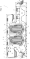
- number 1 indicates as a whole a washing machine configured to wash empty containers 2 adapted to be filled with a pourable product, preferably a pourable food product, such as beer, wine, water, juice, soft drinks, milk or the like.
- a pourable product such as beer, wine, water, juice, soft drinks, milk or the like.
- containers 2 are defined by respective empty bottles (for example, returnable glass bottles) intended to be filled with the pourable product.
- Washing machine 1 comprises:
- the conveyor device comprises a looped chain conveyor 4 (of the type known and only schematically shown) for advancing containers 2 along washing path P inside washing tunnel 3, so as to convey containers 2 from one end of the tunnel 3 to the other end along a general direction D, preferably horizontal with respect to gravity.
- a looped chain conveyor 4 (of the type known and only schematically shown) for advancing containers 2 along washing path P inside washing tunnel 3, so as to convey containers 2 from one end of the tunnel 3 to the other end along a general direction D, preferably horizontal with respect to gravity.
- chain conveyor 4 may be of the type described in WO-A-2020119958 and comprises:
- each beam comprises a row of pockets 6 (laterally shown) aligned orthogonally to path P and configured to receive corresponding containers 2.
- containers 2 carried by a corresponding beam 5 are aligned orthogonally to path P and housed inside the respective pockets 6, individually.
- Washing machine 1 comprises also a feeding system 7 of the known type (only schematically shown in Figure 1 ) for feeding a sequence of empty containers 2 along direction D and at an inlet station I of washing tunnel 3. Expediently, containers 2 are fed by feeding system 7 along direction D arranged in rows orthogonal to path P.
- the most forward containers 2 of each row of containers 2 are transferred by feeding system 7 to the respective pockets 6 of the beam 5 that is travelling at inlet station I.
- Washing machine 1 further comprises an outfeed system 8, which receives rows of cleaned containers 2 from chain conveyor 4 at an outlet station O of washing tunnel 3.
- path P comprises:
- washing machine 1 comprises in sequence along washing branch P1:
- washing machine 1 at the prewash zone C1, cleaning zone C2 and final rinsing zone C3 is well-known, for example from WO-A-2020119958 , and therefore will not be described in detail herein.
- Cleaning zone C2 comprises at least one cleaning bath 10, in particular a plurality of cleaning baths 10, in the embodiment shown two successive cleaning baths 10.
- Cleaning bath 10 includes a tank 11 which is configured for holding a cleaning fluid F, such as a detergent chemical solution made of several chemical agents.
- a cleaning fluid F such as a detergent chemical solution made of several chemical agents.
- cleaning fluid F comprises basic aqueous solutions that include, in particular, sodium hydroxide.
- tank 11 is filled with the cleaning fluid F up to a predetermined level.
- path P and in particular washing branch P1, extends through tank 11, so that the containers 2 advanced by it are advanced through cleaning fluid F and are temporarily immersed therein.
- cleaning fluid F is brought (and maintained) to a predetermined temperature, for instance between 65°C and 80°C.
- washing machine 1 and in particular cleaning bath 10, comprises a heat exchanger 12 configured to heat the cleaning fluid F contained in tank 11 by means of heat exchange between cleaning fluid F and a heating fluid H.
- heating fluid H is water, in particular purified water.
- heating fluid H may be water vapor or another heating medium apt to the above aim.
- heat exchanger 12 comprises an outer casing 13, internally delimiting an exchange chamber 13a, and an inner tubing 14 at least partially enclosed within casing 13 and extending through exchange chamber 13a.
- casing 13 defines an outer mantle of heat exchanger 12.
- tubing 14 includes a tube bundle and casing 13 defines a shell of heat exchanger 12, so that heat exchanger 12 is a shell-and-tube heat exchanger.
- tubing 14 may include a single duct zigzagging within exchange chamber 13a (i.e. a heating "serpentine" tube).
- exchange chamber 13a is configured to be fed with heating fluid H and tubing 14 is configured to be fed with cleaning fluid F from the tank 11, so that a heat exchange is established between the heating fluid H in exchange chamber 13a and the cleaning fluid F within tubing 14.
- the cleaning fluid F contained in tank 11 is circulated within tubing 14 and heating fluid H is circulated within exchange chamber 13a.
- exchange chamber 13a only receives heating fluid H and is fluidly isolated from tank 11.
- first circuit 15 comprises a suction duct 15a arranged fluidly upstream of heat exchanger 12 and configured for conveying cleaning fluid F to be heated from tank 11 to heat exchanger 12, in particular to tubing 14, and a delivery duct 15b arranged fluidly downstream of heat exchanger 12 and configured for conveying heated cleaning fluid F from tubing 14 back into tank 11.
- second circuit 16 includes a suction duct 16a fluidly connecting source 17 to exchange chamber 13a, and a delivery duct 16b for conveying heating fluid H out of exchange chamber 13a.
- heat exchanger 12 includes a first exchange interface 19 defined between tubing 14 and exchange chamber 13a.
- first exchange interface 19 is defined by an outer surface of tubing 14.
- heat exchanger 12 As described above, the operations of maintenance on heat exchanged 12 (and therefore on washing machine 1) are significantly eased and improved, since exchange chamber 13a is fluidly isolated from tank 11 and therefore it is not necessary to empty tank 11 from cleaning fluid F during maintenance operations.
- the configuration of heat exchanger 12 according to the invention highly reduces the risk of clogging, with respect to the known configurations whereby heating fluid H is circulated in the tubing and cleaning fluid F is circulated in the exchange chamber, or with respect to plate-type heat exchangers, which are even more prone to clogging.
- exchange chamber 13a typically has many interstices and fluid-diverting members (not shown) for liquid mixing and shuffling, which can be easily clogged. For this reason, exchange chamber 13a is rather uncleanable.
- tubing 14 are relatively smooth and high in diameter, so they are less prone to clogging.
- a normal-performance filter is sufficient, such as a net-filter with a filtering size smaller than the diameter of the ducts of tubing 14. In this way, overall costs are further reduced.
- heat exchanger 12 is arranged at least partially within tank 11 and extends through tank 11.
- casing 13 of heat exchanger 12 is at least partially surrounded by cleaning fluid F in tank 11 when, in use, tank 11 contains and holds cleaning fluid F.
- casing 13 separates and fluid-tightly seals exchange chamber 13a from tank 11 and from the cleaning fluid F containable therein (i.e. contained in use therein).
- heat exchanger 12 occupies less space in washing machine 1 compared to a fully external heat exchanger arranged outside tank 11.
- washing machine 1 has a leaner layout and an improved architecture, while at the same time benefitting from the already mentioned easy maintenance, as it is not necessary to empty tank 11 to perform maintenance on heat exchanger 12.
- heat exchanger 12 according to the invention can be easily retrofitted in the known washing machines 1: in fact, the immersed heat exchangers mentioned in the introductory part of the present description can be easily replaced by heat exchangers 12, without the need for finding an alternative place for them within washing tunnel 3. This makes the layout leaner.
- casing 13 is made of a thermally conductive material.
- heat exchanger 12 includes a second exchange interface 20 defined between casing 13 and tank 11.
- washing machine 1 is further configured so that the heating fluid H in exchange chamber 13a exchanges heat with the cleaning fluid F in tank 11 directly via second exchange interface 20, i.e. directly through casing 13.
- heat exchanger 12 includes an access portion 21 which protrudes outside of tank 11.
- casing 13 includes such access portion 21.
- access portion 21 comprises an access door 22 for accessing, and preferably directly accessing, exchange chamber 13a.
- washing machine 1 comprises a control unit 23 (of the known type).
- first circuit 15 includes a temperature sensor 24 for detecting a temperature of cleaning fluid F within tank 11.
- control unit 23 is configured for receiving from the temperature sensor 24 a temperature signal correlated with a detected temperature value of cleaning fluid F, and for controlling pumping device 18 as a function of the temperature signal received.
- pumping device 18 can be activated only when necessary for circulating cleaning fluid F within tubing 14, thereby resulting in energy savings.
- washing machine 1 comprises a label extraction unit (only partially shown in Figure 1 ) which is at least partially arranged within tank 11 and which comprises label detaching means (not shown, such as a high-pressure pump) configured to act on the containers 2 for detaching the labels therefrom and a collection compartment 25 for collecting the detached labels.
- label extraction unit only partially shown in Figure 1
- label detaching means such as a high-pressure pump
- suction duct 15a is fluidly connected with tank 11 in a position outside of the collection compartment 25 for withdrawing therefrom cleaning fluid F to be heated.
- cleaning fluid F is fed to heat exchanger 12 and through tubing 14 without altering or hindering the operation of the label extraction unit. Also, removed labels are prevented to accidentally enter tubing 14.
- delivery duct 15b is fluidly connected to tank 11 in a position within the collection compartment 25 for feeding heated cleaning fluid F at the collection compartment 25.
- washing machine 1 according to the present invention will be clear from the foregoing description.
- heat exchanger 12 Since cleaning fluid F is circulated within tubing 14 and heating fluid H is circulated within exchange chamber 13a (i.e. within the mantle of heat exchanger 12), and to its positioning within tank 11, albeit with exchange chamber 13a fluidly isolated from it, maintenance and cleaning operations of heat exchanger 12 are significantly eased and improved.
- washing machine 1 as described herein without, however, departing from the scope of protection as defined in the accompanying claims.
Landscapes
- Engineering & Computer Science (AREA)
- Mechanical Engineering (AREA)
- Cleaning By Liquid Or Steam (AREA)
Priority Applications (1)
| Application Number | Priority Date | Filing Date | Title |
|---|---|---|---|
| EP23199104.3A EP4527512A1 (fr) | 2023-09-22 | 2023-09-22 | Machine à laver pour le lavage de récipients vides, apte à être rempli avec un produit versable |
Applications Claiming Priority (1)
| Application Number | Priority Date | Filing Date | Title |
|---|---|---|---|
| EP23199104.3A EP4527512A1 (fr) | 2023-09-22 | 2023-09-22 | Machine à laver pour le lavage de récipients vides, apte à être rempli avec un produit versable |
Publications (1)
| Publication Number | Publication Date |
|---|---|
| EP4527512A1 true EP4527512A1 (fr) | 2025-03-26 |
Family
ID=88147102
Family Applications (1)
| Application Number | Title | Priority Date | Filing Date |
|---|---|---|---|
| EP23199104.3A Pending EP4527512A1 (fr) | 2023-09-22 | 2023-09-22 | Machine à laver pour le lavage de récipients vides, apte à être rempli avec un produit versable |
Country Status (1)
| Country | Link |
|---|---|
| EP (1) | EP4527512A1 (fr) |
Citations (6)
| Publication number | Priority date | Publication date | Assignee | Title |
|---|---|---|---|---|
| US2617435A (en) * | 1948-09-25 | 1952-11-11 | Michael Yundt Company | Bottle-washing machine |
| US4512811A (en) * | 1982-03-01 | 1985-04-23 | Seitz Enzinger Noll Maschinenbau Aktiengesellschaft | Method and apparatus for cleaning containers |
| DE4212433A1 (de) * | 1992-04-14 | 1993-10-21 | Holstein & Kappert Maschf | Flaschenreinigungsmaschine mit mehreren in Flaschendurchlaufrichtung angeordneten Behandlungszonen |
| DE19502272A1 (de) * | 1995-01-26 | 1996-08-01 | Kronseder Maschf Krones | Flaschenreinigungsmaschine in Einendbauweise |
| EP2727660A1 (fr) | 2012-11-05 | 2014-05-07 | Sidel S.p.A. Con Socio Unico | Unité de traitement de récipients et procédé pour la reconfiguration d'une unité de traitement de récipients |
| WO2020119958A1 (fr) | 2018-12-13 | 2020-06-18 | Sidel End Of Line & Tunnels Solutions Srl | Machine à laver pour laver des récipients vides et son procédé de fonctionnement |
-
2023
- 2023-09-22 EP EP23199104.3A patent/EP4527512A1/fr active Pending
Patent Citations (6)
| Publication number | Priority date | Publication date | Assignee | Title |
|---|---|---|---|---|
| US2617435A (en) * | 1948-09-25 | 1952-11-11 | Michael Yundt Company | Bottle-washing machine |
| US4512811A (en) * | 1982-03-01 | 1985-04-23 | Seitz Enzinger Noll Maschinenbau Aktiengesellschaft | Method and apparatus for cleaning containers |
| DE4212433A1 (de) * | 1992-04-14 | 1993-10-21 | Holstein & Kappert Maschf | Flaschenreinigungsmaschine mit mehreren in Flaschendurchlaufrichtung angeordneten Behandlungszonen |
| DE19502272A1 (de) * | 1995-01-26 | 1996-08-01 | Kronseder Maschf Krones | Flaschenreinigungsmaschine in Einendbauweise |
| EP2727660A1 (fr) | 2012-11-05 | 2014-05-07 | Sidel S.p.A. Con Socio Unico | Unité de traitement de récipients et procédé pour la reconfiguration d'une unité de traitement de récipients |
| WO2020119958A1 (fr) | 2018-12-13 | 2020-06-18 | Sidel End Of Line & Tunnels Solutions Srl | Machine à laver pour laver des récipients vides et son procédé de fonctionnement |
Similar Documents
| Publication | Publication Date | Title |
|---|---|---|
| US4154624A (en) | Apparatus and method for cleaning containers | |
| KR20130028945A (ko) | 용기의 살균, 세정 방법 | |
| US20100212699A1 (en) | Apparatus for cleaning containers | |
| US3162204A (en) | Apparatus for removing labels from bottle washers | |
| EP4527512A1 (fr) | Machine à laver pour le lavage de récipients vides, apte à être rempli avec un produit versable | |
| CN109414736B (zh) | 瓶清洁装置和使用瓶清洁装置清洁瓶的方法 | |
| US12194513B2 (en) | Cleaning and sterilizing method for aseptic filling machine and aseptic filling machine | |
| BRPI1100340A2 (pt) | sistemas de limpeza para recipientes, e, mÉtodo de limpeza de recipientes | |
| EP3666404B1 (fr) | Machine à laver pour laver des récipients vides et son procédé de fonctionnement | |
| ES2987898T3 (es) | Dispositivo para limpiar botellas | |
| US2418063A (en) | Method of removing and concentrating residue from containers | |
| EP3741474A1 (fr) | Machine à laver des récipients et son procédé de traitement de récipients | |
| CN119300926A (zh) | 用于清洗适于填充有可倾倒产品的空容器的清洗机 | |
| US1018046A (en) | Method of cleaning bottles. | |
| EP3656479B1 (fr) | Machine à laver et procédé relatif de lavage de récipients vides | |
| EP4714566A1 (fr) | Machine à laver pour le lavage de récipients vides, apte à être rempli avec un produit versable | |
| EP3666408A1 (fr) | Procédé de chauffage d'un liquide de lavage dans une machine de lavage de récipients et machine à laver pour mettre en oeuvre un tel procédé | |
| EP3666407B1 (fr) | Procédé de refroidissement de récipients lavés à chaud dans une machine de lavage et machine de lavage mettant en oeuvre ce procédé | |
| JPS6050676B2 (ja) | 熱エネルギ−を節約した洗びん装置 | |
| US5190063A (en) | Machines for washing bottles or the like | |
| US2774361A (en) | Bottle washer | |
| CN209303328U (zh) | 一种物料杀菌机 | |
| JP2022102465A (ja) | 無菌充填機の炭酸ガスラインの洗浄・殺菌方法及び無菌充填機 | |
| EP4331737A1 (fr) | Machine à laver de récipients vides conçue pour être remplie d'un produit versable et procédé associé | |
| JPS6018395Y2 (ja) | 洗壜機の熱回収装置 |
Legal Events
| Date | Code | Title | Description |
|---|---|---|---|
| PUAI | Public reference made under article 153(3) epc to a published international application that has entered the european phase |
Free format text: ORIGINAL CODE: 0009012 |
|
| STAA | Information on the status of an ep patent application or granted ep patent |
Free format text: STATUS: THE APPLICATION HAS BEEN PUBLISHED |
|
| AK | Designated contracting states |
Kind code of ref document: A1 Designated state(s): AL AT BE BG CH CY CZ DE DK EE ES FI FR GB GR HR HU IE IS IT LI LT LU LV MC ME MK MT NL NO PL PT RO RS SE SI SK SM TR |
|
| STAA | Information on the status of an ep patent application or granted ep patent |
Free format text: STATUS: REQUEST FOR EXAMINATION WAS MADE |
|
| 17P | Request for examination filed |
Effective date: 20250925 |