EP4527632A1 - Tintenstrahldruckvorrichtung - Google Patents
Tintenstrahldruckvorrichtung Download PDFInfo
- Publication number
- EP4527632A1 EP4527632A1 EP24199892.1A EP24199892A EP4527632A1 EP 4527632 A1 EP4527632 A1 EP 4527632A1 EP 24199892 A EP24199892 A EP 24199892A EP 4527632 A1 EP4527632 A1 EP 4527632A1
- Authority
- EP
- European Patent Office
- Prior art keywords
- urging
- head
- pin
- bracket
- ink jet
- Prior art date
- Legal status (The legal status is an assumption and is not a legal conclusion. Google has not performed a legal analysis and makes no representation as to the accuracy of the status listed.)
- Granted
Links
Images





Classifications
-
- B—PERFORMING OPERATIONS; TRANSPORTING
- B41—PRINTING; LINING MACHINES; TYPEWRITERS; STAMPS
- B41J—TYPEWRITERS; SELECTIVE PRINTING MECHANISMS, i.e. MECHANISMS PRINTING OTHERWISE THAN FROM A FORME; CORRECTION OF TYPOGRAPHICAL ERRORS
- B41J25/00—Actions or mechanisms not otherwise provided for
- B41J25/001—Mechanisms for bodily moving print heads or carriages parallel to the paper surface
-
- B—PERFORMING OPERATIONS; TRANSPORTING
- B41—PRINTING; LINING MACHINES; TYPEWRITERS; STAMPS
- B41J—TYPEWRITERS; SELECTIVE PRINTING MECHANISMS, i.e. MECHANISMS PRINTING OTHERWISE THAN FROM A FORME; CORRECTION OF TYPOGRAPHICAL ERRORS
- B41J25/00—Actions or mechanisms not otherwise provided for
- B41J25/34—Bodily-changeable print heads or carriages
-
- B—PERFORMING OPERATIONS; TRANSPORTING
- B41—PRINTING; LINING MACHINES; TYPEWRITERS; STAMPS
- B41J—TYPEWRITERS; SELECTIVE PRINTING MECHANISMS, i.e. MECHANISMS PRINTING OTHERWISE THAN FROM A FORME; CORRECTION OF TYPOGRAPHICAL ERRORS
- B41J25/00—Actions or mechanisms not otherwise provided for
- B41J25/001—Mechanisms for bodily moving print heads or carriages parallel to the paper surface
- B41J25/003—Mechanisms for bodily moving print heads or carriages parallel to the paper surface for changing the angle between a print element array axis and the printing line, e.g. for dot density changes
-
- B—PERFORMING OPERATIONS; TRANSPORTING
- B41—PRINTING; LINING MACHINES; TYPEWRITERS; STAMPS
- B41J—TYPEWRITERS; SELECTIVE PRINTING MECHANISMS, i.e. MECHANISMS PRINTING OTHERWISE THAN FROM A FORME; CORRECTION OF TYPOGRAPHICAL ERRORS
- B41J2202/00—Embodiments of or processes related to ink-jet or thermal heads
- B41J2202/01—Embodiments of or processes related to ink-jet heads
- B41J2202/21—Line printing
Definitions
- the present invention relates to an ink jet printing apparatus including a head part capable of ejecting an ink.
- an ink jet printing apparatus of a line head type a head part is fixed, and an ink changed into small droplets is ejected from the head part into a medium to be printed that passes below the head part, thereby performing printing.
- a plurality of head parts are simultaneously used, and there exist various structures for attaching the head parts.
- 0003 there has been known an ink jet recording apparatus (ink jet printing apparatus) in which a head substrate 12 to which a line head having a plurality of short heads 11 arranged therein in a staggered shape is attached to a carriage 9 to perform ink jet recording with the line head on a recording medium 2 positioned on the underside of the carriage 9 (see, for example, Japanese Patent Laid-Open No. 2010-173232 ).
- first and second fixing pins 17 and 18 that press and fix respective upper surfaces of flanges 5 and 7 on both sides of a line head 3 (a head part), and brackets 19 and 20 to which the fixing pins 17 and 18 are fastened are fixed to a line head frame 2, respectively, with fixing bolts 21 and 22.
- the present invention has been made in view of the above-described circumstances, and is directed to providing an ink jet printing apparatus capable of easily attaching and detaching a head part and capable of preventing a printing accuracy from varying as much as possible every time the head part is attached.
- 0008 The inventors have intensively studied to solve the above-described problems, to find out that the above-described problems can be solved when a printing part includes an urging device for attaching a head part to a line block frame with a base part urged toward the line block frame, to complete the present invention.
- the urging device further includes a grip part attached to the bracket part and protruding upward from the bracket part, and the grip part, the bracket part, and the lock pin are integrally lifted by lifting the grip part.
- the bracket part is attached to the shaft part via the bearing part to enable up-down movement along the shaft part and rotational movement around the shaft part, the lock pin is arranged on the upper surface of the base part at the time of urging, and the lock pin is lifted upward and the bracket part is rotated so that the lock pin is arranged at a standby position provided on an upper surface of the line block frame at the time of releasing urging.
- the standby position is a blind hole provided on the upper surface side of the line block frame, and an upper end surface of the blind hole is positioned above a lower end surface of the lock pin in a case where the lock pin is arranged at the standby position.
- the urging device further includes a block part provided in the bracket part and protruding downward from the bracket part, and the block part is arranged on the upper surface of the line block frame when the lock pin is arranged at the standby position.
- the shaft part includes a small diameter shaft part having a columnar shape and a large diameter shaft part provided on the top of the small diameter shaft part and having a larger diameter than that of the small diameter shaft part, the spring part is inserted into the small diameter shaft part and is sandwiched between the large diameter shaft part and the bracket part, and the spring part includes a coil spring and a disc spring arranged on the underside of the coil spring to be continuous from the coil spring.
- the base part is positioned by contacting a reference pin provided in the line block frame, and the urging device is attached with the base part positioned.
- the base part has a rectangular shape in a top view
- a first eccentric pin and a first pressure pin are respectively attached to a position capable of contacting a side surface on the side of one of long sides of the base part and a position capable of contacting a side surface on the side of the other long side
- a second eccentric pin and a second pressure pin are respectively attached to a position capable of contacting a side surface on the side of one of short sides of the base part and a position capable of contacting a side surface on the side of the other short side in the line block frame
- the first pressure pin urges the base part in a direction perpendicular to a longitudinal direction
- the second pressure pin urges the base part in the longitudinal direction
- a position of the base part is finely adjusted by rotating the first eccentric pin and/or the second eccentric pin.
- a force for the spring part to urge the base part downward is smaller than a force for the first pressure pin or the second pressure pin to laterally urge the base part.
- the printing part includes the urging device. Accordingly, the base part in the head part can be attached to the line block frame with the base part urged toward the line block frame.
- the bracket part is urged downward by the spring part. Accordingly, when the lock pin attached to the bracket part is arranged on the upper surface of the base part, the base part is urged downward.
- the bracket part is movable up and down along the shaft part. Accordingly, when the lock pin, together with the bracket part, is lifted, the urging of the base part is released.
- the force for urging the bracket part is due to the spring part. Accordingly, every time the head part is attached, almost the same urging force is applied to the base part.
- bracket part is rotationally movable around the shaft part, when the lock pin is lifted upward from an urging position and the bracket part is rotated so that the lock pin is arranged at the standby position provided on the upper surface of the line block frame, urging is released.
- the bracket part is allowed to laterally escape by the rotation, thereby making it possible to easily attach and detach the head part.
- the standby position is the blind hole provided on the upper surface side of the line block frame, and the upper end surface of the blind hole is positioned above the lower end surface of the lock pin in the case where the lock pin is arranged at the standby position, rotation of the lock pin arranged at the standby position is suppressed by a wall around the blind hole so that the lock pin can be prevented from randomly rotationally moving onto the base part.
- the urging device further includes the block part provided in the bracket part, when the lock pin is arranged at the standby position, the block part is arranged on the upper surface of the line block frame, whereby the lower surface of the lock pin can be prevented from being damaged due to friction or the like.
- the bracket part and the lock pin are easily lifted, thereby making it possible to attach and detach the head part.
- the head part is a precision machine.
- the plurality of head parts are densely arranged. Accordingly, when any one of the head parts is attached and detached, the head part may contact the other head part. If the head part contacts the other head part, this results in a shift in position of the head part and may cause a failure in the head part. Accordingly, it is significantly effective in attaching and detaching the head part to lift the bracket part and the lock pin via the grip part.
- the ink jet printing apparatus it is possible to easily adjust a spring force by further arranging as the spring part not only the coil spring but also the disc spring on the underside of the coil spring to be continuous from the coil spring. That is, a sufficient movement amount in an up-down direction of the bracket part can be ensured by the coil spring that sufficiently expands and contracts in the up-down direction, and a sufficient downward urging force can be applied to the bracket part by the disc spring that can exhibit a sufficient urging force (spring force) .
- the urging force can be easily adjusted by changing the number of disc springs and the type thereof.
- the coil spring urges the bracket part via the disc spring. Accordingly, the coil spring does not directly urge only the bearing part, whereby the bearing part can be prevented from shifting in the up-down direction relative to the bracket part.
- the base part when the urging deice is attached to the base part that is positioned by contacting the reference pin, the base part can be urged toward the line block frame at a desired position. As a result, a position of the base part is not a position that has significantly shifted. Accordingly, a time period required to finely adjust the position of the base part can be significantly reduced.
- At least a position in the direction perpendicular to the longitudinal direction of the base part can be easily finely adjusted by the first pressure pin and the first eccentric pin, and at least a position in the longitudinal direction of the base part can be easily finely adjusted by the second pressure pin and the second eccentric pin.
- the force for the spring part to urge the base part downward is smaller than the force for the first pressure pin or the second pressure pin to laterally urge the base part, thereby making it possible to finely adjust the position of the base part while maintaining the state where the urging device urges the base part.
- a positional relationship among the top, the bottom, the left, and the right, for example, is based on a positional relationship illustrated in the drawings unless otherwise noted.
- an ink jet printing apparatus is an apparatus for performing printing by ejecting an ink from a head part to a conveyed medium to be printed.
- the ink jet printing apparatus is of an on-demand type, and a piezo system, a thermal system, or the like can be adopted as an ejection system.
- a serial system or a one-pass system, for example, can be adopted as a printing system.
- a one-pass system using a line head is adopted.
- the ink is not particularly limited.
- an ink including a coloring material such as a pigment or a dye or a magnetic material, an aqueous solvent, and a known additive to be added as needed can be adopted.
- the ink jet printing apparatus 100 includes a paper feeding part 11 for feeding a medium to be printed 10, a plurality of guide rolls for guiding the fed medium to be printed 10, four printing parts 12 for subjecting the medium to be printed 10 to printing, a drying part 13 for drying the printed medium to be printed 10, and a recovery part 14 for recovering the dried medium to be printed 10.
- the four printing parts 12 are disposed in series in a conveyance direction of the medium to be printed 10.
- Each of the printing parts 12 can independently eject an ink to the medium to be printed 10, which is conveyed below the printing part 12.
- head unit means one including one head part H and two urging devices 23 for urging a base part 21 in the head part H, as described below.
- the phrase "having a plurality of head units” means repeatedly having, using the head units as one unit, the unit.
- the head box 24 is a box having a rectangular parallelepiped shape including the top plate part (not illustrated) on the upper side, the bottom plate part 24b on the lower side, and four side plate parts 24a that connect both the top plate part and the bottom plate part 24b to each other.
- the bottom plate part 24b is provided with a pin or the like for positioning the line block frame 22. That is, in the bottom plate part 24b, a first positioning pin 24b1 and a second positioning pin 24b2 are respectively provided at positions on both sides of the line hole part 24c in a Y-direction.
- the second positioning pin 24b2 is attached to a direction adjustment device 25 described below.
- the head box 24, together with the housed head part H and the like, can reciprocate along a rail (not illustrated) extending in the Y-direction.
- the head box 24 can be moved in a timely manner to a printing position where printing is to be performed, a maintenance position where the head part H is to be maintained, a storage position where the head part H is to be stored, and the like, which are provided along the rail.
- a linear motion mechanism such as an air cylinder or a ball screw is preferably used for such movement.
- the line block frame 22 is a frame having a rectangular plate shape in a top view and for mounting the plurality of head parts H.
- the line block frame 22 includes a frame main body part 22a, a plurality of head hole parts (not illustrated) provided in the frame main body part 22a, and a support part 22b provided at a peripheral edge of each of the head hole parts and provided to protrude into the head hole part from the frame main body part 22a.
- an upper surface of the support part 22b and an upper surface of the frame main body part 22a are substantially parallel to each other, and the upper surface of the support part 22b is positioned below the upper surface of the frame main body part 22a. That is, in the line block frame 22, the frame main body part 22a and the support part 22b have a stepped shape in a side view.
- the frame main body part 22a is provided with a pin hole or the like for positioning relative to the bottom plate part 24b.
- the frame main body part 22a has a positioning pin hole 22a1 provided at its position corresponding to the first positioning pin 24b1, and has a positioning pin receiving part 22a2 at its position corresponding to the second positioning pin 24b2.
- the first positioning pin 24b1 is inserted into the positioning pin hole 22a1 in the line block frame 22, and the second positioning pin 24b2 attached to the direction adjustment device 25 is fitted in the positioning pin receiving part 22a2 in the line block frame 22, thereby making it possible to roughly position the line block frame 22 relative to the bottom plate part 24b.
- This can result in a time period required to finely adjust a position of the line block frame 22 relative to the bottom plate part 24b being significantly shortened.
- the direction adjustment device 25 has a Z shape, and includes a plate-shaped adjustment main body part 25a, an attachment part 25b provided to protrude toward the line block frame 22 from one end of the adjustment main body part 25a, and a direction adjustment knob 25c provided to protrude toward the opposite side to the line block frame 22 at the other end of the adjustment main body part 25a.
- the second positioning pin 24b2 is attached to the attachment part 25b, and the direction adjustment knob 25c is supported on the side plate part 24a in the head box 24 to be exposed to the outside of the head box 24.
- the adjustment main body part 25a has its one end rotatably attached to an upper end of a center shaft 25e vertically extending.
- the center shaft 25e has its lower end fixed and attached to the bottom plate part 24b.
- the adjustment main body part 25a has a center positioning pin hole 25d provided at its substantially central position, and is arranged to match a pin hole provided in the bottom plate part 24b using a pin or the like so that the adjustment main body part 25a is positioned relative to the bottom plate part 24b.
- the attachment part 25b can be finely turned with the center shaft 25e as its axis.
- the positioning pin receiving part 22a2 in the line block frame 22 is fitted in the second positioning pin 24b2 attached to the attachment part 25b in the direction adjustment device 25. Accordingly, the side of the positioning pin receiving part 22a2 in the line block frame 22, together with the attachment part 25b in the direction adjustment device 25, finely turns. That is, in this case, in the line block frame 22, the side of the positioning pin receiving part 22a2 finely turns with the first positioning pin 24b1 as its axis.
- the direction adjustment device 25 is enabled to finely adjust a position of the line block frame 22 relative to the bottom plate part 24b.
- the head part H (the head unit) is attached to close the head hole part to the support part 22b in the line block frame 22. That is, the base part 21 in the head part H is supported from below on the support part 22b, as the peripheral edge of the head hole part, in the line block frame 22.
- head hole parts and support parts 22b are provided at seven positions to have a staggered shape in a top view, and the head parts H are respectively attached to the support parts 22b.
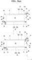
- FIG. 3A is an enlarged plan view illustrating an urged state (on the upper side of FIGs. 3A and 3B ) and an urging released state (on the lower side of FIGs. 3A and 3B ) by the urging device 23 in the one head unit in the printing part 12 illustrated in FIG. 2
- FIG. 3B is an enlarged side view corresponding to FIG. 3A .
- description of a positioning pin is omitted.
- the head unit includes the head part H including the head main body part 20 and the plate-shaped base part 21 provided at a peripheral edge of the head main body part 20 and urging device 23 for attaching the base part 21 to the line block frame 22 with the base part 21 urged toward the line block frame 22.
- the printing part 12 includes the plurality of head parts H, the line block frame 22 for supporting the base parts 21 in the head parts H from below at the same time, and the urging device 23 for attaching each of the base parts 21 to the line block frame 22 with the base part 21 urged toward the line block frame 22.
- the head main body part 20 and the base part 21 in the head part H have an integral structure.
- the seven head parts H illustrated in FIG. 2 have the same structure.
- the base part 21 in the head part H is positioned relative to the line block 22 by a reference pin 41, a pressure pin 42, and an eccentric pin 43 that are attached to the support part 22b in the line block frame 22.
- the reference pin 41 is a normal pin
- the eccentric pin 43 is a pin being rotatable and having a center at its position eccentric with respect to a rotation center
- the pressure pin 42 is a pin capable of laterally exhibiting a spring force.
- the eccentric pin 43 is also referred to as a first eccentric pin 43 or a second eccentric pin 43, as needed.
- the pressure pin 42 is also referred to as a first pressure pin 42 or a second pressure pin 42.
- the pressure pin 42 used for positioning the base part 21 includes a head part 42a and a body part 42b.
- the body part 42b contains a coil spring.
- the head part 42a When the head part 42a is laterally pressed by the base part 21, a stress based on a spring force of the coil spring is exerted.
- the head part 42a has an oval shape. Accordingly, as a stress to be exerted in a circular arc direction around a lower end of the head part 42a, not only a force in a direction toward the base part 21 but also a force for urging the base part 21 downward can be sufficiently exhibited.
- the reference pin 41 and the first eccentric pin 43 are respectively attached at a predetermined distance to positions capable of contacting a side surface on the side of one of long sides of the base part 21, and the two first pressure pins 42 are respectively attached at a predetermined distance to positions capable of contacting a side surface on the side of the other long side.
- the reference pin 41 and the one first pressure pin 42 are arranged at positions that oppose each other and the first eccentric pin 43 and the other first pressure pin 42 are arranged at positions that oppose each other, respectively, with the base part 21 interposed therebetween.
- the first pressure pin 42 urges the base part 21 in the X-direction (a direction perpendicular to a longitudinal direction).
- the base part 21 is enabled to finely adjust a position in a rotation direction around the reference pin 41, i.e., at least a position in the direction perpendicular to the longitudinal direction of the base part 21 on an XY plane.
- the second eccentric pin 43 is attached to a position capable of contacting a side surface on the side of one of short sides of the base part 21, and the second pressure pin 42 is attached to a position capable of contacting a side surface on the side of the other short side.
- the second pressure pin 42 urges the base part 21 in the Y-direction (the longitudinal direction) .
- the base part 21 is enabled to finely adjust at least a position in the longitudinal direction of the base part 21.
- a stopper 44 for preventing the eccentric pin 43 from rotating is attached to the line block frame 22 to be adjacent to the eccentric pin 43.
- the stopper 44 presses an upper surface of the eccentric pin 43 from above by tightening a locking screw.
- the base part 21 is preferably attached to the line block frame 22 by the urging device 23 with the base part 21 positioned to some extent relative to the line block frame 22.
- a position of the base part 21 is not a position that has significantly shifted. Accordingly, a time period required to finely adjust a position of the head part H can be significantly shortened.
- a force for a spring part 32, described below, in the urging device 23 to urge the base part 21 downward is preferably smaller than a force for the pressure pin 42 to laterally urge the base part 21. In this case, it is possible to finely adjust a lateral position of the base part 21 while maintaining a state where the urging device 23 urges the base part 21.
- all the head main body parts 20 have each a substantially rectangular parallelepiped shape, and are used for temporarily housing an ink and ejecting the ink.
- Each of the head main body parts 20 has a plurality of nozzles formed on its lower surface, and is enabled to eject an ink supplied thereinto from the nozzles.
- the nozzles formed on the lower surface of the head main body part 20 are exposed via the head hole parts in the line block frame 22 and the line hole part 24c in the head box 24, described above. Accordingly, the head main body part 20 is enabled to eject an ink toward the medium to be printed 10 that is conveyed below the printing part 12.
- the urging device 23 is a device for attaching the base part 21 to the line block frame 22 while urging the base part 21 toward the line block frame 22. In the head unit, even after the urging device 23 attaches the head part H to the line block frame 22, the urging by the urging device 23 is maintained.
- the urging device 23 is also enabled to forcedly release its urging force. As a result, the head part H can be easily taken out.
- the urging devices 23 are respectively arranged at diagonal positions of the base part 21. As a result, the base part 21 is urged downward with a force that is as uniform as possible by the urging devices 23 throughout its extent.
- the two urging devices 23 have the same configuration except that they respectively include bracket parts 31 having different shapes.
- the urging device 23 (the urging device at the upper right of the head unit illustrated in FIG. 3A ) including the bracket part 31 having an L shape in a top view is referred to as a "first urging device 23”
- the urging device 23 (the urging device at the lower left of the head unit illustrated in FIG. 3A ) including the bracket part 31 having a rectangular shape in a top view is hereinafter referred to as a "second urging device 23”.
- the term “urging device 23” refers to both the first urging device 23 and the second urging device 23.
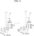
- FIG. 5 is a cross-sectional view illustrating the first urging device (on the left side in FIG. 5 ) in a urged state, taken along a line A1 - A1 illustrated in FIG. 3A , and the first urging device (on the right side in FIG. 5 ) in an urging released state, taken along a line A2 - A2 illustrated in FIG. 3A .
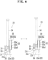
- FIG. 6 is a cross-sectional view illustrating the second urging device (on the left side in FIG. 6 ) in a urged state, taken along a line B1 - B1 illustrated in FIG. 3A , and the second urging device (on the right side in FIG. 6 ) in an urging released state, taken along a line B2 - B2 illustrated in FIG. 3A .
- the urging device 23 includes a shaft part 30 attached to the frame main body part 22a in the line block frame 22 and extending in an up-down direction, a bracket part 31 attached to the shaft part 30 via a bearing part 30a1 to enable up-down movement along the shaft part 30, a spring part 32 attached to the shaft part 30 and for urging the bracket part 31 downward, a grip part 34 attached to the bracket part 31 and protruding upward from the bracket part 31, a lock pin 33 attached to the bracket part 31 and protruding downward from the bracket part 31, and a block part 35 provided in the bracket part 31 and protruding downward from the bracket part 31.
- the shaft part 30 includes a small diameter shaft part 30a having a columnar shape extending in the up-down direction and a large diameter shaft part 30b provided on the top of the small diameter shaft part 30a and having a larger diameter than that of the small diameter shaft part 30a.
- the small diameter shaft part 30a has its lower end serving as a screw portion, and is screwed into a screw hole provided in the frame main body part 22a in the line block frame 22.
- the bearing part 30a1 (an oil-free bush) is attached to a lower portion of the small diameter shaft part 30a, and the bracket part 31 is attached thereto via the bearing part 30a1.
- the spring part 32 is attached to a middle abdomen portion of the small diameter shaft part 30a to surround the middle abdomen portion, and the spring part 32 is sandwiched between the large diameter shaft part 30b and the bracket part 31.
- the bracket part 31 has an L plate shape in a top view having a surface extending horizontally.
- the bracket part 31 has a rectangular plate shape in a top view having a surface extending horizontally.
- the urging device 23 is provided with the grip part 34, the lock pin 33, and the block part 35.
- bracket part 31 is integrated with the bearing part 30a1, the grip part 34, the lock pin 33, and the block part 35.
- the bracket part 31 is integrated with the bearing part 30a1, the grip part 34, the lock pin 33, and the block part 35, to enable up-down movement along a length of the shaft part 30 (the small diameter shaft part 30a) and rotational movement with the shaft part 30 (the small diameter shaft part 30a) as its axial center.
- bracket part 31 is attached to the small diameter shaft part 30a in the shaft part 30 via the bearing part 30a1, thereby making it possible to smoothly perform up-down movement and rotational movement.
- the spring part 32 is inserted into the small diameter shaft part 30a, and is sandwiched between the large diameter shaft part 30b and the bracket part 31, as described above. Accordingly, the spring part 32 can expand and contract by an amount corresponding to the length of the small diameter shaft part 30a.
- the spring part 32 is sandwiched between the large diameter shaft part 30b and the bracket part 31 in a contracted state. Accordingly, a downward spring force (urging force) is always applied to the bracket part 31 with the large diameter shaft part 30b as an origin.
- examples of the spring part 32 to be adopted include a coil spring (coil-shaped push spring), a leaf spring, and a disc spring.
- the spring part 32 the coil spring or the disc spring is preferably adopted, and the coil spring and the disc spring are more preferably adopted.
- the spring part 32 preferably includes a coil spring 32a and a disc spring 32b arranged on the underside of the coil spring 32a to be continuous from the coil spring 32a.
- the spring part 32 is enabled to easily adjust a spring force.
- the coil spring 32a urges the bracket part 31 via the disc spring 32b. Accordingly, the coil spring 32a does not directly urge only the bearing part 30a1, whereby the bearing part 30a1 can be prevented from shifting in the up-down direction relative to the bracket part 31.
- the lock pin 33 has a columnar shape, and has its upper end attached and fixed to the bracket part 31 with a fastener such as a bolt.
- the lock pin 33 has its lower end being flat, and is arranged at an urging position 21a on the base part 21 at the time of urging and is arranged at a standby position 22c on the line block frame 22 at the time of releasing urging.
- the standby position 22c is a blind hole provided in the line block frame 22 (see FIGs. 3A and 3B ) and provided on the upper surface side of the line block frame 22.
- an upper end surface 22c1 of the blind hole is positioned above a lower end surface 33a of the lock pin 33 in a case where the lock pin 33 is arranged at the standby position 22c.
- the lock pin 33 arranged at the standby position 22c contacts a wall around the blind hole, whereby the bracket part 31 can be prevented from randomly rotationally moving.
- the grip part 34 has a columnar shape, is arranged between the shaft part 30 and the lock pin 33, has its lower end serving as a screw portion, and is screwed into a screw hole provided in the bracket part 31. Accordingly, when the grip part 34 is lifted, the grip part 34, the bracket part 31, the bearing part 30a1, the lock pin 33, and the block part 35 are integrally lifted.
- the grip part 34 is provided to protrude upward from the bracket part 31, and has its upper end positioned above the large diameter shaft part 30b. Accordingly, in the urging device 23, the grip part 34 is easily gripped.
- the grip part 34 makes it easy to lift the bracket part 31 and the lock pin 33, thereby making it possible to easily perform up-down movement of the bracket part 31 relative to the shaft part 30 and rotational movement of the bracket part 31 with the shaft part 30 as its axis.
- the block part 35 is formed integrally with the bracket part 31.
- the block part 35 has a block shape, and is arranged on the upper surface of the frame main body part 22a when the lock pin 33 is arranged at the standby position 22c. As a result, the entire urging device 23 is supported by the block part 35.
- a lower surface of the lock pin 33 is preferably in a floating state where it does not contact a bottom surface of the blind hole as the standby position 22c and is spaced apart therefrom by a predetermined distance. This makes it possible to prevent the lower surface of the lock pin 33 from being damaged due to friction or the like.
- FIG. 7 is an explanatory diagram for illustrating respective operations at the time of urging (on the left side of FIG. 7 ) and at the time of releasing urging (on the right side in FIG. 7 ) by the first urging device in the head unit illustrated in FIG. 3A and 3B
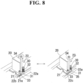
- FIG. 8 is an explanatory diagram for illustrating respective operations at the time of urging (on the left side in FIG. 8 ) and at the time of releasing urging (on the right side in FIG. 8 ) by the second urging device in the head unit illustrated in FIGs. 3A and 3B .
- the lock pin 33 in the urging device 23 is arranged at the urging position 21a on the base part 21 at the time of urging.
- bracket part 31 is urged downward by the spring part 32. Accordingly, the base part 21 is urged toward the support part 22b in the line block frame 22 therebelow via the lock pin 33.
- Such rotational movement is performed from a position where the lock pin 33 is above the urging position 21a to a position where the lock pin 33 is above the standby position 22c.
- the block part 35 provided in the bracket part 31 is arranged on the upper surface of the frame main body part 22a in the line block frame 22.
- the urging device 23 enters a state where it is supported by the frame main body part 22a.
- a force for urging the bracket part 31 is due to the spring part 32. Accordingly, every time the head part H is attached, almost the same urging force is applied to the base part 21.
- the bracket part 31 is rotationally moved around the shaft part 30 to allow the lock pin 33 to laterally escape to the standby position 22c, thereby making it possible to more easily attach and detach the head part H.
- the ink jet printing apparatus 100 includes the paper feeding part 11, the printing part 12, the drying part 13, and the recovery part 14, the paper feeding part 11, the drying part 13, and the recovery part 14 may be respectively separate members.
- the one line block frame 22 having the head part H mounted thereon is attached to the bottom plate part 24b in the head box 24, a plurality of line block frames each having head parts H mounted thereon may be attached.
- the head parts H are attached at seven positions to have a staggered shape in a top view to the line block frame 22 in the ink jet printing apparatus 100 according to the present embodiment, the number of head parts H and a position to which each of the head parts H is attached are not limited to these.
- a positioning method is not limited to this.
- Positions where the urging devices 23 are provided are not respectively limited to diagonal positions of the base part 21 either.
- Both a side surface of the block part 35 and a side surface of the frame main body part 22a in the line block frame 22 may contact each other, although a space is formed therebetween at the time of urging when the lock pin 33 is arranged on the base part 21 in the ink jet printing apparatus 100 according to the present embodiment.
Landscapes
- Ink Jet (AREA)
- Common Mechanisms (AREA)
Applications Claiming Priority (1)
| Application Number | Priority Date | Filing Date | Title |
|---|---|---|---|
| JP2023161699A JP2025052794A (ja) | 2023-09-25 | 2023-09-25 | インクジェット印字装置 |
Publications (2)
| Publication Number | Publication Date |
|---|---|
| EP4527632A1 true EP4527632A1 (de) | 2025-03-26 |
| EP4527632B1 EP4527632B1 (de) | 2026-02-25 |
Family
ID=92791836
Family Applications (1)
| Application Number | Title | Priority Date | Filing Date |
|---|---|---|---|
| EP24199892.1A Active EP4527632B1 (de) | 2023-09-25 | 2024-09-12 | Tintenstrahldruckvorrichtung |
Country Status (4)
| Country | Link |
|---|---|
| US (1) | US20250100308A1 (de) |
| EP (1) | EP4527632B1 (de) |
| JP (1) | JP2025052794A (de) |
| CN (1) | CN119682388A (de) |
Citations (5)
| Publication number | Priority date | Publication date | Assignee | Title |
|---|---|---|---|---|
| JP2010173232A (ja) | 2009-01-30 | 2010-08-12 | Miyakoshi Printing Machinery Co Ltd | インクジェット記録装置 |
| JP2011152708A (ja) | 2010-01-27 | 2011-08-11 | Miyakoshi Printing Machinery Co Ltd | インクジェット印字装置 |
| US20110239431A1 (en) * | 2008-02-08 | 2011-10-06 | Seiko Epson Corporation | Head unit, liquid jet device, and method for adjusting position of liquid jet head |
| US20200384763A1 (en) * | 2019-06-07 | 2020-12-10 | Sii Printek Inc. | Liquid jet head and liquid jet recording device |
| WO2023164423A1 (en) * | 2022-02-22 | 2023-08-31 | Kateeva, Inc. | Print tile and printhead assembly for inkjet printer |
-
2023
- 2023-09-25 JP JP2023161699A patent/JP2025052794A/ja active Pending
-
2024
- 2024-09-12 EP EP24199892.1A patent/EP4527632B1/de active Active
- 2024-09-13 CN CN202411285548.5A patent/CN119682388A/zh active Pending
- 2024-09-24 US US18/894,643 patent/US20250100308A1/en active Pending
Patent Citations (5)
| Publication number | Priority date | Publication date | Assignee | Title |
|---|---|---|---|---|
| US20110239431A1 (en) * | 2008-02-08 | 2011-10-06 | Seiko Epson Corporation | Head unit, liquid jet device, and method for adjusting position of liquid jet head |
| JP2010173232A (ja) | 2009-01-30 | 2010-08-12 | Miyakoshi Printing Machinery Co Ltd | インクジェット記録装置 |
| JP2011152708A (ja) | 2010-01-27 | 2011-08-11 | Miyakoshi Printing Machinery Co Ltd | インクジェット印字装置 |
| US20200384763A1 (en) * | 2019-06-07 | 2020-12-10 | Sii Printek Inc. | Liquid jet head and liquid jet recording device |
| WO2023164423A1 (en) * | 2022-02-22 | 2023-08-31 | Kateeva, Inc. | Print tile and printhead assembly for inkjet printer |
Also Published As
| Publication number | Publication date |
|---|---|
| CN119682388A (zh) | 2025-03-25 |
| US20250100308A1 (en) | 2025-03-27 |
| JP2025052794A (ja) | 2025-04-07 |
| EP4527632B1 (de) | 2026-02-25 |
Similar Documents
| Publication | Publication Date | Title |
|---|---|---|
| US8833252B2 (en) | Screen printing apparatus | |
| JP2012161992A (ja) | 液滴吐出ヘッドの位置決め機構、液滴吐出装置、画像形成装置、液滴吐出ヘッドの位置決め方法ならびに交換方法 | |
| US9802409B2 (en) | Adjustment mechanism and adjustment method | |
| US20030063154A1 (en) | Liquid droplet patterning apparatus | |
| JP2012101540A (ja) | インク式印刷機器において少なくとも1つのプリントバーを印刷位置に位置決めする装置 | |
| EP2875961B1 (de) | Zeilendrucker und Druckkopfbewegungsverfahren eines Zeilendruckers | |
| DE102014212664A1 (de) | Luftkissen-trägervorrichtung für einen tintenstrahldrucker | |
| JP2011062681A (ja) | マルチインクジェットヘッドパッケージ、これを用いるインクジェット記録装置及びマルチインクジェットヘッドパッケージをそのインクジェット記録装置に整列させる方法 | |
| JPWO2019044031A1 (ja) | 記録ヘッドのノズル位置調整装置 | |
| CN112046155B (zh) | 液体喷射头以及液体喷射记录装置 | |
| EP4527632B1 (de) | Tintenstrahldruckvorrichtung | |
| KR20180051858A (ko) | 잉크젯 헤드 정렬 장치 및 이를 포함하는 액적 토출 장치 | |
| JP2012250454A (ja) | 画像形成装置 | |
| CN101391520B (zh) | 液体喷射装置 | |
| JP5178555B2 (ja) | 記録ヘッドの位置調整方法 | |
| US20110074898A1 (en) | Web printer and support structure | |
| JP2003154724A (ja) | インクジェットプリンタ | |
| EP1636037B1 (de) | Neigungskopfreiniger | |
| CN110561913B (zh) | 行式喷头单元 | |
| US10556452B2 (en) | Printing apparatus and method of positioning support section | |
| US20220281247A1 (en) | Head unit, head unit adjustment method, attaching/ detaching jig and head unit exchange method | |
| JP7689883B2 (ja) | ヘッドユニットおよびヘッドユニットの調整方法 | |
| US12304226B2 (en) | Head unit position adjustment method | |
| JP7122611B2 (ja) | ラインヘッドユニット | |
| CN112441455A (zh) | 印刷装置 |
Legal Events
| Date | Code | Title | Description |
|---|---|---|---|
| PUAI | Public reference made under article 153(3) epc to a published international application that has entered the european phase |
Free format text: ORIGINAL CODE: 0009012 |
|
| STAA | Information on the status of an ep patent application or granted ep patent |
Free format text: STATUS: THE APPLICATION HAS BEEN PUBLISHED |
|
| AK | Designated contracting states |
Kind code of ref document: A1 Designated state(s): AL AT BE BG CH CY CZ DE DK EE ES FI FR GB GR HR HU IE IS IT LI LT LU LV MC ME MK MT NL NO PL PT RO RS SE SI SK SM TR |
|
| STAA | Information on the status of an ep patent application or granted ep patent |
Free format text: STATUS: REQUEST FOR EXAMINATION WAS MADE |
|
| 17P | Request for examination filed |
Effective date: 20250627 |
|
| GRAP | Despatch of communication of intention to grant a patent |
Free format text: ORIGINAL CODE: EPIDOSNIGR1 |
|
| STAA | Information on the status of an ep patent application or granted ep patent |
Free format text: STATUS: GRANT OF PATENT IS INTENDED |
|
| INTG | Intention to grant announced |
Effective date: 20251014 |
|
| RIC1 | Information provided on ipc code assigned before grant |
Ipc: B41J 25/00 20060101AFI20251003BHEP Ipc: B41J 25/34 20060101ALI20251003BHEP |
|
| GRAS | Grant fee paid |
Free format text: ORIGINAL CODE: EPIDOSNIGR3 |
|
| GRAA | (expected) grant |
Free format text: ORIGINAL CODE: 0009210 |
|
| STAA | Information on the status of an ep patent application or granted ep patent |
Free format text: STATUS: THE PATENT HAS BEEN GRANTED |
|
| AK | Designated contracting states |
Kind code of ref document: B1 Designated state(s): AL AT BE BG CH CY CZ DE DK EE ES FI FR GB GR HR HU IE IS IT LI LT LU LV MC ME MK MT NL NO PL PT RO RS SE SI SK SM TR |
|
| REG | Reference to a national code |
Ref country code: CH Ref legal event code: F10 Free format text: ST27 STATUS EVENT CODE: U-0-0-F10-F00 (AS PROVIDED BY THE NATIONAL OFFICE) Effective date: 20260225 Ref country code: GB Ref legal event code: FG4D |
|
| REG | Reference to a national code |
Ref country code: DE Ref legal event code: R096 Ref document number: 602024002814 Country of ref document: DE |
|
| REG | Reference to a national code |
Ref country code: IE Ref legal event code: FG4D |
|
| P01 | Opt-out of the competence of the unified patent court (upc) registered |
Free format text: CASE NUMBER: UPC_APP_0006128_4527632/2026 Effective date: 20260219 |