EP4527660A1 - Dispositif d'affichage contextuel et véhicule - Google Patents
Dispositif d'affichage contextuel et véhicule Download PDFInfo
- Publication number
- EP4527660A1 EP4527660A1 EP22962832.6A EP22962832A EP4527660A1 EP 4527660 A1 EP4527660 A1 EP 4527660A1 EP 22962832 A EP22962832 A EP 22962832A EP 4527660 A1 EP4527660 A1 EP 4527660A1
- Authority
- EP
- European Patent Office
- Prior art keywords
- pinion gear
- display panel
- gear
- state
- display device
- Prior art date
- Legal status (The legal status is an assumption and is not a legal conclusion. Google has not performed a legal analysis and makes no representation as to the accuracy of the status listed.)
- Pending
Links
Images




Classifications
-
- B—PERFORMING OPERATIONS; TRANSPORTING
- B60—VEHICLES IN GENERAL
- B60K—ARRANGEMENT OR MOUNTING OF PROPULSION UNITS OR OF TRANSMISSIONS IN VEHICLES; ARRANGEMENT OR MOUNTING OF PLURAL DIVERSE PRIME-MOVERS IN VEHICLES; AUXILIARY DRIVES FOR VEHICLES; INSTRUMENTATION OR DASHBOARDS FOR VEHICLES; ARRANGEMENTS IN CONNECTION WITH COOLING, AIR INTAKE, GAS EXHAUST OR FUEL SUPPLY OF PROPULSION UNITS IN VEHICLES
- B60K35/00—Instruments specially adapted for vehicles; Arrangement of instruments in or on vehicles
- B60K35/50—Instruments characterised by their means of attachment to or integration in the vehicle
- B60K35/53—Movable instruments, e.g. slidable
-
- B—PERFORMING OPERATIONS; TRANSPORTING
- B60—VEHICLES IN GENERAL
- B60R—VEHICLES, VEHICLE FITTINGS, OR VEHICLE PARTS, NOT OTHERWISE PROVIDED FOR
- B60R11/00—Arrangements for holding or mounting articles, not otherwise provided for
- B60R11/02—Arrangements for holding or mounting articles, not otherwise provided for for radio sets, television sets, telephones, or the like; Arrangement of controls thereof
- B60R11/0229—Arrangements for holding or mounting articles, not otherwise provided for for radio sets, television sets, telephones, or the like; Arrangement of controls thereof for displays, e.g. cathodic tubes
- B60R11/0235—Arrangements for holding or mounting articles, not otherwise provided for for radio sets, television sets, telephones, or the like; Arrangement of controls thereof for displays, e.g. cathodic tubes of flat type, e.g. LCD
-
- H—ELECTRICITY
- H02—GENERATION; CONVERSION OR DISTRIBUTION OF ELECTRIC POWER
- H02K—DYNAMO-ELECTRIC MACHINES
- H02K7/00—Arrangements for handling mechanical energy structurally associated with dynamo-electric machines, e.g. structural association with mechanical driving motors or auxiliary dynamo-electric machines
- H02K7/10—Structural association with clutches, brakes, gears, pulleys or mechanical starters
- H02K7/116—Structural association with clutches, brakes, gears, pulleys or mechanical starters with gears
-
- B—PERFORMING OPERATIONS; TRANSPORTING
- B60—VEHICLES IN GENERAL
- B60K—ARRANGEMENT OR MOUNTING OF PROPULSION UNITS OR OF TRANSMISSIONS IN VEHICLES; ARRANGEMENT OR MOUNTING OF PLURAL DIVERSE PRIME-MOVERS IN VEHICLES; AUXILIARY DRIVES FOR VEHICLES; INSTRUMENTATION OR DASHBOARDS FOR VEHICLES; ARRANGEMENTS IN CONNECTION WITH COOLING, AIR INTAKE, GAS EXHAUST OR FUEL SUPPLY OF PROPULSION UNITS IN VEHICLES
- B60K35/00—Instruments specially adapted for vehicles; Arrangement of instruments in or on vehicles
- B60K35/20—Output arrangements, i.e. from vehicle to user, associated with vehicle functions or specially adapted therefor
- B60K35/21—Output arrangements, i.e. from vehicle to user, associated with vehicle functions or specially adapted therefor using visual output, e.g. blinking lights or matrix displays
- B60K35/22—Display screens
-
- B—PERFORMING OPERATIONS; TRANSPORTING
- B60—VEHICLES IN GENERAL
- B60K—ARRANGEMENT OR MOUNTING OF PROPULSION UNITS OR OF TRANSMISSIONS IN VEHICLES; ARRANGEMENT OR MOUNTING OF PLURAL DIVERSE PRIME-MOVERS IN VEHICLES; AUXILIARY DRIVES FOR VEHICLES; INSTRUMENTATION OR DASHBOARDS FOR VEHICLES; ARRANGEMENTS IN CONNECTION WITH COOLING, AIR INTAKE, GAS EXHAUST OR FUEL SUPPLY OF PROPULSION UNITS IN VEHICLES
- B60K35/00—Instruments specially adapted for vehicles; Arrangement of instruments in or on vehicles
- B60K35/50—Instruments characterised by their means of attachment to or integration in the vehicle
-
- B—PERFORMING OPERATIONS; TRANSPORTING
- B60—VEHICLES IN GENERAL
- B60K—ARRANGEMENT OR MOUNTING OF PROPULSION UNITS OR OF TRANSMISSIONS IN VEHICLES; ARRANGEMENT OR MOUNTING OF PLURAL DIVERSE PRIME-MOVERS IN VEHICLES; AUXILIARY DRIVES FOR VEHICLES; INSTRUMENTATION OR DASHBOARDS FOR VEHICLES; ARRANGEMENTS IN CONNECTION WITH COOLING, AIR INTAKE, GAS EXHAUST OR FUEL SUPPLY OF PROPULSION UNITS IN VEHICLES
- B60K35/00—Instruments specially adapted for vehicles; Arrangement of instruments in or on vehicles
- B60K35/55—Instruments with parts that can change their shape or position to configure an active screen, e.g. by folding or by rolling
-
- F—MECHANICAL ENGINEERING; LIGHTING; HEATING; WEAPONS; BLASTING
- F16—ENGINEERING ELEMENTS AND UNITS; GENERAL MEASURES FOR PRODUCING AND MAINTAINING EFFECTIVE FUNCTIONING OF MACHINES OR INSTALLATIONS; THERMAL INSULATION IN GENERAL
- F16H—GEARING
- F16H19/00—Gearings comprising essentially only toothed gears or friction members and not capable of conveying indefinitely-continuing rotary motion
- F16H19/02—Gearings comprising essentially only toothed gears or friction members and not capable of conveying indefinitely-continuing rotary motion for interconverting rotary or oscillating motion and reciprocating motion
- F16H19/04—Gearings comprising essentially only toothed gears or friction members and not capable of conveying indefinitely-continuing rotary motion for interconverting rotary or oscillating motion and reciprocating motion comprising a rack
-
- H—ELECTRICITY
- H02—GENERATION; CONVERSION OR DISTRIBUTION OF ELECTRIC POWER
- H02K—DYNAMO-ELECTRIC MACHINES
- H02K7/00—Arrangements for handling mechanical energy structurally associated with dynamo-electric machines, e.g. structural association with mechanical driving motors or auxiliary dynamo-electric machines
- H02K7/003—Couplings; Details of shafts
-
- B—PERFORMING OPERATIONS; TRANSPORTING
- B60—VEHICLES IN GENERAL
- B60R—VEHICLES, VEHICLE FITTINGS, OR VEHICLE PARTS, NOT OTHERWISE PROVIDED FOR
- B60R11/00—Arrangements for holding or mounting articles, not otherwise provided for
- B60R2011/0001—Arrangements for holding or mounting articles, not otherwise provided for characterised by position
- B60R2011/0003—Arrangements for holding or mounting articles, not otherwise provided for characterised by position inside the vehicle
- B60R2011/0005—Dashboard
-
- B—PERFORMING OPERATIONS; TRANSPORTING
- B60—VEHICLES IN GENERAL
- B60R—VEHICLES, VEHICLE FITTINGS, OR VEHICLE PARTS, NOT OTHERWISE PROVIDED FOR
- B60R11/00—Arrangements for holding or mounting articles, not otherwise provided for
- B60R2011/0042—Arrangements for holding or mounting articles, not otherwise provided for characterised by mounting means
- B60R2011/008—Adjustable or movable supports
- B60R2011/0084—Adjustable or movable supports with adjustment by linear movement in their operational position
-
- B—PERFORMING OPERATIONS; TRANSPORTING
- B60—VEHICLES IN GENERAL
- B60R—VEHICLES, VEHICLE FITTINGS, OR VEHICLE PARTS, NOT OTHERWISE PROVIDED FOR
- B60R11/00—Arrangements for holding or mounting articles, not otherwise provided for
- B60R2011/0042—Arrangements for holding or mounting articles, not otherwise provided for characterised by mounting means
- B60R2011/008—Adjustable or movable supports
- B60R2011/0092—Adjustable or movable supports with motorization
-
- B—PERFORMING OPERATIONS; TRANSPORTING
- B60—VEHICLES IN GENERAL
- B60Y—INDEXING SCHEME RELATING TO ASPECTS CROSS-CUTTING VEHICLE TECHNOLOGY
- B60Y2400/00—Special features of vehicle units
- B60Y2400/40—Actuators for moving a controlled member
- B60Y2400/405—Electric motors actuators
-
- B—PERFORMING OPERATIONS; TRANSPORTING
- B60—VEHICLES IN GENERAL
- B60Y—INDEXING SCHEME RELATING TO ASPECTS CROSS-CUTTING VEHICLE TECHNOLOGY
- B60Y2400/00—Special features of vehicle units
- B60Y2400/70—Gearings
-
- B—PERFORMING OPERATIONS; TRANSPORTING
- B60—VEHICLES IN GENERAL
- B60Y—INDEXING SCHEME RELATING TO ASPECTS CROSS-CUTTING VEHICLE TECHNOLOGY
- B60Y2400/00—Special features of vehicle units
- B60Y2400/92—Driver displays
Definitions
- the present disclosure relates to a display device, and more particularly, to a pop-up display device that protrudes when needed.
- a vehicle includes various input and output components as a device for user interfaces.
- input components have mainly consisted of mechanical parts such as buttons, dials, and levers.
- mechanical parts such as buttons, dials, and levers.
- voice input touch input
- touch input touch input
- gesture input even gesture input
- a cluster which includes a dashboard providing information on a vehicle speed, revolutions per minute (RPM), and fuel level, has been used as the most basic output component.
- RPM revolutions per minute
- a cluster which includes a dashboard providing information on a vehicle speed, revolutions per minute (RPM), and fuel level, has been used as the most basic output component.
- display technology improves and vehicle functions become more precise and diversified, more vehicles are being equipped with display units to output various types of information.
- HUD head-up display
- the display not only outputs information but also includes touch sensors to enable touch input simultaneously.
- the display is capable of functioning as both an output and input component. As a result, the size of displays used in vehicles is becoming larger.
- an instrument panel including the dashboard and center fascia which is located at the front of the vehicle, may obstruct the front view as the size thereof increases. Additionally, with the advancement of autonomous driving technology, the function of the instrument panel to provide information may become unnecessary or reduced during autonomous driving. Therefore, a larger instrument panel is not always better.
- the present disclosure aims to provide a display device that extends upward, and more particularly, a display device for minimizing the height of a rear cover that covers a driver by reducing the length of a rack gear relative to a stroke length.
- the present disclosure aims to provide an instrument panel that is positioned in front of a driver and is capable of being retracted or extended. Specifically, the present disclosure aims to provide a display device capable of being extended when needed and reduced in size to ensure an unobstructed front view.
- a display device configured to display images on a front side; and a driver coupled to a rear side of the display panel and configured to move the display panel in a vertical direction.
- the driver comprises: a motor configured to provide rotational power; a pinion gear module configured to rotate by receiving the rotational power from the motor and comprising a first pinion gear and a second pinion gear arranged parallel in the vertical direction; and a rack gear located at the rear side of the display panel, extending in the vertical direction, and maintaining engagement with at least one of the first pinion gear or the second pinion gear.
- the display panel moves upward to transition from a first state to a second state.
- the rack gear engages with the first pinion gear
- the rack gear engages with the second pinion gear.
- a length of the rack gear is shorter than a distance the display panel moves to transition from the first state to the second state.
- the pinion gear module further comprises a third pinion gear located between the first pinion gear and the second pinion gear and configured to synchronize the first pinion gear and the second pinion gear to rotate in a same direction.
- the third pinion gear is positioned more toward a rear side than the first pinion gear and the second pinion gear.
- the display device includes a fixed cover coupled to the rear side of the display panel and configured to cover the driver. In the second state, an upper end of the fixed cover is located above an upper end of the rack gear.
- the display device includes: a guide rail fixed to the fixed cover and extending in the vertical direction; and a guide block coupled to the rear side of the display panel and configured to move along the guide rail.
- the driver comprises: a worm gear coupled to the motor; a helical gear configured to engage with and rotate along with the worm gear, wherein the helical gear is configured to rotate around an axis extending perpendicular to a rotational axis of the motor; and a horizontal shaft configured to engage with and rotate along with the helical gear and extending in a horizontal direction.
- the pinion gear module is configured receive the rotational power from the motor via the horizontal shaft.
- the rack gear and the pinion gear module are provided on each side of the display panel, and the horizontal shaft extends to each side of the display panel and is connected with the pinion gear module at each end.
- the first pinion gear is configured to rotate around the horizontal shaft.
- the display device further comprises a third pinion gear located between the first pinion gear and the second pinion gear and configured to synchronize the first pinion gear and the second pinion gear to rotate in a same direction.
- a vehicle in another aspect of the present disclosure, includes: a dashboard located at a front interior of the vehicle and having a horizontally elongated opening; a display panel configured to retract and extend through the opening; and a driver coupled to a rear side of the display panel and configured to move the display panel upward and downward.
- the driver comprises: a motor configured to provide rotational power; a pinion gear module configured to rotate by receiving the rotational power from the motor and comprising a first pinion gear and a second pinion gear arranged parallel in a vertical direction; and a rack gear located at the rear side of the display panel, extending in the vertical direction, and maintaining engagement with at least one of the first pinion gear or the second pinion gear.
- the display panel moves upward to transition from a first state to a second state.
- a first state an upper part of the display panel is exposed outside the opening
- a second state an area of the display panel exposed outside the opening reaches a maximum.
- the pinion gear module further comprises a third pinion gear located between the first pinion gear and the second pinion gear and configured to synchronize the first pinion gear and the second pinion gear to rotate in a same direction.
- the rack gear engages with the first pinion gear
- the rack gear engages with the second pinion gear.
- a length of the rack gear is shorter than a distance the display panel moves to transition from the first state to the second state.
- the vehicle comprises a fixed cover coupled to the rear side of the display panel and configured to cover the driver.
- a fixed cover coupled to the rear side of the display panel and configured to cover the driver.
- an upper end of the fixed cover is located above an upper end of the rack gear.
- a display device of the present disclosure reduces the height of a driver at the rear side thereof, thereby minimizing the size of a fixed cover.
- an instrument panel applied to vehicles may adjust the size, thereby facilitating an unobstructed front view and providing a sense of openness.
- a singular representation may include a plural representation unless it represents a definitely different meaning from the context.
- FIG. 1 is a view showing a state in which a display device 100 according to an embodiment of the present disclosure is mounted as an instrument panel of a vehicle.
- the display device 100 of the present disclosure may be mounted in a vehicle.
- the display device 100 may be positioned on a dashboard located at the front interior of the vehicle.
- the present disclosure is not limited thereto, and the display device 100 may also be positioned in the rear seats of the vehicle or on the sides of the vehicle.
- the display device 100 may be installed not only in vehicles but also on stationary devices.
- the display device 100 needs to change the size thereof by retracting or extending as needed. Therefore, the following explanation will focus on the display device 100 mounted in the vehicle, particularly as the instrument panel located on the dashboard as shown in FIG. 1 .
- the vehicle equipped with the display device 100 may be an autonomous driving vehicle.
- the vehicle may switch between an autonomous driving mode and a manual mode based on a user input. For example, the vehicle may switch from the manual mode to the autonomous driving mode or from the autonomous driving mode to the manual mode based on the user input received through a user interface device.
- the vehicle may switch between the autonomous driving mode and manual mode based on driving situation information.
- the driving situation information may include at least one of external object information, navigation information, or vehicle status information.
- the autonomous vehicle may operate driven based on the operation system.
- the autonomous vehicle may operate based on information, data, or signals generated by the driving system, departure system, or parking system.
- the autonomous vehicle may receive a user input for driving through a driving control device. Based on the user input received via the driving control device, the vehicle may be operated.
- the information provided varies depending on the driving mode of the vehicle, and the size of a display unit may change depending on the provided information.
- the vehicle may be equipped with the display device 100 capable of varying in size depending on the situation, thereby ensuring a sense of openness at the front while providing a larger screen when needed.
- the display device 100 of the present disclosure may include a display panel 110 that retracts and extends through an opening 15 formed on a dashboard 10 and a driver 130 that moves the display panel 110 vertically.
- the present disclosure is described based on a form where the display panel 110 is extended from the lower side to the upper side, but the display panel 110 may also be extended horizontally or from the upper side to the lower side.
- the opening 15 may be formed on the dashboard 10, and the storage space for the driver 130 and the display panel 110 may be arranged beneath the dashboard 10.
- FIG. 1(a) shows a first state
- FIG. 1(b) shows a second state
- the first state the upper part of the display panel 110 is partially exposed.
- the display panel 110 moves upward and transitions to the second state.
- the second state the lower part of the display panel 110 is also exposed upward to allow the display panel 110 to expand to the maximum screen size.
- the display panel 110 may display graphic objects corresponding to various types of information.
- the display panel 110 may include at least one of a liquid crystal display (LCD), a thin film transistor-liquid crystal display (TFT LCD), an organic light-emitting diode (OLED), a flexible display, a three-dimensional (3D) display, or an electronic ink (e-ink) display.
- LCD liquid crystal display
- TFT LCD thin film transistor-liquid crystal display
- OLED organic light-emitting diode
- a flexible display a three-dimensional (3D) display
- 3D three-dimensional
- e-ink electronic ink
- the display panel 110 may form a layered structure or be integrated with a touch input unit 213, thereby implementing a touch screen.
- the display panel 110 may include a transparent display.
- the transparent display may be attached to the windshield or window.
- FIG. 2 is a cross-sectional view along lines A-A and B-B of FIG. 1 .
- the driver 130 located on the rear side of the display panel 110, may be positioned inside the dashboard 10.
- the dashboard 10 may be composed of two layers where the part closer to the driver is lower and the front part is higher.
- the front and rear parts of the dashboard 10 may have a step difference, and the opening 15 through which the display panel 110 extends or retracts may be located between a first dashboard 11 and a second dashboard 12.
- the second dashboard 12 which is located in the rear direction of the display panel 110, has a step difference from the first dashboard 11, thereby allowing a fixed cover 120, which is positioned at the rear side of the display device 100, to be aligned with the location of the second dashboard 12.
- the fixed cover 120 covers the driver 130, which moves the display panel 110 in the vertical direction.
- Components such as a motor 131 and a pinion gear
- that remain stationary in the driver 130 may be fixed.
- the driver 130 is mounted inside the dashboard 10 and may partially protrude above the opening 15. However, the driver 130 is mostly covered by the second dashboard 12 or has minimal exposure.
- FIG. 2(a) shows the first state (cross-sectional view along line A-A).
- the fixed cover 120 or driver 130 is not located at the rear side of a portion of the display unit protruding above the second dashboard, thereby allowing the display device 100 to maintain a slim appearance.
- FIG. 2(b) shows the second state (cross-sectional view along line B-B).
- the display panel 110 moves upward.
- the fixed cover 120 may be positioned above the lower end of the display panel 110 to cover the components (such as a rack gear 137) of the driver 130 located at the rear side of the display panel 110.
- the vertical height of the fixed cover 120 should be greater than or equal to the movement distance of the display panel 110 and the length of the rack gear 137. This will be explained in detail with reference to FIG. 7 .
- FIG. 3 is a rear perspective view of the display device 100 according to an embodiment of the present disclosure.
- A corresponds to a position aligned with the upper side of the first dashboard 11
- B corresponds to a position aligned with the upper side of the second dashboard 12.
- the upper part of A is visible to a user seated in the vehicle, while the upper part of B is visible when viewed from the rear side of the display device 100 (from the front of the vehicle).
- the present disclosure aims to improve the structure of the driver 130 that moves the display panel 110 to reduce the size of the fixed cover 120.
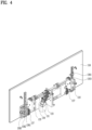
- FIG. 4 is a view showing the driver 130 of the display device 100 according to an embodiment of the present disclosure.
- FIG. 4 shows the driver 130 located at the rear side of the display panel 110 in the state with the fixed cover 120 removed in FIG. 3(a) .
- the driver 130 may include the motor 131 that provides rotational power, the pinion gear that rotates by receiving the rotational power from the motor 131, and the rack gear 137 that engages with the pinion gear and moves linearly when the pinion gear rotates.
- the display panel 110 of the present disclosure is elongated in the horizontal direction.
- the display panel 110 may be equipped with a pair of rack gears 137 on the left and right sides to ensure smooth movement without twisting.
- a horizontal shaft 134 which is elongated in the horizontal direction, may be used to transmit the power from the single motor 131 to both sides.
- the motor 131 may also be arranged to rotate along a horizontal axis. However, when the motor 131 rotates, the axis may be subjected to loads due to gravity. Therefore, as shown in FIG. 4 , the axis of the motor may be positioned vertically, and the rotational force along the vertical axis may be transferred into the rotational force along the horizontal axis.
- FIG. 5 is an enlarged view of the motor 131.
- FIG. 5 shows a worm gear 132 attached to the axis of the motor 131 and a helical gear 133 that engages and rotates with the worm gear 132.
- the worm gear 132 is implemented as a bar with a screw-shaped outer surface.
- the gear that engages with the worm gear 132 may rotate around an axis in a direction different from the rotational axis of the worm gear 132 (generally along a vertical axis).
- the rotational axis of the helical gear 133 is extended in the horizontal direction.
- the helical gear 133 is used.
- the helical gear 133 has twisted teeth, which provide better engagement than the spur gear, and thus, the helical gear 133 generates less noise and is advantageous for power transmission.
- multiple gears are provided to adjust the rotational speed of the horizontal shaft 134 relative to the rotational speed of the motor 131.
- the horizontal shaft 134 extends in the left and right directions, and a pair of gear modules are located at the ends of the horizontal shaft 134 on both sides. Since the gear module has a symmetrical structure on both sides, the explanation will be based on one gear module.
- FIG. 6 is a view showing a pinion gear module 135 of the display device 100 according to an embodiment of the present disclosure.
- the pinion gear module 135 includes multiple pinion gears 1351, 1352, and 1353, and the horizontal shaft 134 is connected to one of these pinion gears to transmit rotational power.
- a second pinion gear 1352 which is located at the top, is connected to the horizontal shaft 134, and a first pinion gear 1351 is positioned below the second pinion gear 1352.
- a third pinion gear 1353 which is located between the first and second pinion gears, may be further included.
- the horizontal shaft 134 may also be coupled with the first pinion gear 1351 or the third pinion gear 1353.
- the first pinion gear 1351 and the second pinion gear 1352 are positioned in the same horizontal location but are spaced apart vertically.
- the third pinion gear 1353 may be located between the first pinion gear 1351 and the second pinion gear 1352.
- the rotation direction of the third pinion gear 1353 differs from those of the first pinion gear 1351 and the second pinion gear 1352. If the third pinion gear 1353 comes into contact with the rack gear 137, the vertical movement of the rack gear 137 may be restricted. Thus, compared to the first pinion gear 1351 or the second pinion gear 1352, the third pinion gear 1353 may be positioned slightly toward the rear side to avoid contact with the rack gear 137.
- FIG. 7 is a view showing the positions of the pinion gear and the rack gear 137 in the first and second states of the display device 100 according to an embodiment of the present disclosure.
- FIG. 7(a) shows the first state. In the first state, the rack gear 137 engages with the first pinion gear 1351.
- FIG. 7(b) shows the second state. In FIG. 7(b) , the rack gear 137 engages with the second pinion gear 1352.
- the rack gear 137 When transitioning from the first state to the second state, the rack gear 137 initially engages with both the first pinion gear 1351 and the second pinion gear 1352 while engaging with the first pinion gear 1351. Finally, the rack gear 137 engages only with the second pinion gear 1352, and the transition to the second state is completed.
- the rack gear 137 is capable of being driven by engaging with either the first pinion gear 1351 or the second pinion gear 1352.
- the upper part of the rack gear 137 engages with the first pinion gear 1351
- the lower part of the rack gear 137 engages with the second pinion gear 1352. Therefore, the length r1 of the rack gear 137 may be shorter than the movement distance d.
- FIG. 8 is a view showing the driver 130 when there is only a single pinion gear.
- the rack gear 137 needs to remain engaged with the single pinion gear in both the first and second states. Therefore, the length r2 of the rack gear 137 should be longer than the movement distance d. In other words, in addition to the movement distance, the rack gear 137 requires an extra length corresponding to a space for the rack gear 137 to engage with the pinion gear.
- the height c1 of the fixed cover 120 when multiple pinion gears are used as shown in FIG. 7 may be shorter than the height c2 of the fixed cover 120 in the embodiment shown in FIG. 8 .
- FIG. 9 is a side view showing the position of the fixed cover 120 based on the number of pinion gears.
- FIG. 9(a) shows an embodiment with multiple pinion gears as shown in FIG. 7
- FIG. 9(b) shows an embodiment with a single pinion gear as shown in FIG. 8 .
- a guide rail 1381 and a guide block 1382 may be further included to assist the vertical movement.
- the guide rail 1381 is coupled to the fixed cover 120, while the guide block 1382 is coupled to the rear side of the display panel 110.
- the guide block 1382 may move vertically along the guide rail 1381.
- Twisting may occur due to the rack gear 137 and pinion gear.
- the guide rail 1381 and guide block 1382 may support the vertical movement without shaking.
- a long slot may be formed in the fixed cover 120, and a guide protrusion 1383 to be inserted into the slot may be formed on the rear side of the display panel 110, thereby assisting the vertical movement.
- the display device 100 of the present disclosure may reduce the height of the driver 130 at the rear side thereof, thereby minimizing the size of the fixed cover 120.
- the instrument panel applied to vehicles may adjust the size, thereby facilitating an unobstructed front view and providing a sense of openness.
Landscapes
- Engineering & Computer Science (AREA)
- Mechanical Engineering (AREA)
- Chemical & Material Sciences (AREA)
- Combustion & Propulsion (AREA)
- Transportation (AREA)
- Power Engineering (AREA)
- General Engineering & Computer Science (AREA)
- Fittings On The Vehicle Exterior For Carrying Loads, And Devices For Holding Or Mounting Articles (AREA)
- Instrument Panels (AREA)
Applications Claiming Priority (1)
| Application Number | Priority Date | Filing Date | Title |
|---|---|---|---|
| PCT/KR2022/015882 WO2024085270A1 (fr) | 2022-10-18 | 2022-10-18 | Dispositif d'affichage contextuel et véhicule |
Publications (2)
| Publication Number | Publication Date |
|---|---|
| EP4527660A1 true EP4527660A1 (fr) | 2025-03-26 |
| EP4527660A4 EP4527660A4 (fr) | 2025-09-03 |
Family
ID=90737826
Family Applications (1)
| Application Number | Title | Priority Date | Filing Date |
|---|---|---|---|
| EP22962832.6A Pending EP4527660A4 (fr) | 2022-10-18 | 2022-10-18 | Dispositif d'affichage contextuel et véhicule |
Country Status (5)
| Country | Link |
|---|---|
| US (1) | US20250343461A1 (fr) |
| EP (1) | EP4527660A4 (fr) |
| KR (1) | KR20250048722A (fr) |
| CN (1) | CN119604423A (fr) |
| WO (1) | WO2024085270A1 (fr) |
Families Citing this family (1)
| Publication number | Priority date | Publication date | Assignee | Title |
|---|---|---|---|---|
| EP4341122A1 (fr) * | 2021-05-17 | 2024-03-27 | Tesla, Inc. | Mécanisme de rotation sur deux axes |
Family Cites Families (11)
| Publication number | Priority date | Publication date | Assignee | Title |
|---|---|---|---|---|
| DE19540553A1 (de) * | 1995-10-31 | 1997-05-07 | Behr Gmbh & Co | Bediengerät |
| DE10219474B4 (de) * | 2002-04-30 | 2005-11-10 | Philips Intellectual Property & Standards Gmbh | Bewege- und Verriegelungsmechanismus für ausfahrbare Geräteteile |
| KR100573063B1 (ko) * | 2004-08-26 | 2006-04-24 | 주식회사 현대오토넷 | 자동차용 전동식 팝업 모니터 |
| DE102005003071B3 (de) * | 2005-01-22 | 2006-04-27 | Daimlerchrysler Ag | Anzeigeeinrichtung für Kraftfahrzeuge |
| CN101487558B (zh) * | 2008-01-16 | 2012-01-25 | 鸿富锦精密工业(深圳)有限公司 | 升降机构 |
| KR101276245B1 (ko) * | 2011-07-26 | 2013-06-20 | 현대모비스 주식회사 | 팝업 모니터를 지지하기 위한 이중 랙기어 구조 |
| KR20130057780A (ko) * | 2011-11-24 | 2013-06-03 | 현대모비스 주식회사 | 팝업 모니터 및 이의 개폐 오동작 여부를 감지하는 방법 |
| JP6153854B2 (ja) * | 2013-11-26 | 2017-06-28 | アルパイン株式会社 | 表示装置 |
| JPWO2017014132A1 (ja) * | 2015-07-17 | 2018-04-19 | パイオニア株式会社 | 表示装置 |
| KR101862932B1 (ko) * | 2016-10-12 | 2018-07-04 | 순천향대학교 산학협력단 | 스크럽 세정장치 |
| CN107444287A (zh) * | 2017-09-18 | 2017-12-08 | 仲贤辉 | 一种节能环保新能源车 |
-
2022
- 2022-10-18 EP EP22962832.6A patent/EP4527660A4/fr active Pending
- 2022-10-18 KR KR1020257006411A patent/KR20250048722A/ko active Pending
- 2022-10-18 US US18/870,072 patent/US20250343461A1/en active Pending
- 2022-10-18 WO PCT/KR2022/015882 patent/WO2024085270A1/fr not_active Ceased
- 2022-10-18 CN CN202280097667.0A patent/CN119604423A/zh active Pending
Also Published As
| Publication number | Publication date |
|---|---|
| EP4527660A4 (fr) | 2025-09-03 |
| WO2024085270A1 (fr) | 2024-04-25 |
| CN119604423A (zh) | 2025-03-11 |
| US20250343461A1 (en) | 2025-11-06 |
| KR20250048722A (ko) | 2025-04-10 |
Similar Documents
| Publication | Publication Date | Title |
|---|---|---|
| US9234621B2 (en) | Pop-up monitor with double rack gear structure | |
| EP2551577B1 (fr) | Double structure d'engrenage de bâti pour la prise en charge de moniteur rétractable | |
| US9010268B2 (en) | Vehicle display apparatus | |
| MX2014000009A (es) | Pantalla de visualizacion frontal para un vehiculo. | |
| EP4527660A1 (fr) | Dispositif d'affichage contextuel et véhicule | |
| CN101163613A (zh) | 显示装置 | |
| CN116745160A (zh) | 车辆的多面仪表板组件 | |
| CN117373342A (zh) | 显示器及显示设备 | |
| JP5274992B2 (ja) | 車両用表示装置 | |
| CN219154383U (zh) | 一种用于车载中控屏的x-y-z三轴旋转装置 | |
| US20110051030A1 (en) | Liquid crystal display device | |
| US20260001400A1 (en) | Deformable display device | |
| JP7601613B2 (ja) | 表示装置及び駆動制御方法 | |
| KR100477246B1 (ko) | 차량용 모니터의 인출구조 | |
| US12324111B2 (en) | Deformable display device for vehicle | |
| WO2016133146A1 (fr) | Dispositif d'affichage pour véhicule | |
| CN115742981B (zh) | 一种用于车载中控屏的x-y-z三轴旋转装置 | |
| CN223919234U (zh) | 显示设备调节装置、显示设备组件及车辆 | |
| EP4549218A1 (fr) | Dispositif d'affichage | |
| KR102953106B1 (ko) | 자동차 팝업 모니터 조립체 | |
| US20260116185A1 (en) | Bendable display device | |
| US20260116191A1 (en) | Bendable display device | |
| JP2016155542A (ja) | 車両用表示装置 | |
| JP5939761B2 (ja) | 車両用表示装置 | |
| JP2019120741A (ja) | 表示パネル駆動機構、表示ユニット、および、電子機器 |
Legal Events
| Date | Code | Title | Description |
|---|---|---|---|
| STAA | Information on the status of an ep patent application or granted ep patent |
Free format text: STATUS: THE INTERNATIONAL PUBLICATION HAS BEEN MADE |
|
| PUAI | Public reference made under article 153(3) epc to a published international application that has entered the european phase |
Free format text: ORIGINAL CODE: 0009012 |
|
| STAA | Information on the status of an ep patent application or granted ep patent |
Free format text: STATUS: REQUEST FOR EXAMINATION WAS MADE |
|
| 17P | Request for examination filed |
Effective date: 20241214 |
|
| AK | Designated contracting states |
Kind code of ref document: A1 Designated state(s): AL AT BE BG CH CY CZ DE DK EE ES FI FR GB GR HR HU IE IS IT LI LT LU LV MC ME MK MT NL NO PL PT RO RS SE SI SK SM TR |
|
| A4 | Supplementary search report drawn up and despatched |
Effective date: 20250804 |
|
| RIC1 | Information provided on ipc code assigned before grant |
Ipc: B60K 35/00 20240101AFI20250729BHEP Ipc: F16H 19/04 20060101ALI20250729BHEP Ipc: B60K 35/22 20240101ALI20250729BHEP Ipc: B60K 35/50 20240101ALI20250729BHEP Ipc: B60K 35/53 20240101ALI20250729BHEP Ipc: B60K 35/55 20240101ALI20250729BHEP |
|
| DAV | Request for validation of the european patent (deleted) | ||
| DAX | Request for extension of the european patent (deleted) |