EP4527701A1 - Procédés et systèmes d'assistance d'un véhicule électrique dans des opérations de bouture - Google Patents
Procédés et systèmes d'assistance d'un véhicule électrique dans des opérations de bouture Download PDFInfo
- Publication number
- EP4527701A1 EP4527701A1 EP24165272.6A EP24165272A EP4527701A1 EP 4527701 A1 EP4527701 A1 EP 4527701A1 EP 24165272 A EP24165272 A EP 24165272A EP 4527701 A1 EP4527701 A1 EP 4527701A1
- Authority
- EP
- European Patent Office
- Prior art keywords
- vehicle
- wheel
- angle
- speed
- control unit
- Prior art date
- Legal status (The legal status is an assumption and is not a legal conclusion. Google has not performed a legal analysis and makes no representation as to the accuracy of the status listed.)
- Pending
Links
Images






Classifications
-
- A—HUMAN NECESSITIES
- A01—AGRICULTURE; FORESTRY; ANIMAL HUSBANDRY; HUNTING; TRAPPING; FISHING
- A01B—SOIL WORKING IN AGRICULTURE OR FORESTRY; PARTS, DETAILS, OR ACCESSORIES OF AGRICULTURAL MACHINES OR IMPLEMENTS, IN GENERAL
- A01B69/00—Steering of agricultural machines or implements; Guiding agricultural machines or implements on a desired track
- A01B69/007—Steering or guiding of agricultural vehicles, e.g. steering of the tractor to keep the plough in the furrow
-
- B—PERFORMING OPERATIONS; TRANSPORTING
- B60—VEHICLES IN GENERAL
- B60T—VEHICLE BRAKE CONTROL SYSTEMS OR PARTS THEREOF; BRAKE CONTROL SYSTEMS OR PARTS THEREOF, IN GENERAL; ARRANGEMENT OF BRAKING ELEMENTS ON VEHICLES IN GENERAL; PORTABLE DEVICES FOR PREVENTING UNWANTED MOVEMENT OF VEHICLES; VEHICLE MODIFICATIONS TO FACILITATE COOLING OF BRAKES
- B60T8/00—Arrangements for adjusting wheel-braking force to meet varying vehicular or ground-surface conditions, e.g. limiting or varying distribution of braking force
- B60T8/17—Using electrical or electronic regulation means to control braking
- B60T8/1755—Brake regulation specially adapted to control the stability of the vehicle, e.g. taking into account yaw rate or transverse acceleration in a curve
-
- A—HUMAN NECESSITIES
- A01—AGRICULTURE; FORESTRY; ANIMAL HUSBANDRY; HUNTING; TRAPPING; FISHING
- A01B—SOIL WORKING IN AGRICULTURE OR FORESTRY; PARTS, DETAILS, OR ACCESSORIES OF AGRICULTURAL MACHINES OR IMPLEMENTS, IN GENERAL
- A01B69/00—Steering of agricultural machines or implements; Guiding agricultural machines or implements on a desired track
- A01B69/007—Steering or guiding of agricultural vehicles, e.g. steering of the tractor to keep the plough in the furrow
- A01B69/008—Steering or guiding of agricultural vehicles, e.g. steering of the tractor to keep the plough in the furrow automatic
-
- B—PERFORMING OPERATIONS; TRANSPORTING
- B60—VEHICLES IN GENERAL
- B60L—PROPULSION OF ELECTRICALLY-PROPELLED VEHICLES; SUPPLYING ELECTRIC POWER FOR AUXILIARY EQUIPMENT OF ELECTRICALLY-PROPELLED VEHICLES; ELECTRODYNAMIC BRAKE SYSTEMS FOR VEHICLES IN GENERAL; MAGNETIC SUSPENSION OR LEVITATION FOR VEHICLES; MONITORING OPERATING VARIABLES OF ELECTRICALLY-PROPELLED VEHICLES; ELECTRIC SAFETY DEVICES FOR ELECTRICALLY-PROPELLED VEHICLES
- B60L15/00—Methods, circuits, or devices for controlling the traction-motor speed of electrically-propelled vehicles
- B60L15/02—Methods, circuits, or devices for controlling the traction-motor speed of electrically-propelled vehicles characterised by the form of the current used in the control circuit
- B60L15/025—Methods, circuits, or devices for controlling the traction-motor speed of electrically-propelled vehicles characterised by the form of the current used in the control circuit using field orientation; Vector control; Direct Torque Control [DTC]
-
- B—PERFORMING OPERATIONS; TRANSPORTING
- B60—VEHICLES IN GENERAL
- B60L—PROPULSION OF ELECTRICALLY-PROPELLED VEHICLES; SUPPLYING ELECTRIC POWER FOR AUXILIARY EQUIPMENT OF ELECTRICALLY-PROPELLED VEHICLES; ELECTRODYNAMIC BRAKE SYSTEMS FOR VEHICLES IN GENERAL; MAGNETIC SUSPENSION OR LEVITATION FOR VEHICLES; MONITORING OPERATING VARIABLES OF ELECTRICALLY-PROPELLED VEHICLES; ELECTRIC SAFETY DEVICES FOR ELECTRICALLY-PROPELLED VEHICLES
- B60L15/00—Methods, circuits, or devices for controlling the traction-motor speed of electrically-propelled vehicles
- B60L15/20—Methods, circuits, or devices for controlling the traction-motor speed of electrically-propelled vehicles for control of the vehicle or its driving motor to achieve a desired performance, e.g. speed, torque, programmed variation of speed
- B60L15/2009—Methods, circuits, or devices for controlling the traction-motor speed of electrically-propelled vehicles for control of the vehicle or its driving motor to achieve a desired performance, e.g. speed, torque, programmed variation of speed for braking
-
- B—PERFORMING OPERATIONS; TRANSPORTING
- B60—VEHICLES IN GENERAL
- B60T—VEHICLE BRAKE CONTROL SYSTEMS OR PARTS THEREOF; BRAKE CONTROL SYSTEMS OR PARTS THEREOF, IN GENERAL; ARRANGEMENT OF BRAKING ELEMENTS ON VEHICLES IN GENERAL; PORTABLE DEVICES FOR PREVENTING UNWANTED MOVEMENT OF VEHICLES; VEHICLE MODIFICATIONS TO FACILITATE COOLING OF BRAKES
- B60T8/00—Arrangements for adjusting wheel-braking force to meet varying vehicular or ground-surface conditions, e.g. limiting or varying distribution of braking force
- B60T8/17—Using electrical or electronic regulation means to control braking
- B60T8/1701—Braking or traction control means specially adapted for particular types of vehicles
-
- B—PERFORMING OPERATIONS; TRANSPORTING
- B60—VEHICLES IN GENERAL
- B60W—CONJOINT CONTROL OF VEHICLE SUB-UNITS OF DIFFERENT TYPE OR DIFFERENT FUNCTION; CONTROL SYSTEMS SPECIALLY ADAPTED FOR HYBRID VEHICLES; ROAD VEHICLE DRIVE CONTROL SYSTEMS FOR PURPOSES NOT RELATED TO THE CONTROL OF A PARTICULAR SUB-UNIT
- B60W30/00—Purposes of road vehicle drive control systems not related to the control of a particular sub-unit, e.g. of systems using conjoint control of vehicle sub-units
- B60W30/02—Control of vehicle driving stability
- B60W30/045—Improving turning performance
-
- B—PERFORMING OPERATIONS; TRANSPORTING
- B60—VEHICLES IN GENERAL
- B60W—CONJOINT CONTROL OF VEHICLE SUB-UNITS OF DIFFERENT TYPE OR DIFFERENT FUNCTION; CONTROL SYSTEMS SPECIALLY ADAPTED FOR HYBRID VEHICLES; ROAD VEHICLE DRIVE CONTROL SYSTEMS FOR PURPOSES NOT RELATED TO THE CONTROL OF A PARTICULAR SUB-UNIT
- B60W40/00—Estimation or calculation of non-directly measurable driving parameters for road vehicle drive control systems not related to the control of a particular sub unit, e.g. by using mathematical models
- B60W40/02—Estimation or calculation of non-directly measurable driving parameters for road vehicle drive control systems not related to the control of a particular sub unit, e.g. by using mathematical models related to ambient conditions
- B60W40/06—Road conditions
-
- B—PERFORMING OPERATIONS; TRANSPORTING
- B60—VEHICLES IN GENERAL
- B60L—PROPULSION OF ELECTRICALLY-PROPELLED VEHICLES; SUPPLYING ELECTRIC POWER FOR AUXILIARY EQUIPMENT OF ELECTRICALLY-PROPELLED VEHICLES; ELECTRODYNAMIC BRAKE SYSTEMS FOR VEHICLES IN GENERAL; MAGNETIC SUSPENSION OR LEVITATION FOR VEHICLES; MONITORING OPERATING VARIABLES OF ELECTRICALLY-PROPELLED VEHICLES; ELECTRIC SAFETY DEVICES FOR ELECTRICALLY-PROPELLED VEHICLES
- B60L2240/00—Control parameters of input or output; Target parameters
- B60L2240/10—Vehicle control parameters
- B60L2240/12—Speed
-
- B—PERFORMING OPERATIONS; TRANSPORTING
- B60—VEHICLES IN GENERAL
- B60L—PROPULSION OF ELECTRICALLY-PROPELLED VEHICLES; SUPPLYING ELECTRIC POWER FOR AUXILIARY EQUIPMENT OF ELECTRICALLY-PROPELLED VEHICLES; ELECTRODYNAMIC BRAKE SYSTEMS FOR VEHICLES IN GENERAL; MAGNETIC SUSPENSION OR LEVITATION FOR VEHICLES; MONITORING OPERATING VARIABLES OF ELECTRICALLY-PROPELLED VEHICLES; ELECTRIC SAFETY DEVICES FOR ELECTRICALLY-PROPELLED VEHICLES
- B60L2240/00—Control parameters of input or output; Target parameters
- B60L2240/10—Vehicle control parameters
- B60L2240/24—Steering angle
-
- B—PERFORMING OPERATIONS; TRANSPORTING
- B60—VEHICLES IN GENERAL
- B60L—PROPULSION OF ELECTRICALLY-PROPELLED VEHICLES; SUPPLYING ELECTRIC POWER FOR AUXILIARY EQUIPMENT OF ELECTRICALLY-PROPELLED VEHICLES; ELECTRODYNAMIC BRAKE SYSTEMS FOR VEHICLES IN GENERAL; MAGNETIC SUSPENSION OR LEVITATION FOR VEHICLES; MONITORING OPERATING VARIABLES OF ELECTRICALLY-PROPELLED VEHICLES; ELECTRIC SAFETY DEVICES FOR ELECTRICALLY-PROPELLED VEHICLES
- B60L2240/00—Control parameters of input or output; Target parameters
- B60L2240/40—Drive Train control parameters
- B60L2240/46—Drive Train control parameters related to wheels
-
- B—PERFORMING OPERATIONS; TRANSPORTING
- B60—VEHICLES IN GENERAL
- B60L—PROPULSION OF ELECTRICALLY-PROPELLED VEHICLES; SUPPLYING ELECTRIC POWER FOR AUXILIARY EQUIPMENT OF ELECTRICALLY-PROPELLED VEHICLES; ELECTRODYNAMIC BRAKE SYSTEMS FOR VEHICLES IN GENERAL; MAGNETIC SUSPENSION OR LEVITATION FOR VEHICLES; MONITORING OPERATING VARIABLES OF ELECTRICALLY-PROPELLED VEHICLES; ELECTRIC SAFETY DEVICES FOR ELECTRICALLY-PROPELLED VEHICLES
- B60L2260/00—Operating Modes
- B60L2260/40—Control modes
- B60L2260/42—Control modes by adaptive correction
-
- B—PERFORMING OPERATIONS; TRANSPORTING
- B60—VEHICLES IN GENERAL
- B60T—VEHICLE BRAKE CONTROL SYSTEMS OR PARTS THEREOF; BRAKE CONTROL SYSTEMS OR PARTS THEREOF, IN GENERAL; ARRANGEMENT OF BRAKING ELEMENTS ON VEHICLES IN GENERAL; PORTABLE DEVICES FOR PREVENTING UNWANTED MOVEMENT OF VEHICLES; VEHICLE MODIFICATIONS TO FACILITATE COOLING OF BRAKES
- B60T2201/00—Particular use of vehicle brake systems; Special systems using also the brakes; Special software modules within the brake system controller
- B60T2201/16—Curve braking control, e.g. turn control within ABS control algorithm
-
- B—PERFORMING OPERATIONS; TRANSPORTING
- B60—VEHICLES IN GENERAL
- B60W—CONJOINT CONTROL OF VEHICLE SUB-UNITS OF DIFFERENT TYPE OR DIFFERENT FUNCTION; CONTROL SYSTEMS SPECIALLY ADAPTED FOR HYBRID VEHICLES; ROAD VEHICLE DRIVE CONTROL SYSTEMS FOR PURPOSES NOT RELATED TO THE CONTROL OF A PARTICULAR SUB-UNIT
- B60W2300/00—Indexing codes relating to the type of vehicle
- B60W2300/15—Agricultural vehicles
Definitions
- Embodiments disclosed herein relate to farm vehicles and more particularly, to optimizing the productivity and improving the stability of farm vehicles during headland operations, wherein the farm vehicles are electric vehicles.
- Another object of embodiments herein is to achieve shorter turning radius by the vehicle when the vehicle is taking headland turns.
- the embodiments herein achieve methods and systems for optimizing the productivity and improving the stability of electric vehicles by assisting the vehicle to turn by rotating outer wheels faster as compared to inner wheels of the vehicle and rotating front wheels of the vehicle faster as compared to rear wheels of the vehicle, and selectively braking respective rear wheel during headland operations.
- the farm vehicle as referred to herein can be any electric vehicle that operates in farms, similar environments, or its surroundings.
- Examples of the electric vehicle can be, but not limited to, tractors, ploughers, threshers, and so on.
- Embodiments herein enable operators to attain tight headland turns with lower headland space.
- Embodiments herein can detect a plurality of parameters such as, field conditions (such as field size), soil condition (hard, soft, medium), implements(s) connected to the electric vehicle (if any), vehicle speed and location, and so on, and control the turning radius of the vehicle as per requirement in at least one mode.
- Embodiments herein may control the turning radius of the vehicle by automatically speeding up the front wheels or outer wheels based on field and vehicle conditions, wherein controlling the turning radius of the vehicle comprises adjusting one or more motors present on one or more axles of the vehicle.
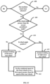
- FIG. 1 is a flowchart depicting the process of selecting a mode of operation for an electric vehicle.
- data related to the vehicle such as, but not limited to, dimensions of the vehicle, turning radius of the vehicle (with/without braking), implement(s) currently connected to the vehicle, and so on, are pre-configured by an operator and/or authorized person.
- the data related to the field where the vehicle is currently operating, is collected.
- the data can be collected using a camera (mounted on the vehicle), processing media from the camera, and estimating the field size and location of significant areas (such as the headlands) using the processed media.
- the user/operator can provide the data related to the field.
- a user interface can be used to display the current location of the vehicle to the user, and the user can mark out the location and size of the field, headland area on the user interface.
- the soil condition is determined. Examples of the soil condition can be, but not limited to, hard, soft, medium, and so on.
- a draft sensor can be mounted in a suitable location on the vehicle (such as the 3-point linkage). The draft sensor can sense the soil in the field and determine the condition of the soil based on draft values.
- a mode for operation of the vehicle is automatically selected, based on the determined soil conditions. In an embodiment herein, the mode can be selected manually.
- the mode can be selected automatically, based on additional parameters, such as, current turning angle, farm size, soil conditions, current wheel angle, brake pedal status (actuated/not actuated), vehicle speed, and so on.
- step 104 the vehicle is operated using the selected mode.
- the various actions in method 100 may be performed in the order presented, in a different order or simultaneously. Further, in some embodiments, some actions listed in FIG. 1 may be omitted.
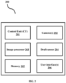
- FIG. 2 depicts an architecture for selecting a mode of operation of the vehicle, when the vehicle is taking a headland turn.
- the system (200) comprises a control unit (CU) (201), one or more cameras (202), an image processor (203), a draft sensor (204), a memory (205), and one or more user interfaces (206).
- CU control unit
- 202 one or more cameras
- 203 image processor
- 204 draft sensor
- 205 a memory
- user interfaces 206
- the one or more user interfaces (206) can enable the user and/or operator to interact with the vehicle, and perform one or more operation (such as selecting/de-selecting the mode of operation of the vehicle, providing data related to the farm/field, where the vehicle is operating, and so on).
- the user interface (206) can also enable the user to view data such as the currently selected mode, the speed of the vehicle, location of the user, and so on.
- Examples of the user interface (206) can be, but not limited to, a display, one or more switches, one or more lights, an instrument console, a panel, and so on.
- the user interface (206) can also comprise a device belonging to the user, such as, a mobile device, a phone, a tablet, a wearable device, a computer, an Internet of Things (IoT) device, and so on.
- IoT Internet of Things
- One or more cameras (202) can collect information of the location of the field.
- the information can be at least one of images, videos, and so on.
- the cameras can be mounted on the vehicle, in such locations so as to get a clear field of view of the location of the vehicle.
- the information can be provided to the image processor (203), wherein the image processor (203) can process the information. Examples of the processing done can be levelling, cropping out unnecessary portions (such as the sky), noise reduction, and so on.
- the processed information can be provided to the CU (201).
- the CU (201) can analyze the information to determine data related to the field, such as field size, shape, headland location, and so on.
- the draft sensor (204) can determine the current soil condition.
- the draft sensor can be mounted in a suitable location on the vehicle (such as the 3-point linkage).
- the draft sensor (204) can sense the soil in the field and determine the condition of the soil based on the sensed draft values.
- the draft sensor (204) can provide the sensed draft values to the CU (201).
- the CU (201) based on the information received from the image processor (203) and the draft sensor (204), and additional data (such as the soil draft value, current speed of the vehicle, current turning angle, current wheel angle, brake pedal status, implement width and so on), can determine the mode of operation of the vehicle.
- the mode of operation can be one of a low mode, a medium mode, and a high/aggressive mode.
- the CU (201) can adjust the speed of the driving motors of the respective wheels and/or adjust the brakes of the vehicle, so as to enable the vehicle to make headland turns with minimal radius.
- the user can manually select the mode of operation using the user interface (206). Based on the selected mode, the CU (201) can adjust the speed of the driving motors of the respective wheels and/or adjust the brakes of the vehicle, so as to enable the vehicle to make headland turns with minimal radius.
- the memory (205) stores at least one of, the vehicle data, the field data, camera feed, sensed soil conditions, currently selected mode, current operating conditions of the vehicle (such as speed, brake status, steering wheel angle, and so on), current implement(s) being used, and so on.
- Examples of the memory (205) may be, but are not limited to, NAND, embedded Multimedia Card (eMMC), Secure Digital (SD) cards, Universal Serial Bus (USB), Serial Advanced Technology Attachment (SATA), Solid-State Drive (SSD), and so on.
- the memory (205) may include one or more computer-readable storage media.
- the memory (205) may include one or more non-volatile storage elements.
- non-volatile storage elements may include Read Only Memory (ROM), magnetic hard discs, optical discs, floppy discs, flash memories, or forms of Electrically PROgrammable Memories (EPROM) or Electrically Erasable and PROgrammable Memories (EEPROM).
- ROM Read Only Memory
- EPROM Electrically PROgrammable Memories
- EEPROM Electrically Erasable and PROgrammable Memories
- the memory (205) may, in some examples, be considered a non-transitory storage medium.
- the term “non-transitory” may indicate that the storage medium is not embodied in a carrier wave or a propagated signal. However, the term “non-transitory” should not be interpreted to mean that the memory is non-movable.
- a non-transitory storage medium may store data that may, over time, change (e.g., in Random Access Memory (RAM) or cache).
- RAM Random Access Memory
- the vehicle can comprise of additional sensors/modules such as GPS sensors, wheel speed sensor, brake actuators, brake pedal latch sensors, and so on (not shown), which provide data and information to the CU (201) and/or to the user/operator.
- sensors/modules such as GPS sensors, wheel speed sensor, brake actuators, brake pedal latch sensors, and so on (not shown), which provide data and information to the CU (201) and/or to the user/operator.
- the soil draft value is greater than 1000kg. Accordingly, the CU (201) selects the low mode and displays instructions to the user. In an example, the CU (201) can inform the user to skip 2 rows and then attempt the headland turn. The CU (201) can activate the low mode, when the steering wheel angle is greater than a first pre-defined angle (for example, 30 degrees).
- a first pre-defined angle for example, 30 degrees.
- headland turn is complicated; i.e., with respect to field size & vehicle dimension, headland turn is equal to the required width with respect to vehicle dimensions.
- the soil draft value is greater than 500kg. Accordingly, the CU (201) selects the medium mode and displays instructions to the user. In an example, the CU (201) can inform the user to skip 1 row and then attempt the headland turn. The CU (201) can activate the medium mode, when the steering wheel angle is greater than a second pre-defined angle (for example, 25 degrees).
- a second pre-defined angle for example, 25 degrees.
- the soil draft value is from 0 to 500kg. Accordingly, the CU (201) chooses the high/aggressive mode and displays instructions to the user. In an example, the CU (201) can inform the user to skip 1 row and then attempt the headland turn. The CU (201) can activate the high/aggressive mode, when the steering wheel angle is greater than a third pre-defined angle (for example, 20 degrees).
- a third pre-defined angle for example, 20 degrees.
- FIG. 3 depicts an architecture wherein a single traction motor is used for the front wheels and a single traction motor is used for the rear wheels. Both the front and rear axles of the vehicle have differential to enable the inner wheel to slip during a turning operation. Based on factors such as whether the mode has been selected manually, turning angle, soil conditions, vehicle speed, wheel angle (from the front right side), brake pedal latch status, inputs from the rear traction motor (TR), the GPS sensor and the camera, the CU (201) can actuate the inner wheel brake actuator and/or speed of the front wheels (based on the mode, that has been currently selected).
- the CU (201) activates one of the brake actuators (either the left side or the right side), depending on which side the vehicle is turning. Depending on the turning side, the CU (201) can apply brakes to the respective inner rear wheel.
- the CU (201) can determine that the vehicle is making a right turn, by detecting that the wheel angle is positive.
- the CU (201) can determine that the vehicle is making a left turn, by detecting that the wheel angle is negative.
- the CU (201) activates one of the brake actuators (either the left side or the right side), depending on which side the vehicle is turning.
- the CU (201) can determine that the vehicle is making a right turn, by detecting that the wheel angle is positive.
- the CU (201) can determine that the vehicle is making a left turn, by detecting that the wheel angle is negative.
- the CU (201) can apply brakes to the respective inner rear wheel.
- the CU (201) can further increase the rotational speed of the front wheels to a first speed greater than the rotational speed of the rear wheels. In an example, the CU (201) can further increase the rotational speed of the front wheels to be 1.2 times faster, as compared to the rotational speed of the rear wheels.
- the CU (201) activates inner wheel brake actuators (either the left side or the right side), depending on which side the vehicle is turning.
- the CU (201) can determine that the vehicle is making a right turn, by detecting that the wheel angle is positive.
- the CU (201) can determine that the vehicle is making a left turn, by detecting that the wheel angle is negative.
- the CU (201) can apply brakes to the respective inner rear wheel.
- the CU (201) can further increase the rotational speed of the front wheels to be a second speed greater than the rotational speed of the rear wheels. In an example, the CU (201) can further increase the rotational speed of the front wheels to be 1.6 times faster, as compared to the rotational speed of the rear wheels.
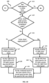
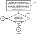
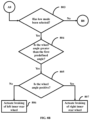
- FIGs. 4A , 4B , 4C and 4D are flowcharts depicting the process of using a single traction motor for the front wheels and a single traction motor for the rear wheels respectively.
- the CU (201) reads data, such as, but not limited to, whether the mode is to be selected manually, data from the wheel angle sensor, data from the front speed sensor, data from the brake latch switch, data from the draft sensor, vehicle data, field data, and so on.
- the CU (201) checks if the mode has to be selected automatically, the brake latch switch is OFF, and the speed of the vehicle is less than a pre-defined speed threshold.
- the CU (201) checks if the low mode has been selected. In the low mode has been selected, in step 404, the CU (201) checks if the wheel angle is greater than the first predefined angle. If the wheel angle is greater than the first predefined angle, in step 405, the CU (201) checks if the wheel angle is positive. If the wheel angle is not positive, in step 406, the CU (201) actuates braking of the left inner rear wheel. If the wheel angle is positive, in step 407, the CU (201) actuates braking of the right inner rear wheel.
- the CU (201) checks if the medium mode has been selected. If the medium mode has been selected, in step 409, the CU (201) checks if the wheel angle is greater than the second predefined angle. If the wheel angle is greater than the second predefined angle, in step 410, the CU (201) checks if the wheel angle is positive. If the wheel angle is not positive, in step 411, the CU (201) actuates braking of the left inner rear wheel. If the wheel angle is positive in step 412, the CU (201) actuates braking of the right inner rear wheel. In step 413, the CU (201) sets the rotational speed of the front wheels to be a first speed greater than the speed of the rear wheels. In an example, the CU (201) can further increase the rotational speed of the front wheels to be 1.2 times faster, as compared to the rear wheels.
- the CU (201) checks if the high/aggressive mode has been selected. If the high/aggressive mode has been selected, in step 415, the CU (201) checks if the wheel angle is greater than the third predefined angle. If the wheel angle is greater than the third predefined angle, in step 416, the CU (201) checks if the wheel angle is positive. If the wheel angle is not positive, in step 417, the CU (201) actuates braking of the left inner rear wheel. If the wheel angle is positive, in step 418, the CU (201) actuates braking of the right inner rear wheel.
- the CU (201) sets the rotational speed of the front wheels to be a second speed greater than the speed of the rear wheels.
- the CU (201) can further increase the rotational speed of the front wheels to be 1.6 times faster, as compared to the rear wheels.
- the various actions in method 400 may be performed in the order presented, in a different order or simultaneously. Further, in some embodiments, some actions listed in FIGs. 4A , 4B , 4C and 4D may be omitted.
- FIG. 5 depicts an architecture wherein an independent traction motor is used for each of the front wheels and a single traction motor is used for the rear wheels. Only the rear axles of the vehicle have a differential to enable the inner wheel to slip during a turning operation. Based on a plurality of factors (such as whether the mode has been selected manually, turning angle, soil conditions, vehicle speed, wheel angle, brake pedal latch status, the GPS sensor, and the camera), the CU (201) can actuate the inner wheel brake actuator and/or speed of the front wheels (based on the mode, that has been currently selected).
- the CU (201) activates one of the brake actuators (either the left side or the right side), depending on which side the vehicle is turning. Depending on the turning side, the CU (201) can apply brakes to the respective inner rear wheel.
- the CU (201) can determine that the vehicle is making a right turn, by detecting that the wheel angle is positive.
- the CU (201) can determine that the vehicle is making a left turn, by detecting that the wheel angle is negative.
- the CU (201) activates one of the brake actuators (either the left side or the right side), depending on which side the vehicle is turning.
- the CU (201) can determine that the vehicle is making a right turn, by detecting that the wheel angle is positive.
- the CU (201) can determine that the vehicle is making a left turn, by detecting that the wheel angle is negative.
- the CU (201) can apply brakes to the respective inner rear wheel.
- the CU (201) can further increase the rotational speed of the front wheels to be a first speed greater than the rotational speed of the rear wheels.
- the CU (201) can further increase the rotational speed of the front wheels to be 1.2 times faster, as compared to the rear wheels.
- the CU (201) can further rotate the outer front wheel faster than the inner front wheel.
- the CU (201) activates one of the brake actuators (either the left side or the right side), depending on which side the vehicle is turning.
- the CU (201) can determine that the vehicle is making a right turn, by detecting that the wheel angle is positive.
- the CU (201) can determine that the vehicle is making a left turn, by detecting that the wheel angle is negative.
- the CU (201) can apply brakes to the respective inner rear wheel.
- the CU (201) can further increase the rotational speed of the front wheels to be a second speed greater than the rotational speed of the rear wheels.
- the CU (201) can further increase the rotational speed of the front wheels to be 1.6 times faster, as compared to the rotational speed of the rear wheels.
- the CU (201) can further increase the rotational speed of the front outer wheel to be a third speed greater than the speed of the front inner wheels.
- the CU (201) can further increase the rotational speed of the front outer wheels to be 1.2 times faster, as compared to the front inner wheels.
- FIGs. 6A , 6B , 6C and 6D are flowcharts depicting the process of using an independent traction motor for each of the front wheels and a single traction motor for the rear wheels.
- the CU (201) reads data, such as, but not limited to, whether the mode is to be selected manually, data from the wheel angle sensor, data from the front speed sensor, data from the rear speed sensor, data from the brake latch switch, data from the draft sensor, vehicle data, field data, and so on.
- the CU (201) checks if the mode has to be selected automatically, the brake latch switch is OFF, and the vehicle speed is lower than the predefined speed threshold.
- the CU (201) checks if the low mode has been selected. If the low mode has been selected, in step 604, the CU (201) checks if the wheel angle is greater than the first predefined angle. If the wheel angle is greater than the first predefined angle, in step 605, the CU (201) checks if the wheel angle is positive. If the wheel angle is not positive, in step 606, the CU (201) actuates braking of the left inner rear wheel. If the wheel angle is positive, in step 607, the CU (201) actuates braking of the right inner rear wheel.
- the CU (201) checks if the medium mode has been selected. If the medium mode has been selected, in step 609, the CU (201) checks if the wheel angle is greater than the second predefined angle. If the wheel angle is greater than the second predefined angle, in step 610, the CU (201) checks if the wheel angle is positive. If the wheel angle is not positive, in step 611, the CU (201) actuates braking of the left inner rear wheel. If the wheel angle is positive, in step 612, the CU (201) actuates braking of the right inner rear wheel. In step 613, the CU (201) sets the rotational speed of the front wheels to be a first speed greater than the speed of the rear wheels. In an example, the CU (201) can further increase the rotational speed of the front wheels to be 1.2 times faster, as compared to the rotational speed of the rear wheels.
- the CU (201) checks if the high/aggressive mode has been selected. If the high mode has been selected, in step 615, the CU (201) checks if the wheel angle is greater than the third predefined angle. If the wheel angle is greater than the third predefined angle, in step 616, the CU (201) checks if the wheel angle is positive. If the wheel angle is not positive, in step 617, the CU (201) actuates braking of the left inner rear wheel. In step 618, the CU (201) sets the right front wheel speed to be YX times greater than the left front wheel speed.
- the CU (201) sets the right front wheel speed to be 1.2 times (i.e., the value of YX is 1.2) greater than the left front wheel speed. If the wheel angle is positive, in step 619, the CU (201) actuates braking of the right inner rear wheel. In step 620, the CU 101 sets the left front wheel speed to be YX times greater than the right front wheel speed. In step 621, the CU (201) sets the rotational speed of the front wheels to be a second speed greater than the speed of the rear wheels. In an example, the CU (201) can further increase the rotational speed of the front wheels to be 1.6 times faster, as compared to the rotational speed of the rear wheels.
- the various actions in method 600 may be performed in the order presented, in a different order or simultaneously. Further, in some embodiments, some actions listed in FIGs. 6A , 6B , 6C and 6D may be omitted.
- FIG. 7 depicts an architecture wherein independent traction motors are used for each of the front wheels and are used for each of the rear wheels.
- the vehicle is equipped with independent traction motor for each of the front wheels and the rear wheels.
- the CU (201) can actuate the inner wheel brake actuator and/or speed of the front wheels (based on the mode, that has been currently selected).
- the CU (201) can reduce the speed of the inner rear wheel motor to near zero.
- the CU (201) can reduce the speed of the inner rear wheel motor to near zero.
- the CU (201) can further increase the rotational speed of the front wheels to a first speed greater than the speed of the rear wheels.
- the CU (201) can further increase the rotational speed of the front wheels to be 1.2 times faster, as compared to the rotational speed of the rear wheels.
- the CU (201) can further rotate the outer front wheel faster than the inner front wheel.
- the CU (201) can reduce the speed of the inner rear wheel motor to near zero.
- the CU (201) can further increase the rotational speed of the front wheels to a second speed greater than the speed of the rear wheels.
- the CU (201) can further increase the rotational speed of the front wheels to be 1.6 times faster, as compared to the rotational speed of the rear wheels.
- the CU (201) can further increase the rotational speed of the front outer wheel to be a third speed greater than the speed of the front inner wheels.
- the CU (201) can further increase the rotational speed of the front outer wheels to be 1.2 times faster, as compared to the front inner wheels.
- FIGs. 8A , 8B , 8C and 8D are flowcharts depicting the process of using independent traction motors for each of the front wheels and for each of the rear wheels.
- the CU (201) reads data, such as, but not limited to, whether the mode is to be selected manually, data from the wheel angle sensor, data from the front speed sensor, data from the rear speed sensor, data from the brake latch switch, data from the draft sensor, vehicle data, field data, and so on.
- the CU (201) checks if the mode has to be selected automatically, the brake latch switch is OFF, and the vehicle speed is less than the predefined speed threshold.
- the CU (201) checks if the low mode has been selected. If the low mode has been selected, in step 804, the CU (201) checks if the wheel angle is greater than the first predefined angle. If the wheel angle is greater than the first predefined angle, in step 805, the CU (201) checks if the wheel angle is positive. If the wheel angle is not positive, in step 806, the CU (201) actuates braking of the left inner rear wheel. If the wheel angle is positive and the speed of the vehicle is less than the pre-defined speed threshold, in step 807, the CU (201) actuates the braking of the right inner rear wheel.
- the CU (201) checks if the medium mode has been selected. If the medium mode has been selected, in step 809, the CU (201) checks if the wheel angle is greater than the second predefined angle. If the wheel angle is greater than the second predefined angle, in step 810, the CU (201) checks if the wheel angle is positive. If the wheel angle is not positive, in step 811, the CU (201) reduces the speed of the inner left rear wheel to near zero. If the wheel angle is positive, in step 812, the CU (201) . In step 813, the CU (201) sets the rotational speed of the front wheels to be a first speed greater than the speed of the rear wheels. In an example, the CU (201) can further increase the rotational speed of the front wheels to be 1.2 times faster, as compared to the rear wheels.
- step 814 the CU (201) checks if the high/aggressive mode has been selected. If the high/aggressive mode has been selected, in step 815, the CU (201) checks if the wheel angle is greater than the third predefined angle. If the wheel angle is greater than the third predefined angle, in step 816, the wheel angle is positive. If the wheel angle is not positive, in step 817, the CU (201) actuates braking of the left inner rear wheel. In step 818, the CU (201) sets the speed of the right front wheel to be XYZ times greater than the speed of the left front wheel. If the wheel angle is positive, in step 819, the CU (201) actuates braking of the right inner rear wheel.
- step 820 the CU (201) sets the speed of the left front wheel to be XYZ times greater than the speed of the right front wheel.
- step 821 the CU (201) sets the rotational speed of the front wheels to be a second speed greater than the speed of the rear wheels.
- the CU (201) can further increase the rotational speed of the front wheels to be 1.6 times faster, as compared to the rotational speed of the rear wheels.
- method 800 may be performed in the order presented, in a different order or simultaneously. Further, in some embodiments, some actions listed in FIGs. 8A , 8B , 8C and 8D may be omitted.
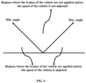
- FIG. 9 is an example diagram depicting the angular range over which the brakes and/or the speed of the vehicle may be automatically adjusted.
- the CU (201) can check if the angle of the wheel is greater than the minimum angle (min_angle) or less than the maximum angle (max_angle), and the CU (201) can apply the brakes of the vehicle and/or adjust the speed of the vehicle (if the aforementioned angular conditions are met).
- the embodiments disclosed herein can be implemented through at least one software program running on at least one hardware device and performing network management functions to control the network elements.
- the elements include blocks which can be at least one of a hardware device, or a combination of hardware device and software module.
- the embodiment disclosed herein describes methods and systems for optimizing the productivity and improving the stability of electric vehicles by automatically speeding up front wheels and outer wheels of the vehicle, during operations. Therefore, it is understood that the scope of the protection is extended to such a program and in addition to a computer readable means having a message therein, such computer readable storage means contain program code means for implementation of one or more steps of the method, when the program runs on a server or mobile device or any suitable programmable device.
- the method is implemented in at least one embodiment through or together with a software program written in e.g., Very high speed integrated circuit Hardware Description Language (VHDL) another programming language, or implemented by one or more VHDL or several software modules being executed on at least one hardware device.
- VHDL Very high speed integrated circuit Hardware Description Language
- the hardware device can be any kind of portable device that can be programmed.
- the device may also include means which could be e.g., hardware means like e.g., an ASIC, or a combination of hardware and software means, e.g., an ASIC and an FPGA, or at least one microprocessor and at least one memory with software modules located therein.
- the method embodiments described herein could be implemented partly in hardware and partly in software.
- the invention may be implemented on different hardware devices, e.g., using a plurality of CPUs.
Landscapes
- Engineering & Computer Science (AREA)
- Mechanical Engineering (AREA)
- Transportation (AREA)
- Life Sciences & Earth Sciences (AREA)
- Power Engineering (AREA)
- Soil Sciences (AREA)
- Environmental Sciences (AREA)
- Automation & Control Theory (AREA)
- Physics & Mathematics (AREA)
- Mathematical Physics (AREA)
- Regulating Braking Force (AREA)
Applications Claiming Priority (1)
| Application Number | Priority Date | Filing Date | Title |
|---|---|---|---|
| IN202341064356 | 2023-09-25 |
Publications (1)
| Publication Number | Publication Date |
|---|---|
| EP4527701A1 true EP4527701A1 (fr) | 2025-03-26 |
Family
ID=90473244
Family Applications (1)
| Application Number | Title | Priority Date | Filing Date |
|---|---|---|---|
| EP24165272.6A Pending EP4527701A1 (fr) | 2023-09-25 | 2024-03-21 | Procédés et systèmes d'assistance d'un véhicule électrique dans des opérations de bouture |
Country Status (3)
| Country | Link |
|---|---|
| US (1) | US20250098561A1 (fr) |
| EP (1) | EP4527701A1 (fr) |
| CA (1) | CA3242645A1 (fr) |
Citations (3)
| Publication number | Priority date | Publication date | Assignee | Title |
|---|---|---|---|---|
| EP2110295A2 (fr) * | 2008-04-18 | 2009-10-21 | Kanzaki Kokyukoki Mfg. Co., Ltd. | Véhicule électrique pour travailler le sol |
| WO2021005406A1 (fr) * | 2019-07-08 | 2021-01-14 | Mahindra And Mahindra Limited | Système de rotation de tournière pour une machine agricole |
| US20210271255A1 (en) * | 2020-02-28 | 2021-09-02 | Cnh Industrial America Llc | System and method for executing multi-mode turns with a work vehicle |
-
2024
- 2024-03-21 EP EP24165272.6A patent/EP4527701A1/fr active Pending
- 2024-03-21 US US18/612,322 patent/US20250098561A1/en active Pending
- 2024-06-20 CA CA3242645A patent/CA3242645A1/en active Pending
Patent Citations (3)
| Publication number | Priority date | Publication date | Assignee | Title |
|---|---|---|---|---|
| EP2110295A2 (fr) * | 2008-04-18 | 2009-10-21 | Kanzaki Kokyukoki Mfg. Co., Ltd. | Véhicule électrique pour travailler le sol |
| WO2021005406A1 (fr) * | 2019-07-08 | 2021-01-14 | Mahindra And Mahindra Limited | Système de rotation de tournière pour une machine agricole |
| US20210271255A1 (en) * | 2020-02-28 | 2021-09-02 | Cnh Industrial America Llc | System and method for executing multi-mode turns with a work vehicle |
Also Published As
| Publication number | Publication date |
|---|---|
| US20250098561A1 (en) | 2025-03-27 |
| CA3242645A1 (en) | 2025-06-17 |
Similar Documents
| Publication | Publication Date | Title |
|---|---|---|
| US11647686B2 (en) | System and method for communicating the presence of proximate objects in a working area | |
| JP7838041B2 (ja) | 自動走行システム、自動走行方法、及び自動走行プログラム | |
| US20230415779A1 (en) | Assistance method of safe driving and electronic device | |
| JP2016097896A (ja) | 画像表示制御装置 | |
| DE102016114288A1 (de) | Einparkhilfevorrichtung und verfahren zum steuern derselben | |
| KR102202522B1 (ko) | 차량에 대한 조향각 제어 신호를 제공하기 위한 장치, 방법 및 컴퓨터 프로그램 | |
| US20220379956A1 (en) | System and Method for Controlling Steering Torque of a Steering System of a Vehicle | |
| EP3115930A1 (fr) | Appareil de diagnostic de défaillance | |
| DE102019208374A1 (de) | Gerät für automatisches parken eines fahrzeugs in einer persönlichen garage, system, welches dasselbe beinhaltet, und verfahren hierfür | |
| CN112009462A (zh) | 一种前向自动泊车方法及装置 | |
| CN106004277A (zh) | 拖曳杆控制系统 | |
| CN111918803A (zh) | 车辆的驾驶辅助控制装置、车辆的驾驶辅助系统和车辆的驾驶辅助控制方法 | |
| US20250091573A1 (en) | Validating a travel corridor for lateral guidance of a motor vehicle | |
| CN105799591A (zh) | 路面图像的显示装置 | |
| EP4527701A1 (fr) | Procédés et systèmes d'assistance d'un véhicule électrique dans des opérations de bouture | |
| CN112417976B (zh) | 一种路面检测识别方法、装置、智能终端及存储介质 | |
| JP2023115753A (ja) | 遠隔操作システム、遠隔操作制御方法、及び遠隔オペレータ端末 | |
| US20230419682A1 (en) | Method for managing driving and electronic device | |
| CN114407783B (zh) | 一种车辆后视镜的随动控制方法、系统、装置 | |
| CN114644014A (zh) | 一种基于车道线的智能驾驶方法及相关设备 | |
| CN113353084B (zh) | 用于车辆控制的方法及设备 | |
| AU2018375585B2 (en) | Operator assistance vision system | |
| WO2024143437A1 (fr) | Appareil de commande à distance et système de manipulation à distance | |
| US12263857B2 (en) | Method for assisting safer driving and electronic device | |
| US11047673B2 (en) | Method, device, apparatus and storage medium for detecting a height of an obstacle |
Legal Events
| Date | Code | Title | Description |
|---|---|---|---|
| PUAI | Public reference made under article 153(3) epc to a published international application that has entered the european phase |
Free format text: ORIGINAL CODE: 0009012 |
|
| STAA | Information on the status of an ep patent application or granted ep patent |
Free format text: STATUS: THE APPLICATION HAS BEEN PUBLISHED |
|
| AK | Designated contracting states |
Kind code of ref document: A1 Designated state(s): AL AT BE BG CH CY CZ DE DK EE ES FI FR GB GR HR HU IE IS IT LI LT LU LV MC ME MK MT NL NO PL PT RO RS SE SI SK SM TR |
|
| STAA | Information on the status of an ep patent application or granted ep patent |
Free format text: STATUS: REQUEST FOR EXAMINATION WAS MADE |
|
| 17P | Request for examination filed |
Effective date: 20250926 |