EP4527729A1 - Verankerungsverfahren und -vorrichtung - Google Patents
Verankerungsverfahren und -vorrichtung Download PDFInfo
- Publication number
- EP4527729A1 EP4527729A1 EP23250003.3A EP23250003A EP4527729A1 EP 4527729 A1 EP4527729 A1 EP 4527729A1 EP 23250003 A EP23250003 A EP 23250003A EP 4527729 A1 EP4527729 A1 EP 4527729A1
- Authority
- EP
- European Patent Office
- Prior art keywords
- components
- group
- tension
- rope
- winding
- Prior art date
- Legal status (The legal status is an assumption and is not a legal conclusion. Google has not performed a legal analysis and makes no representation as to the accuracy of the status listed.)
- Withdrawn
Links
Images



Classifications
-
- B—PERFORMING OPERATIONS; TRANSPORTING
- B63—SHIPS OR OTHER WATERBORNE VESSELS; RELATED EQUIPMENT
- B63B—SHIPS OR OTHER WATERBORNE VESSELS; EQUIPMENT FOR SHIPPING
- B63B21/00—Tying-up; Shifting, towing, or pushing equipment; Anchoring
- B63B21/50—Anchoring arrangements or methods for special vessels, e.g. for floating drilling platforms or dredgers
- B63B21/507—Anchoring arrangements or methods for special vessels, e.g. for floating drilling platforms or dredgers with mooring turrets
- B63B21/508—Anchoring arrangements or methods for special vessels, e.g. for floating drilling platforms or dredgers with mooring turrets connected to submerged buoy
-
- B—PERFORMING OPERATIONS; TRANSPORTING
- B63—SHIPS OR OTHER WATERBORNE VESSELS; RELATED EQUIPMENT
- B63B—SHIPS OR OTHER WATERBORNE VESSELS; EQUIPMENT FOR SHIPPING
- B63B21/00—Tying-up; Shifting, towing, or pushing equipment; Anchoring
- B63B21/16—Tying-up; Shifting, towing, or pushing equipment; Anchoring using winches
-
- B—PERFORMING OPERATIONS; TRANSPORTING
- B63—SHIPS OR OTHER WATERBORNE VESSELS; RELATED EQUIPMENT
- B63B—SHIPS OR OTHER WATERBORNE VESSELS; EQUIPMENT FOR SHIPPING
- B63B21/00—Tying-up; Shifting, towing, or pushing equipment; Anchoring
- B63B21/50—Anchoring arrangements or methods for special vessels, e.g. for floating drilling platforms or dredgers
-
- B—PERFORMING OPERATIONS; TRANSPORTING
- B63—SHIPS OR OTHER WATERBORNE VESSELS; RELATED EQUIPMENT
- B63B—SHIPS OR OTHER WATERBORNE VESSELS; EQUIPMENT FOR SHIPPING
- B63B22/00—Buoys
- B63B22/02—Buoys specially adapted for mooring a vessel
Definitions
- the present invention relates to a method of adjusting a length of rope for mooring a floating structure and a mooring apparatus for mooring the same.
- Floating structures are commonplace in the energy industry, for example they are used for well drilling, hydrocarbon production, oil platforms, floating solar platforms, floating wind platforms, data gathering etc. These structures are typically located a significant distance from the coast and there is a need to hold them in a relatively fixed position.
- Synthetic ropes have numerous benefits over chains, for instance a synthetic rope is on average approximately 10% of the weight of a chain of similar length making them easier to install. Synthetic ropes are also cheaper than chains of a similar length and are better adapted to mooring floating wind turbines.
- Typical mooring lines may be up to 1000m in length and a change by up to 10% may be expected. This can result in a significant loss of tension in the mooring line.
- chains or additional ropes are connected to the main synthetic mooring rope to adjust the length of the overall rope.
- This conventional system will be discussed in more detail below, but typically a first chain is connected to an end of the synthetic rope and passed through a ratchet device. A second chain connects the ratchet to the floating structure.
- a specialised vessel is used to retrieve the other end of the first chain which is then pulled through the ratchet to tension the synthetic rope. The length of the first chain between the ratchet and the end of the synthetic mooring line is therefore reduced to account for the elongation of the synthetic rope.
- This conventional system requires the use of a separate length of chain which adds weight and complexity to the mooring apparatus. Moreover, chains can corrode over time meaning that they would have to be replaced at regular intervals. In addition, this adjustment system requires a specialised vessel to perform the tensioning which has numerous drawbacks such as added costs. Moreover, the vessel must be available for the operation and the weather conditions must be appropriate. Another drawback is that the length by which the mooring line can be adjusted is limited by the length of the first chain.
- a method of adjusting a length of a rope comprising a plurality of parallel load bearing components for mooring of a floating structure, the method comprising: isolating individual components or groups of components from the plurality of parallel load bearing components; guiding each component or group of components around a respective winding spool; and rotating at least one of the winding spools to pull the respective component or group of components.
- the effective length of the rope can be adjusted, while the position of an anchor (i.e. the winding spools) remains fixed relative to the floating structure or bed of the body of water. Therefore, during the length adjustment process, the distance between the two end points of the rope remains the same. This differs from conventional systems whereby a section of the chain is removed, but the distance between the two end points of the synthetic rope has increased.
- the above aspect effectively results in an adjustment of the anchor location relative to the rope. In previous systems, and in prior synthetic rope based systems, the effective length of the synthetic rope is not adjusted, rather the anchor point is moved to accommodate the change in length of the synthetic rope.
- the method of adjusting the length of rope can therefore be used to make large adjustments to the rope as the anchor point remains in a fixed point relative to the platform.
- the anchor point is moved there is a limit on how much the length can be adjusted by.
- each of the parallel components and connecting them to respective winding spools either individually or in groups
- the force required by each winding spool to pull the component or group of components may be significantly reduced compared to the force that would be required to pull the entire rope as one unit.
- the tension required in each component or group of components is less than the tension required in the overall rope. As the tension required is lower, this reduces the load on the winding spool compared to the load that would be present if the rope as a whole was to be tensioned. If a lower tensioning is required, additional components or groups of components may be provided in the rope.
- the method therefore means that the required tension can be applied to the rope without the need for large winches or additional components or specialised vessels. This has the effect of simplifying and reducing the cost of the length adjustment process as the separate chain is no longer required. This also negates the need for separate large scale components such as complicated winching systems or additional vessels.
- the adjustment can be carried out by individuals located on the floating structure, or remotely. In both cases, the adjustment may be manual or automatic.
- a rope comprising a plurality of parallel load bearing components means that redundancies are in place. In the event of one of the parallel load bearing components failing, the other of the plurality of load bearing components may take up the excess load.
- the parallel load bearing components may be formed of any material capable of withstanding anchoring and/or winching.
- the parallel load bearing components may be formed of synthetic materials such as nylon, polyester, High Modulus Polyethylene (HMPE), Aromatic Polyamide (Aramid) or polyoxymethylene (POM).
- the diameter of the parallel load bearing components may be in a range of between 10mm to 80mm.
- the diameter of the overall rope may be in the range of 100mm to 300mm.
- the load in the rope may be the tension caused by the rope being fixed relative to a sea bed at one end, and fixed relative to a floating structure. Over time, the rope may elongate which will reduce the load and therefore the tension in the rope and hence the load and tension in each parallel load bearing component. By adjusting the length, the tension in the rope is also adjusted. Length adjustment may therefore be referred to herein as tensioning.
- Each parallel load bearing component may be formed of a plurality of braided fibres.
- each parallel load bearing component may be formed of a plurality of twisted or laid fibres.
- Each parallel load bearing component may be grouped together and covered by rope cover along the length of the rope. Moreover, each parallel load bearing component may comprise a component cover. The rope cover may be fixed at both the first and second end of the rope such that it may elongate as the rope elongates.
- the rope cover may not be directly connected to each parallel load bearing component.
- the rope cover may be able to move relative to each parallel load bearing component. This can allow for changes in length of each parallel load bearing component.
- the method may comprise rotating at least one of the winding spools to pull the respective component or group of components. This can apply tension to the component or group of components. This in turn may adjust the length of the rope and apply tension to the rope.
- Each winding spool may be rotated individually to pull each respective component or group of components in sequence. In this instance, the rotation may be incremental to avoid overstraining.
- Each winding spool may rotate in sequence to pull the respective component or group of components by a portion of the overall length adjustment required. This process may then be repeated until the amount of the component or group of components pulled by the winding spool is equivalent to the overall length adjustment required.
- one winding spool may be rotated to pull the respective components or group of components by a portion of the overall length adjustment that is required.
- the rotation of the winding spool may apply a portion of the tension to the component or groups of components.
- This process may then be carried out for the other winding spools and components or groups of components.
- another, different, winding spool may be rotated to pull the respective components or group of components by the same portion of the overall length adjustment that is required.
- each winding spool is then rotated in sequence again to pull the respective component or group of components by a second portion of the overall length adjustment required.
- the second portion may be the same as the portion of the previous step. This process may be continued until each respective component or group of components has been pulled by an amount equal to the overall length adjustment required.
- the above process prevents one or more of the components or groups of components from becoming overstrained. Moreover, by rotating each winding spool individually, the length adjustment can be more closely monitored and it can be carried out by an individual if necessary who may not be able to rotate all the winding spools simultaneously.
- the method may thus comprise rotating each winding spool in sequence.
- each winding spool may be rotated simultaneously to pull each respective component or group of components simultaneously.
- the strain in each of the plurality of components can be kept uniform and balanced within the rope. This means that each winding spool may be rotated continuously to pull the respective component or groups of components which results in a faster and more efficient length adjustment process.
- the at least one winding spool may be rotated to pull the respective component or group of components by a deadweight so that tension is applied automatically in the event of a reduction in tension in the respective component or group of components.
- the deadweight may hang in a vertically downward direction.
- the deadweight may be sized to provide sufficient tension to the respective component or group of components to generate a holding tension via a capstan effect.
- the at least one winding spool may be rotated to pull the respective component or group of components by a buoyant body so that tension may be applied automatically in the event of a reduction in tension in the respective component or group of components.
- the buoyant body may be located in a vertically upward direction relative to the at least one winding spool.
- the buoyant body may be sized to provide sufficient tension in the respective component or group of components to generate a holding tension via a capstan effect.
- the deadweight or buoyant body may be attached directly or indirectly to the respective component or group of components wound around the at least one winding spool.
- the component or groups of components may be wound about the winding spool and then extend away from the winding spool to a end point.
- the end point of the component or group of components may be located directly below or above the winding spool.
- the deadweight or buoyant body may be directly or indirectly connected to the end point.
- a direct connection in this instance means that the deadweight may comprise an attachment point which the end point is connected to.
- the deadweight or buoyant body may be attached to a separate member which may then be connected to the end point.
- the end point of the component or group of components may be fixed to the winding spool.
- the deadweight or buoyant body may be connected to the winding spool.
- the at least one winding spool may be rotated to apply tension to the respective component or group of components using a mechanical winding system which applies a torque to the winding spool.
- the mechanical winding system may be used instead of the deadweight or the buoyant body, alternatively, the mechanical winding system may be used in addition to the deadweight or buoyant body.
- the mechanical winding system may comprise a manual crank or powered motor. Alternatively, the mechanical winding system may be operated by a winch located on a separate vessel. The mechanical winding system may be operable either remotely or on site. In each case, the mechanical winding system may be operated either manually or automatically.
- the method may comprise using the mechanical winding system to apply tension to the respective component or group of components until a desired tension is achieved.
- the method may comprise rotating at least one of the winding spools using the mechanical winding system to pull the respective component or group of components.
- the mechanical winding system may rotate at least one of the winding spools to pull the respective component or group of components to make minor adjustments, wherein the adjustment may be to apply an increase in tension of up to 5%, optionally up to 1%.
- the mechanical winding system may be rotatable by increments of approximately 10 degrees or less, optionally 8 degrees or less, further optionally 5 degrees or less.
- the deadweight and/or buoyant body may provide a hold force, and the tension in the respective component or group of components may provide a load force due to the capstan effect.
- the presence of this hold force and load force provides the necessary capstan effect to such that when the hold force and load force are equal the winding spool will not rotate.
- the load force may comprise the tension in the mooring rope divided by the number of components or groups of components which are isolated from the rope.
- the tension in the mooring rope may also include losses in tension due to elongation of the mooring rope.
- the load force may reduce.
- the hold force provided by the deadweight or the buoyant body may be greater than the load force provided by the tension in the mooring rope.
- the deadweight and/or buoyant body may then rotate the winding spool to apply tension to the respective component or group of components until the load force equals the hold force. In this way, the rotation of the winding spool can be carried out automatically in response to a reduction in tension in the rope.
- the at least one winding spool may be rotated automatically rotated by the deadweight in response to a reduction in tension in the respective component or group of components.
- the method may further comprise locking the at least one winding spool in position.
- the winding spool may be locked in position once sufficient tension is applied to the respective component or group of components. This can prevent any further rotation of the winding spool.
- the winding spool may be locked by a locking mechanism.
- the locking mechanism may comprise a clutch.
- the locking mechanism may comprise one or more of a ratchet, a friction clutch, a dog-tooth clutch or a wedge.
- a dog-tooth clutch for example, the teeth of the dog-tooth clutch may engage with corresponding holes in the winding spool.
- the locking mechanism may be a ratchet such that rotation of the winding spool is only allowed in one direction. The direction that the ratchet allows rotation in may be the direction which pulls the component or group of components to apply tension.
- the locking mechanism may prevent rotation of the winding spool even if the hold force generated by the deadweight or buoyant body is greater than the load force generated by the tension in the component or group of components.
- the method may further comprise unlocking the winding spool.
- the step of unlocking the winding spool may comprise disengaging the clutch. Once the winding spool is unlocked, if there is in imbalance between the hold force due to the deadweight or buoyant body and the load force due to the tension in the respective component or group of components, the winding spool may rotate until the hold force and the load force are equal.
- the method may further comprise rotating the winding spool using the mechanical winding system until a desired tension is achieved. The method may then comprise locking the winding spool again.
- the method may further comprise applying a pre-tension to the winding spool using the mechanical winding system while the winding spool is locked.
- the rotation of the winding spool by the mechanical winding system is as discussed above in that it may be operated either remotely or on site, and can be either automatic or manual. In the case that it is operated automatically, it may be that once the tension in the mooring rope has reduced below a predetermined threshold, the mechanical winding system may rotate the winding spool to adjust the tension.
- the locking mechanism may be configured such that the mechanical winding system rotates the locking mechanism which in turn causes the winding spool to rotate.
- the locking mechanism may allow fine adjustments to the rope, wherein the resolution of the locking mechanism provides rotational adjustment of 10 degrees or less, optionally 8 degrees or less, further optionally 5 degrees or less.
- the mooring rope may be formed longer than needed such that when it is used as a mooring apparatus its tension may be less than required.
- the mechanical winding system may then be used to apply the required tension to the mooring rope.
- the method may comprise applying a pre-tension prior to unlocking the winding spool.
- the method may further comprise isolating each component individually, such that each component of the plurality of load bearing components is wound around a separate winding spool.
- the step of guiding each component or group of components around a respective winding spool may comprise winding a sufficient length of each component to provide a sufficient friction force to prevent the component or group of components from moving via the capstan effect.
- a mooring apparatus for location between a bed of a body of water and a floating structure for mooring the floating structure comprising: a rope comprising a plurality of parallel load bearing components, wherein the rope comprises a first end and a second end; a plurality of winding spools located proximate the first end, each component or group of components being isolated from the rope at the first end and wound around one of the plurality of winding spools; wherein, in use, at least one of the winding spools is configured to rotate to pull the respective component or group of components.
- This aspect provides a mooring apparatus comprising a rope where the effective length of the rope can be adjusted.
- the effective length may be the distance between the first end and the second end of the rope.
- the rope may elongate over time which causes an increase to the effective length.
- the effective length of the rope is reduced. This is achieved by the winding spools effectively being moved relative to the rope.
- the mooring apparatus can therefore accommodate large changes in length of the rope as any excess length off the rope (or the components or plurality of components) is removed from the effective length and may either be wound around the winding spool or extend below or above the winding spool as will be discussed in more detail below.
- each component or group of components As each component or group of components is isolated from the rope, the force required by each winding spool to pull the component or group of components may be significantly reduced compared to the force that would be required to pull the entire rope as one unit.
- the tension required in each component or group of components is less than the tension required in the overall rope. As the tension required is lower, smaller winding spools can be used compared to winding spools that would be necessary if the rope as a whole was tensioned. Consequently, a lower torque can be used to generate the necessary tension. If a lower tensioning is required, additional components or groups of components may be provided in the rope.
- the first end may be located at the end of the rope closer to the floating structure.
- the first end may be located proximate the floating structure.
- the first end may be located at the end of the rope closer to the bed of a body of water, in particular, the first end may be located proximate to the bed of a body of water.
- Each of the plurality of winding spools may be fixed relative to the floating structure and/or may be connected to the floating structure. More specifically, each of the plurality of winding spools may be fixed directly to the floating structure such that the load exerted on the winding spools by parallel load bearing components may be transferred to the floating structure.
- each of the plurality of winding spools may be fixed relative to the bed of a body of water and/or may be connected to the sea bed. More specifically, each of the plurality of winding spools may be fixed directly to bed of a body of water such that the load exerted on the winding spools by parallel load bearing components may be transferred to the bed of a body of water.
- the mooring apparatus may comprise a housing proximate the first end, wherein the housing may house the plurality of winding spools.
- the housing may be connected to the floating structure or the bed of the body of water.
- the housing may be directly connected to the bed of the body of water. In use, the load in the plurality of parallel load bearing components may be transferred directly to the housing.
- the mooring apparatus may extend from the floating structure to the bed of the body water and may comprise one continuous rope.
- the mooring apparatus may comprise wherein, in use, each of the winding spools is configured to rotate to pull the respective component or group of components.
- each winding spools may be configured to rotate simultaneously to pull each respective component or group of components simultaneously.
- the mooring apparatus may comprise a deadweight for each winding spool.
- Each deadweight may be configured to pull the respective component or group of components in the event of a reduction in tension in the respective component or group of components.
- the deadweight may be sized to provide sufficient tension in the respective component or group of components to generate a holding tension via a capstan effect.
- the deadweight may hang in a vertically downward direction which may be relative to the position of the respective winding spool.
- the mooring apparatus may comprise a buoyant body for each winding spool.
- Each buoyant body may be configured to pull the respective component or group or components in the event of a reduction in tension in the respective component or group of components.
- the buoyant body may be located in a vertically upward direction, which may be relative to the winding spool.
- the buoyant body may be sized to provide sufficient tension in the respective component or group of components to generate a holding tension via a capstan effect.
- the deadweight or buoyant body may be attached directly or indirectly to the respective component or group of components wound around the at least one winding spool.
- the component or groups of components may be wound about the winding spool and then extend away from the winding spool to an end point.
- the end point of the component or group of components may be located directly below or above the winding spool.
- the deadweight or buoyant body may be directly or indirectly connected to the end point.
- a direct connection in this instance means that the deadweight may comprise an attachment point which the end point is connected to.
- the deadweight or buoyant body may be attached to a separate member which may then be connected to the end point.
- the end point of the component or group of components may be fixed to the winding spool.
- the deadweight or buoyant body may be connected to the winding spool.
- the deadweight and/or buoyant body may be configured to provide a holding force in use, and the tension in the respective component or group of components may provide a load force.
- the load force may comprise the tension in the mooring rope divided by the number of components or groups of components which are isolated from the rope.
- the tension in the mooring rope may also include losses in tension due to elongation of the mooring rope.
- elongation of the rope may cause a reduction in tension, which in turn may cause the load force to reduce.
- the hold force provided by the deadweight or the buoyant body may be greater than the load force provided by the tension in the mooring rope.
- the deadweight and/or buoyant body may then cause the winding spool to rotate to apply tension to the respective component or group of components until the load force equals the hold force. In this way, the rotation of the winding spool can be carried out automatically in response to a reduction in tension in the rope.
- the at least one winding spool may be rotated automatically rotated by the deadweight in response to a reduction in tension in the respective component or group of components.
- the at least one winding spool may be rotated automatically rotated by the deadweight in response to a reduction in tension in the respective component or group of components.
- the mooring apparatus may comprise a mechanical winding system for each winding spool, which may be configured to apply torque to the winding spool.
- the mechanical winding system may be configured to rotate each winding spool to pull the respective component or group of components.
- the mechanical winding system may be used instead of or in addition to the deadweight or buoyant body.
- the mechanical winding system may be configured to rotate at least one of the winding spools to pull the respective component or group of components to make minor adjustments, wherein the adjustment may be to apply an increase in tension of up to 5%, optionally up to 1%.
- the mechanical winding system may be rotatable by increments of approximately 10 degrees or less, optionally 8 degrees or less, further optionally 5 degrees or less.
- the mechanical winding system may comprise a crank or powered motor.
- the mechanical winding system may be operable either remotely or on site. In each case, the mechanical winding system may be operable either manually or automatically.
- the mooring apparatus may comprise a locking mechanism for each winding spool.
- Each locking mechanism may be configured to lock the winding spool in place once sufficient tension is applied to the respective component or group of components.
- the second aspect may comprise any of the features discussed in connection with the first aspect above.
- a mooring system comprising a plurality of the mooring apparatuses according to the second aspect.
- Each of the plurality of mooring apparatuses may be connected in series, wherein the first end of one of the plurality of mooring apparatuses may be connected to a second end of an adjacent mooring apparatus of the plurality of mooring apparatuses.
- the mooring system may further comprise an additional mooring apparatus comprising a chain.
- the additional mooring apparatus may be located proximate the floating structure or the bed of the body of water.
- a mooring system comprising one or more mooring apparatuses according to the second aspect connected in series with a second mooring apparatus.
- the second mooring apparatus may comprise a chain.
- the second mooring apparatus may be located proximate the floating structure or the bed of the body of water.
- the second mooring apparatus may comprise a first end and a second end, wherein the first end of the second mooring apparatus may be connected to the floating structure or the bed of the body of water, and wherein the second end of the second mooring apparatus may be connected to the first end of one of the one or more mooring apparatuses, which may be via the plurality of winding spools.
- a floating structure comprising the mooring apparatus of the second aspect above.
- the floating structure may be a floating wind turbine.
- the floating structure may comprise any of the features discussed in connection with the first and second aspects.
- FIG. 1 depicts a conventional mooring apparatus utilising a synthetic rope 200.
- the synthetic rope comprises a first end 1 connected to a length of chain which is then attached to an anchor 5 fixed to the sea bed.
- the synthetic rope 200 further comprises a second end 2 which is connected to a length of chain 3 which passes through a ratchet.
- the ratchet is also connected to a second length of chain 6 which is connected to a point 4 fixed relative to the floating structure.
- the tension in the mooring apparatus will reduce because the length of chain 3 between the second end 2 of the rope 200 and the ratchet does not change.
- a separate vessel approaches the mooring apparatus, retrieves the end of the chain 3 and pulls on its end to pull through a predetermined length of the chain 3. This reduces the length of chain 3 between the second end 2 of the rope 200 and the ratchet and applies the required tension to the rope 200.
- FIG 2 depicts a rope 100 used in a mooring apparatus for mooring a floating structure.
- the floating structure may be any type of floating structure, but in the present embodiment a floating wind turbine 300 (see Figs. 7a and 7b ) is moored.
- the rope 100 is located between a bed of a body of water and the floating wind turbine 300.
- the rope 100 is a synthetic rope which comprises an outer sheath 101 and an inner sheath 103. Over time the strain in the rope 100 causes it to elongate and loose tension. To account for this elongation the outer sheath 101 and the inner sheath 103 are concertinaed so that they are also able to elongate as the rope 100 elongates.
- the rope 100 comprises a plurality of load bearing components 105.
- the load bearing components are parallel. Thus each component extends linearly in the same direction, which is also the direction in which the rope 100 extends.
- the components 105 are encased in the inner sheath 103.
- Each of the plurality of parallel load bearing components 105 comprises braided fibres which extend the entire length of the rope 100.
- the rope 100 comprises a first end 201 with a plurality of winding spools 107 located proximate the first end 201.
- the first end 201 may be directly connected to the floating structure, or alternatively the first end 201 may be connected to another rope 100 or conventional rope 200 as part of a series.
- the rope 100 also comprises a second end 202 (not shown in Fig. 2 ).
- the second end 202 may be directly connected to the bed of the body of water, or connected to another rope 100 or conventional rope 200 as part of a series.
- each component 105 of the plurality of load bearing components may be isolated individually and wound around one of the plurality of winding spools 107.
- the plurality of load bearing components 105 may be isolated in groups and wound around each of the plurality of winding spools 107 in groups.
- the groups of components may comprise between 2 and 10 components 105.
- each winding spool 107 is configured to rotate to pull the respective component 105 or groups of components 105. This reduces the length of the rope 100 and applies tension to the rope 100 and hence the overall mooring apparatus in response to the elongation of the rope 100 over time.
- Each winding spool 107 may rotate simultaneously to pull each component 105 or group of components 105 simultaneously so that even tension is applied to each parallel load bearing component 105.
- each winding spool 105 may ibe configured to rotate one at a time. In this case, each winding spool 105 is configured to rotate to pull the respective component 105 or group of components 105 by a portion of the overall length adjustment required. This is then repeated by each winding spool 105 and then continued until the overall length adjustment is achieved.
- Figures 3 to 5 shows three different arrangement for the winding spools 107 used in the mooring apparatus of the present invention.
- Each of Figures 3 to 5 represent an exploded view of the winding spools 107.
- the winding spool 107 comprises a component 105 wound about its circumference.
- the winding spool 107 is mounted to a housing 114 which may in turn be directly connected to the floating structure 300 being moored.
- the winding spool 107 comprises a deadweight 116 which hangs in a vertically downward direction relative to the winding spool 107.
- the deadweight 116 is sized to provide sufficient tension in the respective component 105 to generate a holding tension via a capstan effect.
- the deadweight 116 is attached directly to the end of the component 105. It will be appreciated that the deadweight 116 may also be connected directly to a point around the circumference of the winding spool 107, and the component 105 may then be terminated at another point around the circumference of the winding spool 107.
- the weight of the deadweight may apply a tension T 1 to the component 105, while the tension T 2 in the component 105 is equivalent to the tension in the mooring rope divided by the number of components 105 which are isolated from the rope 100.
- the tension T 2 in the component 105 includes the tension in the mooring rope when it is set up. The tension T 2 would therefore reduce over time. Meanwhile, the weight of the deadweight 116, and therefore the tension T 1 applied to the component 105 by the deadweight remains constant throughout.
- the winding spools 107 are locked in position by clutches 110. These clutches 110 prevent any rotation of the winding spool 107. Over time, T 2 will reduce as the rope 100 elongates. One method of adjusting the length of the rope 100, the clutch 110 is disengaged allowing the winding spool 107 to rotate. As T 1 is now larger than T 2 the deadweight 116 will lower causing the drum to rotate and a section of the component 105 to be pulled. The deadweight 116 will continue to lower and the winding spool 107 will continue to rotate until T 1 equals T 2 .
- the clutches 110 are re-engaged and the winding spool 107 is locked in position. In this position, the deadweight 116 provides sufficient tension to generate a holding tension via a capstan effect so that the friction of the component 105 against the winding spool 107 prevents any further movement of the component 105.
- FIG 4 shows an alternative arrangement of the winding spool 107 wherein a buoyant body 118 is used instead of a deadweight 116.
- the buoyant body 118 is configured to float such that it is located in a vertically upward direction relative to the winding spool 107.
- the buoyant body 118 is sized to provide sufficient tension in the respective component 105 to generate a holding tension via a capstan effect.
- the buoyant body 118 is attached directly to the end of the component 105. It will be appreciated that the buoyant body 118 may also be connected directly to a point around the circumference of the winding spool 107, and the component 105 may then be terminated at another point around the circumference of the winding spool 107.
- the buoyancy force provided by the buoyant body 118 may apply a tension T 1 to the component 105, while the tension T 2 in the component 105 is equivalent to the tension in the mooring rope divided by the number of components 105 which are isolated from the rope 100.
- the tension T 2 in the component 105 includes the tension in the mooring rope when it is set up, minus any loses due to strain and elongation. The tension T 2 would therefore reduce over time. Meanwhile, buoyancy force provided by the buoyant body 118, and therefore the tension T 1 applied to the component 105 by the deadweight remains constant throughout.
- the winding spools 107 are locked in position by clutches 110. These clutches 110 prevent any rotation of the winding spool 107. Over time, T 2 will reduce as the rope 100 elongates. In order to adjust the length of the rope 100, the clutch 110 is disengaged allowing the winding spool 107 to rotate. As T 1 is now larger than T 2 the buoyant body 118 will rise causing the drum to rotate and a section of the component 105 to be pulled. The buoyant body 118 will continue to rise and the winding spool 107 will continue to rotate until T 1 equals T 2 .
- the clutches 110 are re-engaged and the winding spool 107 is locked in position. In this position, the buoyant body 118 provides sufficient tension to generate a holding tension via a capstan effect so that the friction of the component 105 against the winding spool: 107 prevents any further movement of the component 105.
- the winding spool 107 further comprises a mechanical winding system in the form of a crank 112, although it will be appreciated that a powered motor can also be used as the mechanical winding system.
- the crank 112 is used to apply torque to the winding spool 107 to adjust the tension T 2 in the component 105 manually.
- the crank 112 may be rotated by a user located on the floating structure, or it may be rotated by a powered mechanical device.
- the crank 112 can be used to rotate the winding spool for fine tuning.
- the length (and therefore tension) of the rope 100 can be adjusted manually by the crank 112.
- the floating structure would be held in position by a separate vessel while the crank 112 is used to tension the rope 100.
- FIGS 3 and 4 depict the crank 112 being used in addition to either the deadweight 116 or the buoyant body 118 to make manual adjustments to the length or tension in the rope.
- the winding spool 107 may only comprise a crank 112 as depicted in Figure 5 .
- the deadweight 116 and buoyant body 118 are not present, and the winding spool 107 is only rotated using the crank 112.
- This arrangement can be used to apply a fine adjustment to the winding spool with a rotational resolution of up to 10 degrees. This allows a small amount of tension to be applied to the component 105.
- the crank 112 may be operated manually by a user on site.
- the mechanical winding system comprising a powered motor
- the mechanical winding system may be operated remotely. It is also possible for the mechanical winding system to be operated automatically if the tension in the component 105 falls below a predetermined threshold.
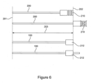
- Figure 6 shows the comparison between the length adjustment of a conventional synthetic rope 200 and the rope 100 according to the present invention.
- the first end 201 and the second end 202 are fixed positions.
- the first end 201 may be located proximate the floating structure, and the second end 202 may be located at the bed of the body of water. It is a requirement of the system that the distance 203 between the first end 201 and the second end 202 of the rope 100, 200 remains constant.
- the anchor 210 at the second end 202 of the rope 200 is fixed relative to the rope 200 such that it is permanently located at the end of the rope 200. Therefore, in order to apply tension to the rope 200 the anchor 210 is moved and the effective length of the rope 200 therefore remains the same including the elongation. This can only be used to make minor adjustments to the rope 200 and eventually the anchor 210 will not be able to account for further elongation.
- the rope 100 according to the present invention effectively utilises an adjustable anchor 212 (the plurality of winding spools 107) which is able to move relative to the rope.
- This allows the effective length of the rope 100 to be adjusted by relocating the position of the anchor 212 relative to the rope 100 as it elongates so that the anchor 212 remains in a fixed position relative to the first end 201 and second end 202.
- This mode allows for continuous length adjustment of the rope 100 as there is no limit as to how much of the rope 100 can be pulled through the anchor 212.
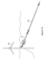
- FIGs 7a and 7b show a floating wind turbine 300 moored to the bed of a body of water via a mooring apparatus.
- the mooring apparatus comprises a conventional rope 200 connected to a rope 100 according to the present invention. Both ropes 100, 200 are connected in series and any length adjustment of the overall mooring apparatus is achieved by the rope 100 using the various components discussed above.
- the rope 100 only forms a small portion of the overall mooring apparatus meaning that it can be easily implemented in conventional mooring systems.
- a rope 100 according to the present invention forms the entire mooring apparatus and extends from the floating wind turbine 300 to the bed of the body of water.
Landscapes
- Chemical & Material Sciences (AREA)
- Engineering & Computer Science (AREA)
- Combustion & Propulsion (AREA)
- Mechanical Engineering (AREA)
- Ocean & Marine Engineering (AREA)
- Wind Motors (AREA)
Priority Applications (1)
| Application Number | Priority Date | Filing Date | Title |
|---|---|---|---|
| EP23250003.3A EP4527729A1 (de) | 2023-09-19 | 2023-09-19 | Verankerungsverfahren und -vorrichtung |
Applications Claiming Priority (1)
| Application Number | Priority Date | Filing Date | Title |
|---|---|---|---|
| EP23250003.3A EP4527729A1 (de) | 2023-09-19 | 2023-09-19 | Verankerungsverfahren und -vorrichtung |
Publications (1)
| Publication Number | Publication Date |
|---|---|
| EP4527729A1 true EP4527729A1 (de) | 2025-03-26 |
Family
ID=88237946
Family Applications (1)
| Application Number | Title | Priority Date | Filing Date |
|---|---|---|---|
| EP23250003.3A Withdrawn EP4527729A1 (de) | 2023-09-19 | 2023-09-19 | Verankerungsverfahren und -vorrichtung |
Country Status (1)
| Country | Link |
|---|---|
| EP (1) | EP4527729A1 (de) |
Citations (3)
| Publication number | Priority date | Publication date | Assignee | Title |
|---|---|---|---|---|
| US20110018275A1 (en) * | 2008-02-20 | 2011-01-27 | Ocean Harvesting Technologies Ab | Wave Power Plant and Transmission |
| AU2015303238A1 (en) * | 2014-08-13 | 2017-02-23 | Bruce Gregory | Improved wave energy converter |
| CN219565400U (zh) * | 2023-01-09 | 2023-08-22 | 广东宇恒空间信息技术有限公司 | 一种浅海区多波束扫海的主动补偿装置 |
-
2023
- 2023-09-19 EP EP23250003.3A patent/EP4527729A1/de not_active Withdrawn
Patent Citations (3)
| Publication number | Priority date | Publication date | Assignee | Title |
|---|---|---|---|---|
| US20110018275A1 (en) * | 2008-02-20 | 2011-01-27 | Ocean Harvesting Technologies Ab | Wave Power Plant and Transmission |
| AU2015303238A1 (en) * | 2014-08-13 | 2017-02-23 | Bruce Gregory | Improved wave energy converter |
| CN219565400U (zh) * | 2023-01-09 | 2023-08-22 | 广东宇恒空间信息技术有限公司 | 一种浅海区多波束扫海的主动补偿装置 |
Similar Documents
| Publication | Publication Date | Title |
|---|---|---|
| US10577056B2 (en) | Mooring pulley tensioning system | |
| US20110278520A1 (en) | Method and device for handling of rope | |
| EP2694427B1 (de) | Spannvorrichtung | |
| EP3615411B1 (de) | Mittellinienspanner | |
| US5779226A (en) | Anchoring system | |
| US7168889B2 (en) | Floating platform having a spoolable tether installed thereon and method for tethering the platform using same | |
| US8001756B2 (en) | Apparatus and method for use in handling an elongate member | |
| EP3277949B1 (de) | Wellenenergiewandler mit vertäuungssystem mit schwimmenden elementen | |
| DK2429933T3 (en) | A device for handling of rope and use thereof | |
| WO2018234763A1 (en) | Pull-in head assembly | |
| Chaplin | Torsional failure of a wire rope mooring line during installation in deep water | |
| AU2008293102B2 (en) | Axial displacement device, line deployment system, and a method for deploying a line | |
| US5566636A (en) | Off shore mooring system | |
| EP4527729A1 (de) | Verankerungsverfahren und -vorrichtung | |
| Wu et al. | Mooring Tensioning Systems for Offshore Platforms: Design, Installation, and Operating Considerations | |
| CN221541872U (zh) | 一种海工平台定位装置 | |
| US6019058A (en) | Looped mooring line and method of installation | |
| WO2005083312A1 (en) | Method and device for temporary or permanent locking of an elongated body such as a rope | |
| WO2012101604A2 (en) | A device for reducing wear on cable in a winch operated wave power plant | |
| Krogstad | Offshore Mooring Machinery For Optimum Utilization Of Steel Wire Rope | |
| SE1530045A1 (sv) | Vågenergiomvandlare med elastiskt förtöjningssystem | |
| Chaplin | Torsional failure of a wire rope mooring line during installation in deep water | |
| SE541894C2 (sv) | Vågenergiomvandlare med förtöjningssystem innefattande flytelement | |
| SE541139C2 (sv) | Vågenergiomvandlare med förtöjningssystem innefattande upplindningsanordning och fastgöringsanordning |
Legal Events
| Date | Code | Title | Description |
|---|---|---|---|
| PUAI | Public reference made under article 153(3) epc to a published international application that has entered the european phase |
Free format text: ORIGINAL CODE: 0009012 |
|
| STAA | Information on the status of an ep patent application or granted ep patent |
Free format text: STATUS: THE APPLICATION HAS BEEN PUBLISHED |
|
| AK | Designated contracting states |
Kind code of ref document: A1 Designated state(s): AL AT BE BG CH CY CZ DE DK EE ES FI FR GB GR HR HU IE IS IT LI LT LU LV MC ME MK MT NL NO PL PT RO RS SE SI SK SM TR |
|
| STAA | Information on the status of an ep patent application or granted ep patent |
Free format text: STATUS: THE APPLICATION IS DEEMED TO BE WITHDRAWN |
|
| 18D | Application deemed to be withdrawn |
Effective date: 20250927 |