EP4528009A1 - Vorrichtung zur behandlung von kleidung - Google Patents
Vorrichtung zur behandlung von kleidung Download PDFInfo
- Publication number
- EP4528009A1 EP4528009A1 EP23824241.6A EP23824241A EP4528009A1 EP 4528009 A1 EP4528009 A1 EP 4528009A1 EP 23824241 A EP23824241 A EP 23824241A EP 4528009 A1 EP4528009 A1 EP 4528009A1
- Authority
- EP
- European Patent Office
- Prior art keywords
- bending portion
- panel
- bracket
- coupling
- treating apparatus
- Prior art date
- Legal status (The legal status is an assumption and is not a legal conclusion. Google has not performed a legal analysis and makes no representation as to the accuracy of the status listed.)
- Pending
Links
Images






Classifications
-
- D—TEXTILES; PAPER
- D06—TREATMENT OF TEXTILES OR THE LIKE; LAUNDERING; FLEXIBLE MATERIALS NOT OTHERWISE PROVIDED FOR
- D06F—LAUNDERING, DRYING, IRONING, PRESSING OR FOLDING TEXTILE ARTICLES
- D06F37/00—Details specific to washing machines covered by groups D06F21/00 - D06F25/00
- D06F37/26—Casings; Tubs
- D06F37/261—Tubs made by a specially selected manufacturing process or characterised by their assembly from elements
- D06F37/263—Tubs made by a specially selected manufacturing process or characterised by their assembly from elements assembled from at least two elements connected to each other; Connecting or sealing means therefor
-
- D—TEXTILES; PAPER
- D06—TREATMENT OF TEXTILES OR THE LIKE; LAUNDERING; FLEXIBLE MATERIALS NOT OTHERWISE PROVIDED FOR
- D06F—LAUNDERING, DRYING, IRONING, PRESSING OR FOLDING TEXTILE ARTICLES
- D06F39/00—Details of washing machines not specific to a single type of machines covered by groups D06F9/00 - D06F27/00
- D06F39/12—Casings; Tubs
-
- D—TEXTILES; PAPER
- D06—TREATMENT OF TEXTILES OR THE LIKE; LAUNDERING; FLEXIBLE MATERIALS NOT OTHERWISE PROVIDED FOR
- D06F—LAUNDERING, DRYING, IRONING, PRESSING OR FOLDING TEXTILE ARTICLES
- D06F29/00—Combinations of a washing machine with other separate apparatus in a common frame or the like, e.g. with rinsing apparatus
-
- D—TEXTILES; PAPER
- D06—TREATMENT OF TEXTILES OR THE LIKE; LAUNDERING; FLEXIBLE MATERIALS NOT OTHERWISE PROVIDED FOR
- D06F—LAUNDERING, DRYING, IRONING, PRESSING OR FOLDING TEXTILE ARTICLES
- D06F29/00—Combinations of a washing machine with other separate apparatus in a common frame or the like, e.g. with rinsing apparatus
- D06F29/005—Combinations of a washing machine with other separate apparatus in a common frame or the like, e.g. with rinsing apparatus the other separate apparatus being a drying appliance
-
- D—TEXTILES; PAPER
- D06—TREATMENT OF TEXTILES OR THE LIKE; LAUNDERING; FLEXIBLE MATERIALS NOT OTHERWISE PROVIDED FOR
- D06F—LAUNDERING, DRYING, IRONING, PRESSING OR FOLDING TEXTILE ARTICLES
- D06F31/00—Washing installations comprising an assembly of several washing machines or washing units, e.g. continuous flow assemblies
-
- D—TEXTILES; PAPER
- D06—TREATMENT OF TEXTILES OR THE LIKE; LAUNDERING; FLEXIBLE MATERIALS NOT OTHERWISE PROVIDED FOR
- D06F—LAUNDERING, DRYING, IRONING, PRESSING OR FOLDING TEXTILE ARTICLES
- D06F37/00—Details specific to washing machines covered by groups D06F21/00 - D06F25/00
- D06F37/20—Mountings, e.g. resilient mountings, for the rotary receptacle, motor, tub or casing; Preventing or damping vibrations
- D06F37/22—Mountings, e.g. resilient mountings, for the rotary receptacle, motor, tub or casing; Preventing or damping vibrations in machines with a receptacle rotating or oscillating about a horizontal axis
-
- D—TEXTILES; PAPER
- D06—TREATMENT OF TEXTILES OR THE LIKE; LAUNDERING; FLEXIBLE MATERIALS NOT OTHERWISE PROVIDED FOR
- D06F—LAUNDERING, DRYING, IRONING, PRESSING OR FOLDING TEXTILE ARTICLES
- D06F39/00—Details of washing machines not specific to a single type of machines covered by groups D06F9/00 - D06F27/00
- D06F39/001—Arrangements for transporting, moving, or setting washing machines; Protective arrangements for use during transport
-
- D—TEXTILES; PAPER
- D06—TREATMENT OF TEXTILES OR THE LIKE; LAUNDERING; FLEXIBLE MATERIALS NOT OTHERWISE PROVIDED FOR
- D06F—LAUNDERING, DRYING, IRONING, PRESSING OR FOLDING TEXTILE ARTICLES
- D06F58/00—Domestic laundry dryers
- D06F58/20—General details of domestic laundry dryers
Definitions
- the present disclosure relates to an apparatus for treating laundry.
- a laundry treating apparatus is a device for performing a treatment required for laundry, such as by putting laundry, a bedding, etc. into a drum and removing contamination on the laundry or drying the laundry.
- the laundry treating apparatus may perform processes of washing, rinsing, dehydrating, drying, etc.
- the laundry treating apparatus may include a cabinet forming an exterior thereof, a tub accommodated in the cabinet, a drum rotatably mounted in the tub to have laundry put therein, and a detergent supply device configured to supply detergent to the inside of the drum.
- the laundry treating apparatus may remove moisture from the laundry by providing dry air to the laundry.
- the laundry treating apparatus may include a cabinet, a drum rotatably provided in the cabinet, and a heating unit configured to heat or dry air provided to the laundry. As the dry air is supplied to the laundry accommodated in the drum, the moisture present in the laundry may be removed by being evaporated by the dry air, and thus the moisture of the laundry may be removed.
- the laid-open document 10-2005-0054201 A1 discloses a laundry treating apparatus.
- An exterior of the laundry treating apparatus is formed by a cabinet.
- the cabinet may include a front panel, a side panel, a rear panel, and a top panel. According to the related art, each panel has a structure directly coupled to each other.
- One object of the present disclosure is to provide a structure capable of reducing vibration noise in coupling between panels of a cabinet forming an exterior of a laundry treating apparatus.
- Another object of the present disclosure is to provide a structure capable of increasing assembly convenience of an assembly worker in a process of assembling a cabinet forming an exterior of a laundry treating apparatus.
- Further object of the present disclosure is to provide a structure capable of adjusting the depth of a laundry treating apparatus as needed when manufacturing a laundry treating apparatus.
- the laundry treating apparatus may include a drum in which clothes are accommodated and a cabinet accommodating the drum, wherein the cabinet includes a front panel provided at a front side, a side panel provided at both lateral sides and having a rear bending portion having a rear side bent inward, a rear panel having a first bending portion provided at a rear side and having both ends facing the side panel to be bent forward, and a bracket including a first coupling portion having at least a portion facing the first bending portion and coupled to the first bending portion and a second coupling portion formed to be bent from the first coupling portion, wherein the rear panel and the side panel are coupled to each other through the bracket, wherein the first bending portion of the rear panel is coupled to the first coupling portion, and wherein the rear bending portion of the side panel is coupled to the second coupling portion.
- the second coupling portion may extend from the first coupling portion at a side adjacent to a rear plate forming a rear surface of the rear panel.
- the bracket may include a recessed portion recessed inward at least in part.
- a recessed portion that does not contact the first bending portion may be formed in at least a portion of the first coupling portion of the bracket.
- At least a portion of the second coupling portion of the bracket may have a recessed portion that is not in contact with the rear bending portion.
- a vertical length of the bracket may be shorter than a height of the rear panel.
- the first coupling portion may include a protrusion protruding toward the first bending portion, and a locking hole through which the protrusion passes may be formed at a position corresponding to the protrusion in the first bending portion.
- the protrusion may include a first hook portion extending in one direction along a vertical direction from an inner portion passing through the locking hole.
- the protrusion may further include a second hook portion extending in the other direction along the vertical direction from the inner portion passing through the locking hole.
- the bracket may be formed in a vertically symmetrical shape.
- first bending portion of the rear panel, the first coupling portion of the bracket, the rear bending portion of the side panel, and the second coupling portion of the bracket may be coupled by a fastening member.
- a raised portion raised toward the rear bending portion may be formed in the second coupling portion of the bracket.
- the raised portion may be formed around a through-hole through which a fastening member for coupling with the rear bending portion passes and may be in contact with the rear bending portion.
- the raised portion may be formed in a ring shape surrounding the through-hole.
- the first bending portion of the rear panel and the rear bending portion of the side panel may be provided to be coupled to each other.
- the rear panel may further include a second bending portion bent outward from the first bending portion, and the second coupling portion may extend to be at least partially parallel to the second bending portion.
- the apparatus may further include a rigidity reinforcing portion extending forward from the second coupling portion on the opposite side of the side on which the first coupling portion is formed.
- vibration noise during operation may be reduced from a coupling structure between panels of a cabinet forming an exterior of a laundry treating apparatus.
- the assembly convenience of an assembly worker may be increased in the process of assembling a cabinet forming an exterior of a laundry treating apparatus.
- a depth of a laundry treating apparatus may be adjusted as necessary in the course of manufacturing a laundry treating apparatus.
- the term "and/or" includes a combination of a plurality of listed items or any one of a plurality of listed items.
- 'a or b' may include 'a', 'b', or 'both a and b'.
- FIG. 1 illustrates a laundry treating apparatus 1 according to an embodiment of the present disclosure.
- the laundry treating apparatus 1 includes a first treating apparatus 10, a second treating apparatus 20, and a control panel 200.
- a forward direction (+X), a backward direction (-X), a first lateral direction (+Y), a second lateral direction (-Y), an upward direction (+Z), and a downward direction (-Z) for each component may be defined as the same terms.
- a front-rear direction (+X, -X) of the first treating apparatus 10 may be defined to be the same as a front-rear direction of the second treating apparatus 20, the control panel 200, and the like, and a lateral direction (Y) and a top-bottom direction (Z) may also be defined in the same manner.
- the first treating apparatus 10 and the second treating apparatus 20 may be provided as various types for treating laundry such as a washing machine for washing laundry, a dryer for drying laundry, and/or the like.
- the first treating apparatus 10 may be a washing machine
- the second treating apparatus 20 may be a dryer. Both the first treating apparatus 10 and the second treating apparatus 20 may be washing machines or dryers, the first treating apparatus 10 may be a dryer, the second treating apparatus 20 may be a washing machine, or the first treating apparatus 10 and the second treating apparatus 20 may include various apparatuses for treating other laundry.
- the first treating apparatus 10 located at a lower side may correspond to a washing machine for washing laundry.
- a first drum 12 and a tub 14, in which laundry is accommodated, may be provided in the first treating apparatus 10.
- the first drum 12 inside the first treating apparatus 10 may be rotatably provided inside the tub 14.
- the second treating apparatus 20 is located above the first treating apparatus 10.
- the first treating apparatus 10 supports the second treating apparatus 20.
- the second treating apparatus 20 may correspond to a dryer for drying laundry.
- the second treating apparatus 20 may include a first drum 12 and a tub 14 in which laundry are accommodated.
- the first treating apparatus 10 may include a first cabinet 110 forming an exterior of the first treating apparatus 10.
- the first cabinet 110 may be provided with a first front panel 112 at a front side thereof.
- a laundry opening communicating with the first drum 12 may be formed in the first front panel 112.
- the laundry opening may be opened and closed by a first cabinet door 17.
- the first drum 12 of the first treating apparatus 10 according to an embodiment has a rotation axis parallel to a front-rear direction (+X, -Y).
- the first treating apparatus 10 may be provided with a first left panel 115 in one direction (+Y).
- a first right panel 116 (see FIG. 2 ) may be provided in the other lateral direction (-Y) of the first treating apparatus 10.
- a first rear panel (not shown) may be provided at a rear side of the first treating apparatus 10.
- a first upper panel (not shown) may be provided at an upper side of the first treating apparatus 10.
- a first lower panel 117 (see FIG. 2 ) may be provided at a lower side of the first treating apparatus 10.
- the first front panel 112, the first side panel 115, the first rear panel (not shown), the first upper panel 119, and the first lower panel (not shown) may be combined with each other to form the first cabinet 110, and may have a coupling relationship with each other.
- the first cabinet 110 may form a space in which internals of the first treating apparatus 10 such as the first drum 12 are provided.
- first treating apparatus 10 laundry and the like for treatment is put into the first cabinet 110 through the laundry opening so as to be accommodated in the first drum 12, and thus, a treatment process by the first treating apparatus 10 may be performed.
- a detergent opening is formed in the first front panel 112, and a detergent storage unit 16 is provided by being inserted into the detergent opening.
- the first treating apparatus 10 may be disposed on the ground, and the detergent storage unit 16 may be located above the laundry opening of the first treating apparatus 10 so that the detergent storage unit 16 may be conveniently inserted and withdrawn.
- the detergent storage unit 16 may be located between the laundry opening of the first treating apparatus 10 and the control panel 200. That is, the detergent storage unit 16 may be located above the laundry opening of the first treating apparatus 10, and may be located below the control panel 200.
- the detergent storage unit 16 may be inserted into or withdrawn from the first cabinet 110 by a user. For example, the user may separate the detergent storage unit 16 from the first cabinet 110, store the detergent in the detergent storage unit 16, and then insert the detergent storage unit 16 into the first cabinet 110.
- the first front panel 112 has a filter opening into which a filter unit 18 for collecting foreign substances from wash water is inserted, and the filter unit 18 is inserted into the filter opening.
- the filter unit 18 may be provided at one side of a lower portion of the first front panel 112.
- the filter unit 18 may be inserted into the first cabinet 110 through the filter opening, and may be connected to a passage of the wash water discharged from the tub 14. After the washing process is performed, the filter unit 18 may filter out foreign substances from the wash water discharged from the tub 14.
- Roles of the filter unit 18 are not necessarily limited thereto, and may be provided to filter foreign substances from various objects as necessary.
- the filter unit 18 may be provided to filter out foreign substances from the wash water for performing the washing process before the washing process is performed.
- a user may insert/withdraw the filter unit 18 into/from the first cabinet 110 through the filter opening.
- the withdrawn filter unit 18 may be reused or replaced after being washed.
- the filter unit 18 may have a relatively longer period of insertion and withdrawal in relation to the detergent storage unit 16, and accordingly, in an embodiment of the present disclosure, the detergent opening in which the detergent storage unit 16 having a relatively short insertion and withdrawal period is introduced may be disposed at an upper portion side of the first front panel 112.
- the filter opening into which the filter unit 18 having a relatively long insertion and withdrawal period is inserted may be disposed at a lower portion side of the first front panel 112 to improve convenience in use and may implement a structure of the first front panel 112 having excellent space utilization.
- a wash water discharge passage connected to the tub 14 inside the first cabinet 110 may be located at a lower side within the first cabinet 110 to facilitate the discharge of wash water, and in an embodiment of the present disclosure, the filter unit 18 may be provided at the lower side of the first cabinet 110 to be efficiently connected to the wash water discharge passage.
- the first treating apparatus 10 may be provided with a first device controller 19.
- the first device controller 19 is configured to control various devices constituting the first treating apparatus 10.
- the first device controller 19 is disposed inside the first cabinet 110.
- the first device controller 19 may include a circuit board and electrical components mounted on the circuit board.
- the first device controller 19 may check information corresponding to a manipulation signal received from the control panel 200 in the memory, and perform a device control corresponding to the manipulation signal.
- the first device controller 19 may transmit a state of the first treating apparatus 10 to the control panel 200.
- the second treating apparatus 20 may include a second cabinet 120 forming an exterior of the second treating apparatus 20.
- the second cabinet 120 may include a second front panel 122 provided at a front side thereof.
- a laundry opening communicating with a second drum 22 may be formed in the second front panel 122.
- the laundry opening may be opened and closed by a second cabinet door 27.
- the second treating apparatus 20 may be provided with a second left panel 125 in one lateral direction (+Y).
- a second right panel 126 (see FIG. 2 ) may be provided in the other lateral direction (-Y) of the second treating apparatus 20.
- a second rear panel (not shown) may be provided at a rear side of the second treating apparatus 20.
- a second upper panel 127 may be provided at an upper side of the second treating apparatus 20.
- a base 500 (see FIG. 2 ) may be provided at a lower side of the second treating apparatus 20.
- the second front panel 122, the second side panel 125, the second rear panel 128 (see FIG. 2 ), the second upper panel 127, and the base 500 may be combined with each other to form a second cabinet 120, and may have a coupling relationship with each other.
- the second cabinet 120 may form a space in which internals constituting the second treating apparatus 20 such as a second drum 22 are provided.
- Laundry and the like that requires treatment is put into the second cabinet 120 through a laundry opening of the second treating apparatus 20 so as to be accommodated in the second drum 22.
- the laundry accommodated in the second drum 22 may be subjected to a treatment process such as washing, drying, and the like by the second treating apparatus 20.
- the laundry opening is provided in the second front panel 122 together with the second cabinet door 27.
- the second drum 22 accommodated in the second treating apparatus 20 has a rotation axis parallel to the front-rear direction (X).
- the second treating apparatus 20 is disposed above the first treating apparatus 10.
- a lower portion of the first treating apparatus 10 may be coupled to an upper portion of the second treating apparatus 20.
- the upper portion of the first treating apparatus 10 may have a structure supporting the second treating apparatus 20.
- a first upper panel (not shown) of the first treating apparatus 10 may directly or indirectly support t a base 500 of the second treating apparatus 20.
- the second treating apparatus 20 may be provided with a second device controller 29.
- the second device controller 29 controls various devices constituting the second treating apparatus 2.
- the second device controller 29 is disposed inside the second cabinet 120.
- the second device controller 29 may include a circuit board and electrical components mounted on the circuit board.
- the second device controller 29 may check information corresponding to a manipulation signal received from the control panel 200 in the memory, and control a device corresponding to the manipulation signal.
- the second device controller 29 may transmit a state of the second treating apparatus 20 to the control panel 200.
- the control panel 200 is disposed between the first front panel 112 and the second front panel 122. Since the control panel 200 is provided between the first front panel 112 and the second front panel 122, which are approximately the height corresponding to a waist of a user, the control panel 200 may secure a convenient height for the user to manipulate.
- the control panel 200 may be signal-connected to at least one of the first treating apparatus 10 and the second treating apparatus 20. In an embodiment, the control panel 200 is signal-connected to the first treating apparatus 10 and the second treating apparatus 20. In an embodiment, the control panel 200 is signal-connected to the first device controller 19 and/or the second treating apparatus 20.
- a User Interface (UI) is displayed on a front surface of the control panel 200. The user may control the first treating apparatus 10 and/or the second treating apparatus 20 through the control panel 200.
- UI User Interface
- a rear bracket 500 is provided behind the laundry treating apparatus 1.
- the rear bracket 500 is coupled to the first treating apparatus 10 and the second treating apparatus 20.
- the rear bracket 500 is disposed at a rear upper portion of the first treating apparatus 10 and at the same time is disposed at a rear lower portion of the second treating apparatus 20.
- a handle for a carrier is formed in the rear bracket 500. The carrier may more easily move the laundry treating apparatus 1 using the handle formed on the rear bracket 500.
- FIG. 2 is an exploded perspective diagram illustrating a coupling between a rear panel and a side panel of a cabinet constituting a laundry treating apparatus according to an embodiment of the present disclosure. This will be described with reference to FIG. 2 .
- the second cabinet 120 of the second treating apparatus 20 will be described as an example.
- the present disclosure may also be applied to the first cabinet 110 constituting the first treating apparatus 10.
- the laundry treating apparatus may be applied to a laundry treating apparatus including a single treating apparatus instead of a laundry treating apparatus in which a plurality of treating apparatuses are stacked up and down.
- the structure of the present embodiment is applied to the second treating apparatus 20 in the laundry treating apparatus 1 having a structure in which the first treating apparatus 10 and the second treating apparatus 20 are stacked, it is possible to effectively reduce vibration noise caused by a coupling portion between components of the cabinet, which may mainly occur in the upper portion.
- a left side of a second rear panel 128 is coupled to a second left panel 125 through a first bracket 300-1.
- a right side of the second rear panel 128 is coupled to a second right panel 126 through a second bracket 300-2.
- the first bracket 300-1 and the second bracket 300-2 may be substantially the same brackets.
- the second bracket 300-2 may be a vertically inverted version of the first bracket 300-1.
- first bracket 300-1 and the second bracket 300-2 are collectively referred to as a bracket 300.
- the coupling method of the second rear panel 128 and the second left panel 125 by the first bracket 300-1 is substantially the same as the coupling method of the second rear panel 128 and the second right panel 126 by the second bracket 300-2, another explanation will be replaced with one explanation. Since the second left side panel 125 and the second right side panel 126 are face-symmetric with each other and substantially have the same configuration, the other explanation will be replaced with the description of either the second left side panel 125 or the second right side panel 126.
- the second rear panel 128 includes a rear plate 128 a forming a rear surface of the second cabinet 120.
- the second rear panel 128 includes a first bending portion 128b bent forward from both side ends of the rear plate 128a.
- the second rear panel 128 includes a second bending portion 128c bent outward from a front end of the first bending portion 128b.
- the second right panel 126 includes a side plate 126a forming a side surface of the second cabinet 120.
- the second right panel 126 includes a rear bending portion 126b bent inward from a rear side of the side plate 126a.
- the rear bending portion 126b is located behind the second bending portion 128c of the second rear panel 128.
- FIG. 3 is an exploded perspective diagram illustrating a structure in which a bracket and a rear panel are coupled according to an embodiment of the present disclosure.
- the bracket 300 is located between the second bending portion 128c and the rear bending portion 126b.
- the bracket 300 couples the second rear panel 128 and the second right panel 126.
- one bracket 300 is further provided to couple the second rear panel 128 and the second left panel 125.
- the bracket 300 includes a first coupling portion 310 and a second coupling portion 320.
- the first coupling portion 310 faces the first bending portion 128b.
- the second coupling portion 320 is bent and extends from the first coupling portion 310.
- the first coupling portion 310 and the second coupling portion 320 may be formed by bending one plate.
- the bracket 300 may be formed by coupling (e.g. welding) a plate forming the first coupling portion 310 and a plate forming the second coupling portion 320.
- the first coupling portion 310 may have a plate shape extending in the vertical direction.
- the second coupling portion 320 may be a plate shape bent from a side surface of the first coupling portion 310 and formed long in the vertical direction.
- the second coupling portion 320 extends from the first coupling portion 310 at a side adjacent to the rear plate 128a of the second rear panel 128.
- a width of the first coupling portion 310 is formed to be narrower than a width of the first bending portion 128b.
- a width of the second coupling portion 320 may be formed to be narrower than a width of the second bending portion 128c.
- the first coupling portion 310 may be formed of a plurality of separated plates. In an embodiment, a plurality of the plates constituting the first coupling portion 310 may be formed by cutting one plate.
- the bracket 300 may be formed of a metal material.
- the length (height) of the bracket 300 in the vertical direction may be shorter than that of the second rear panel 128.
- the vertical length (height) of the second side panel 125/126 may be the same as that of the second rear panel 128.
- the vertical length of the bracket 300 is shorter than the height of the second side panel 125/126.
- the first coupling portion 310 includes a first fixing portion 311, a second fixing portion 312, a third fixing portion 313, a first temporary fixing portion 314, and a second temporary fixing portion 315.
- the first fixing portion 311 is formed at an upper part of the first coupling portion 310.
- the third fixing portion 313 is formed at a lower part of the first coupling portion 310.
- the second fixing portion 312 is formed in the middle of the first coupling portion 310.
- the first temporary fixing portion 314 is formed between the first fixing portion 311 and the second fixing portion 312.
- the second temporary fixing portion 315 is formed between the second fixing portion 312 and the third fixing portion 313.
- a coupling hole for the coupling by a fastening member 900a is formed in the first fixing portion 311.
- a through-hole for the coupling by the fastening member 900b is formed in the second fixing portion 312.
- a through-hole for the coupling by a fastening member 900c is formed in the third fixing portion 313.
- a through-hole is formed at a position corresponding to the through-hole formed in each of the first fixing portion 311, the second fixing portion 312, and the third fixing portion 313 of the first bending portion 128b.
- the first fixing portion 311 is coupled to the first bending portion 128b by the fastening member 900a.
- the second fixing portion 312 is coupled to the first bending portion 128b by the fastening member 900b.
- the third fixing portion 313 is coupled to the first bending portion 128b by the fastening member 900b.
- the fastening member 900 may be provided as a screw, a rivet, or the like.
- a first protrusion 314c for temporary fixing with the first bending portion 128b is formed at the first temporary fixing portion 314.
- the first protrusion 314c may extend in an inner direction of the first bending portion 128b, and the hook portions 314ca and 314cb (see FIG. 4 ) may be formed in the vertical direction.
- the first protrusion 314c may have a vertically symmetrical shape.
- the first protrusion 314c may have an arrow shape.
- the first protrusion 314c passes through a locking hole 128bc formed in the first bending portion 128b, and a portion of the first protrusion 314c is located inside the first bending portion 128b.
- the bracket 300 may be temporarily coupled to the second rear panel 128.
- the hook portions 314ca and 314cb prevent the bracket 300 from being separated from the locking hole 128bc.
- a second protrusion 315c for temporary fixing to the first bending portion 128b is formed at the second temporary fixing portion 315.
- the second protrusion 315c may extend in the inner direction of the first bending portion 128b, and a locking protrusion may be formed in the vertical direction.
- the second protrusion 315c may have a vertically symmetrical shape.
- the second protrusion 315c may have an arrow shape.
- the bracket 300 may be formed in a vertically symmetrical shape from the center line of the second fixing portion 312. By forming the bracket 300 in a vertically symmetrical shape, the first bracket 300-1 and the second bracket 300-2 may be provided as the same component. In an embodiment, the second bracket 300-2 is a vertically inverted version of the first bracket 300-1.
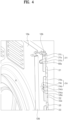
- FIG. 4 is a side view diagram illustrating a state in which a bracket and a rear panel are coupled according to an embodiment of the present disclosure. A side panel will be omitted to clearly show the bracket. The following description will be made with reference to FIG. 4 .
- the bracket 300 is coupled to the first bending portion 128b of the second rear panel 128.
- the first fixing portion 311 may include a surface contact portion 311a and a recessed portion 311c.
- the recessed portion 311c is formed in a manner of being raised from the surface contact portion 311 an and does not directly contact the first bending portion 128b.
- a fastening portion 311b which is in direct contact with the first bending portion 128b, protrudes forward from the surface contact portion 311a.
- a through-hole is formed in the fastening portion 311b, and the first fixing portion 311 and the first bending portion 128b are coupled to each other through a fastening member 900a that passes through the through-hole.
- the inventors of the present disclosure recognize that, when the rear panel, the side panel, and the like, which are components constituting the cabinet of the laundry treating apparatus 1, are coupled to each other, vibration noise is generated when surfaces touching each other are increased. Accordingly, in coupling the rear panel and the side panel through the bracket 300, a contact area of a coupling surface is reduced, thereby reducing the vibration noise. That is, if the recessed portion 311c is formed, a contact area may be reduced, and a side effect of reducing vibration noise may be obtained.
- the first temporary fixing portion 314 may include a surface contact portion 314a and a recessed portion 314b.
- the recessed portion 314b is formed to be raised from the surface contact portion 314a and does not directly contact the first bending portion 128b. According to an embodiment of the present disclosure, since the recessed portion 314b is formed, vibration noise may be reduced.
- the first protrusion 314c may extend from the recessed portion 311c.
- the first protrusion 314c may extend from the recessed portion 314b to the inside of the first bending portion 128b.
- the first protrusion 314c is inserted through the locking hole 128bc.
- the first protrusion 314c may include a first hook portion 314ca and a second hook portion 314cb.
- the first hook portion 314ca and the second hook portion 314cb protrude from the inside of the first protrusion 314c inserted into the locking hole 128bc.
- the first hook portion 314ca extends in one direction along the vertical direction at an inner portion passing through the locking hole 128bc.
- the first hook portion 314ca extends downward from the inner portion passing through the locking hole 128bc.
- the second hook portion 314cb extends in the other direction along the vertical direction from the an inner portion passing through the locking hole 128bc.
- the second hook portion 314cb extends upward from the inner portion passing through the locking hole 128bc. Since the first hook portion 314ca is formed in the first protrusion 314c, the bracket 300 may be caught and temporarily fixed to the second rear panel 128. As the second hook portion 314cb is further formed, when the bracket 300 is inverted in the vertical direction and is used on the opposite side, since the second hook portion 314cb is positioned downward, the bracket 300 may be caught by the second rear panel 126 to be temporarily fixed thereto. By forming the first hook portion 314ca and the second hook portion 314cb in the first protrusion 314c, the first bracket 300-1 and the second bracket 300-2 may be provided as the same component.
- a recessed portion 321 may also be formed in at least a portion of the second coupling portion 320.
- the recessed portion 321 is raised in a direction that does not contact the rear bending portion 126 b.
- rigidity reinforcing portions 331, 332, and 333 extending from the second coupling portion 320 may be further included.
- the rigidity reinforcing portions 331, 332, and 333 extend forward from the second coupling portion 320.
- the rigidity reinforcing portions 331, 332, and 333 may extend in a direction parallel to the second left panel 125 (see FIG. 2 ).
- the rigidity reinforcing portions 331, 332, and 333 extend from the second coupling portion 320 opposite to the side from which the first coupling portion 310 extends.
- One or more embossing portions 332a are formed in the rigidity reinforcing portions 331, 332, and 333. The embossing portion 332a may increase rigidity of the second coupling portion 320.
- FIG. 5 is a rear diagram illustrating a state in which a bracket and a rear panel are coupled according to an embodiment of the present disclosure. A side panel will not be illustrated to clearly show the bracket. This following description will be made with reference to FIG. 5 .
- a recessed portion 321, an opening 322a, and a through-hole 325 may be formed in the second coupling portion 320.
- the opening 322a allows an assembly worker to approach the through-hole 129a of the second bending portion 128c and couple a configuration other than the second bending portion 128c through a fastening member passing through the through-hole 129 a.
- the through-hole 325 may be penetrated by the fastening member, and the rear bending portion 126b of the second left panel 125 and the bracket 300 may be coupled to each other through the fastening member.
- a raised portion 325a that is raised toward the rear bending portion 126b is formed around the through-hole 325.
- the raised portion 325a is formed in a ring shape surrounding the through-hole 325.
- the raised portion 325a may be formed in a donut shape.
- the raised portion 325a is in contact with the rear bending portion 126b. Since the bracket 300 contacts the rear bending portion 126b through the raised portion 325a, a contact area of a coupling surface may be reduced. As a result, vibration noise may be effectively reduced.
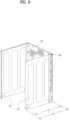
- FIG. 6 is a perspective diagram illustrating a state in which a rear panel and a side panel of a cabinet constituting a laundry treating apparatus according to an embodiment of the present disclosure are coupled by a bracket. This will be described with reference to FIG. 6 .
- the second left panel 125 and the second rear panel 128 may be coupled through the bracket 300.
- the second right panel 126 and the second rear panel 128 may be coupled through the bracket 300.
- a depth of the cabinet except for the second front panel 122 may be formed to be D 1.
- the second left panel 125 and the second rear panel 128 may be directly coupled to each other.
- the second right panel 126 may be directly coupled with the second rear panel 128.
- the rear bending portion 125b of the second left panel 125 and the second bending portion 128c of the second rear panel 128 may be coupled to each other.
- the depth of the cabinet except for the second front panel 122 may be formed to be D2.
- D2 is longer than D1. That is, the depth of the cabinet may be adjusted using the bracket 300.
- the second bending portion 128c of the second rear panel 128 and the second coupling portion 320 of the bracket 300 are configured to be substantially parallel to each other.
- the coupling portion 129b formed in the second bending portion 128c is configured to correspond to a coupling portion (not shown) formed in the rear bending portion 126b of the second left panel 125.
- the second bending portion 128c of the second rear panel 128 may be coupled to the rear bending portion 126b of the second right panel 126 in direct or through the bracket 300. Accordingly, the depth of the laundry treating apparatus may be adjusted as necessary when the laundry treating apparatus is manufactured (see FIG. 9).
- FIG. 7 is a partial cross-sectional diagram of a laundry treating apparatus according to an embodiment of the present disclosure.
- FIG. 7 shows a cross-sectional view of a rear panel and a side panel that are coupled by a bracket.
- FIG. 8 is a cross-sectional perspective diagram illustrating a portion A in FIG. 6 . The following description will be made with reference to FIG. 7 and FIG. 8 .
- the second right panel 126 and the second rear panel 128 are coupled to each other through the bracket 300. At least a portion of the first coupling portion 310 of the bracket 300 is in surface contact with the first bending portion 128b of the second rear panel 128. The first coupling portion 310 of the bracket 300 is coupled to the first bending portion 128b of the second rear panel 128. The coupling may be performed by a fastening member 900b. At least a portion of the second coupling portion 320 of the bracket 300 is in surface contact with the rear bending portion 126b of the second right panel 126. The second coupling portion 320 of the bracket 300 is coupled to the rear bending portion 126b of the second right panel 126.
- the coupling may be performed by a fastening member 900d.
- the second coupling portion 320 of the bracket 300 is configured such that the raised portion 325a and the rear bending portion 126b are in surface contact with each other, thereby reducing a contact area.
- the first protrusion 314c formed in the first temporary fixing portion 314 extends in the inner direction of the first bending portion 128b and passes through the locking hole 128bc formed in the first bending portion 128b so as to be located inside the cabinet 120.
- the first protrusion 314c may have a vertically symmetrical shape. In an embodiment, the first protrusion 314c may have an arrow shape.
- the bracket 300 may be temporarily coupled to the second rear panel 128.
- the rigidity reinforcing portion 332 does not contact the side plate 126a of the second right panel 126. Since the rigidity reinforcing portions 331, 332, and 333 are not in contact with the side plate 126a of the second right panel 126, rigidity may be reinforced and vibration noise caused by the contact may be reduced.
Landscapes
- Engineering & Computer Science (AREA)
- Textile Engineering (AREA)
- Main Body Construction Of Washing Machines And Laundry Dryers (AREA)
Applications Claiming Priority (2)
| Application Number | Priority Date | Filing Date | Title |
|---|---|---|---|
| KR1020220073556A KR102808506B1 (ko) | 2022-06-16 | 2022-06-16 | 의류처리장치 |
| PCT/KR2023/008271 WO2023244028A1 (ko) | 2022-06-16 | 2023-06-15 | 의류처리장치 |
Publications (2)
| Publication Number | Publication Date |
|---|---|
| EP4528009A1 true EP4528009A1 (de) | 2025-03-26 |
| EP4528009A4 EP4528009A4 (de) | 2025-10-15 |
Family
ID=89191570
Family Applications (1)
| Application Number | Title | Priority Date | Filing Date |
|---|---|---|---|
| EP23824241.6A Pending EP4528009A4 (de) | 2022-06-16 | 2023-06-15 | Vorrichtung zur behandlung von kleidung |
Country Status (6)
| Country | Link |
|---|---|
| US (1) | US20250369176A1 (de) |
| EP (1) | EP4528009A4 (de) |
| KR (2) | KR102808506B1 (de) |
| CN (1) | CN119384531A (de) |
| AU (1) | AU2023291023B2 (de) |
| WO (1) | WO2023244028A1 (de) |
Family Cites Families (11)
| Publication number | Priority date | Publication date | Assignee | Title |
|---|---|---|---|---|
| FR1520703A (fr) * | 1967-03-01 | 1968-04-12 | Chalectro Cie Des Machiens A L | Machine à laver à châssis en cage |
| ES2002894A6 (es) * | 1986-10-30 | 1988-10-01 | Domar Sa | Perfeccionamientos en los muebles para maquinas de lavar ropa |
| CN1309896C (zh) * | 2002-07-31 | 2007-04-11 | Lg电子株式会社 | 用于家用电器的箱体 |
| KR20040074318A (ko) * | 2003-02-17 | 2004-08-25 | 엘지전자 주식회사 | 드럼세탁기의 캐비닛 구조 |
| US20050115105A1 (en) * | 2003-11-28 | 2005-06-02 | Ahn Jeung G. | Home appliance assembly and method of manufacturing the same |
| KR101073903B1 (ko) | 2003-12-04 | 2011-10-18 | 엘지전자 주식회사 | 의류건조기 |
| KR101021716B1 (ko) * | 2003-12-19 | 2011-03-15 | 엘지전자 주식회사 | 건조기의 사이드 프레임 조립구조 |
| KR100701181B1 (ko) * | 2006-03-29 | 2007-03-28 | 주식회사 대우일렉트로닉스 | 끼움 결합방식의 프레임 탑이 구비되는 건조기 |
| KR101698855B1 (ko) * | 2009-05-28 | 2017-01-24 | 엘지전자 주식회사 | 세탁장치 |
| CN201447592U (zh) * | 2009-08-12 | 2010-05-05 | 龚银其 | 洗衣机外壳 |
| CN110629484B (zh) * | 2019-09-17 | 2021-09-21 | 无锡小天鹅电器有限公司 | 衣物处理装置的框架组件和衣物处理装置 |
-
2022
- 2022-06-16 KR KR1020220073556A patent/KR102808506B1/ko active Active
-
2023
- 2023-06-15 US US18/872,776 patent/US20250369176A1/en active Pending
- 2023-06-15 CN CN202380047415.1A patent/CN119384531A/zh active Pending
- 2023-06-15 EP EP23824241.6A patent/EP4528009A4/de active Pending
- 2023-06-15 AU AU2023291023A patent/AU2023291023B2/en active Active
- 2023-06-15 WO PCT/KR2023/008271 patent/WO2023244028A1/ko not_active Ceased
-
2025
- 2025-05-07 KR KR1020250059072A patent/KR20250067792A/ko active Pending
Also Published As
| Publication number | Publication date |
|---|---|
| AU2023291023A1 (en) | 2024-12-12 |
| KR20250067792A (ko) | 2025-05-15 |
| CN119384531A (zh) | 2025-01-28 |
| KR20230172865A (ko) | 2023-12-26 |
| WO2023244028A1 (ko) | 2023-12-21 |
| US20250369176A1 (en) | 2025-12-04 |
| EP4528009A4 (de) | 2025-10-15 |
| AU2023291023B2 (en) | 2026-03-26 |
| KR102808506B1 (ko) | 2025-05-16 |
Similar Documents
| Publication | Publication Date | Title |
|---|---|---|
| JP7802723B2 (ja) | 衣類処理装置 | |
| CN113355853B (zh) | 衣物处理装置 | |
| JP7676451B2 (ja) | 衣類処理装置 | |
| JP7783215B2 (ja) | 衣類処理装置 | |
| US7607327B2 (en) | Drum type washing machine | |
| EP2065506B1 (de) | Waschmaschine | |
| EP4528009A1 (de) | Vorrichtung zur behandlung von kleidung | |
| KR102711599B1 (ko) | 의류처리장치 | |
| KR102536870B1 (ko) | 의류처리장치 | |
| US20250361664A1 (en) | Apparatus for treating laundry | |
| EP4530387A1 (de) | Vorrichtung zur behandlung von wäsche | |
| KR102794801B1 (ko) | 의류처리장치 | |
| KR102814548B1 (ko) | 의류처리장치 | |
| RU2363788C1 (ru) | Стиральная или сушильная машина, содержащая устройство управления со сменным положением | |
| KR20090024470A (ko) | 세탁물 처리기기의 히터 장착 구조 |
Legal Events
| Date | Code | Title | Description |
|---|---|---|---|
| STAA | Information on the status of an ep patent application or granted ep patent |
Free format text: STATUS: THE INTERNATIONAL PUBLICATION HAS BEEN MADE |
|
| PUAI | Public reference made under article 153(3) epc to a published international application that has entered the european phase |
Free format text: ORIGINAL CODE: 0009012 |
|
| STAA | Information on the status of an ep patent application or granted ep patent |
Free format text: STATUS: REQUEST FOR EXAMINATION WAS MADE |
|
| 17P | Request for examination filed |
Effective date: 20241220 |
|
| AK | Designated contracting states |
Kind code of ref document: A1 Designated state(s): AL AT BE BG CH CY CZ DE DK EE ES FI FR GB GR HR HU IE IS IT LI LT LU LV MC ME MK MT NL NO PL PT RO RS SE SI SK SM TR |
|
| REG | Reference to a national code |
Ref country code: DE Ref legal event code: R079 Free format text: PREVIOUS MAIN CLASS: D06F0037220000 Ipc: D06F0029000000 |
|
| DAV | Request for validation of the european patent (deleted) | ||
| DAX | Request for extension of the european patent (deleted) | ||
| A4 | Supplementary search report drawn up and despatched |
Effective date: 20250911 |
|
| RIC1 | Information provided on ipc code assigned before grant |
Ipc: D06F 29/00 20060101AFI20250905BHEP Ipc: D06F 39/12 20060101ALI20250905BHEP |