EP4528037A1 - Outil de travail avec composants de préhension et agencement hydraulique - Google Patents
Outil de travail avec composants de préhension et agencement hydraulique Download PDFInfo
- Publication number
- EP4528037A1 EP4528037A1 EP23198622.5A EP23198622A EP4528037A1 EP 4528037 A1 EP4528037 A1 EP 4528037A1 EP 23198622 A EP23198622 A EP 23198622A EP 4528037 A1 EP4528037 A1 EP 4528037A1
- Authority
- EP
- European Patent Office
- Prior art keywords
- actuator
- relief valve
- pressure relief
- slave
- master
- Prior art date
- Legal status (The legal status is an assumption and is not a legal conclusion. Google has not performed a legal analysis and makes no representation as to the accuracy of the status listed.)
- Pending
Links
Images


Classifications
-
- B—PERFORMING OPERATIONS; TRANSPORTING
- B25—HAND TOOLS; PORTABLE POWER-DRIVEN TOOLS; MANIPULATORS
- B25J—MANIPULATORS; CHAMBERS PROVIDED WITH MANIPULATION DEVICES
- B25J15/00—Gripping heads and other end effectors
-
- B—PERFORMING OPERATIONS; TRANSPORTING
- B66—HOISTING; LIFTING; HAULING
- B66C—CRANES; LOAD-ENGAGING ELEMENTS OR DEVICES FOR CRANES, CAPSTANS, WINCHES, OR TACKLES
- B66C3/00—Load-engaging elements or devices attached to lifting or lowering gear of cranes or adapted for connection therewith and intended primarily for transmitting lifting forces to loose materials; Grabs
- B66C3/14—Grabs opened or closed by driving motors thereon
- B66C3/16—Grabs opened or closed by driving motors thereon by fluid motors
-
- E—FIXED CONSTRUCTIONS
- E02—HYDRAULIC ENGINEERING; FOUNDATIONS; SOIL SHIFTING
- E02F—DREDGING; SOIL-SHIFTING
- E02F3/00—Dredgers; Soil-shifting machines
- E02F3/04—Dredgers; Soil-shifting machines mechanically-driven
- E02F3/28—Dredgers; Soil-shifting machines mechanically-driven with digging tools mounted on a dipper- or bucket-arm, i.e. there is either one arm or a pair of arms, e.g. dippers, buckets
- E02F3/36—Component parts
- E02F3/40—Dippers; Buckets ; Grab devices, e.g. manufacturing processes for buckets, form, geometry or material of buckets
- E02F3/402—Dippers; Buckets ; Grab devices, e.g. manufacturing processes for buckets, form, geometry or material of buckets with means for facilitating the loading thereof, e.g. conveyors
- E02F3/404—Dippers; Buckets ; Grab devices, e.g. manufacturing processes for buckets, form, geometry or material of buckets with means for facilitating the loading thereof, e.g. conveyors comprising two parts movable relative to each other, e.g. for gripping
-
- E—FIXED CONSTRUCTIONS
- E02—HYDRAULIC ENGINEERING; FOUNDATIONS; SOIL SHIFTING
- E02F—DREDGING; SOIL-SHIFTING
- E02F9/00—Component parts of dredgers or soil-shifting machines, not restricted to one of the kinds covered by groups E02F3/00 - E02F7/00
- E02F9/20—Drives; Control devices
- E02F9/22—Hydraulic or pneumatic drives
-
- F—MECHANICAL ENGINEERING; LIGHTING; HEATING; WEAPONS; BLASTING
- F15—FLUID-PRESSURE ACTUATORS; HYDRAULICS OR PNEUMATICS IN GENERAL
- F15B—SYSTEMS ACTING BY MEANS OF FLUIDS IN GENERAL; FLUID-PRESSURE ACTUATORS, e.g. SERVOMOTORS; DETAILS OF FLUID-PRESSURE SYSTEMS, NOT OTHERWISE PROVIDED FOR
- F15B11/00—Servomotor systems without provision for follow-up action; Circuits therefor
- F15B11/16—Servomotor systems without provision for follow-up action; Circuits therefor with two or more servomotors
- F15B11/22—Synchronisation of the movement of two or more servomotors
-
- F—MECHANICAL ENGINEERING; LIGHTING; HEATING; WEAPONS; BLASTING
- F15—FLUID-PRESSURE ACTUATORS; HYDRAULICS OR PNEUMATICS IN GENERAL
- F15B—SYSTEMS ACTING BY MEANS OF FLUIDS IN GENERAL; FLUID-PRESSURE ACTUATORS, e.g. SERVOMOTORS; DETAILS OF FLUID-PRESSURE SYSTEMS, NOT OTHERWISE PROVIDED FOR
- F15B2211/00—Circuits for servomotor systems
- F15B2211/50—Pressure control
- F15B2211/505—Pressure control characterised by the type of pressure control means
- F15B2211/50509—Pressure control characterised by the type of pressure control means the pressure control means controlling a pressure upstream of the pressure control means
- F15B2211/50518—Pressure control characterised by the type of pressure control means the pressure control means controlling a pressure upstream of the pressure control means using pressure relief valves
-
- F—MECHANICAL ENGINEERING; LIGHTING; HEATING; WEAPONS; BLASTING
- F15—FLUID-PRESSURE ACTUATORS; HYDRAULICS OR PNEUMATICS IN GENERAL
- F15B—SYSTEMS ACTING BY MEANS OF FLUIDS IN GENERAL; FLUID-PRESSURE ACTUATORS, e.g. SERVOMOTORS; DETAILS OF FLUID-PRESSURE SYSTEMS, NOT OTHERWISE PROVIDED FOR
- F15B2211/00—Circuits for servomotor systems
- F15B2211/50—Pressure control
- F15B2211/515—Pressure control characterised by the connections of the pressure control means in the circuit
- F15B2211/5153—Pressure control characterised by the connections of the pressure control means in the circuit being connected to an output member and a directional control valve
- F15B2211/5154—Pressure control characterised by the connections of the pressure control means in the circuit being connected to an output member and a directional control valve being connected to multiple ports of an output member
-
- F—MECHANICAL ENGINEERING; LIGHTING; HEATING; WEAPONS; BLASTING
- F15—FLUID-PRESSURE ACTUATORS; HYDRAULICS OR PNEUMATICS IN GENERAL
- F15B—SYSTEMS ACTING BY MEANS OF FLUIDS IN GENERAL; FLUID-PRESSURE ACTUATORS, e.g. SERVOMOTORS; DETAILS OF FLUID-PRESSURE SYSTEMS, NOT OTHERWISE PROVIDED FOR
- F15B2211/00—Circuits for servomotor systems
- F15B2211/70—Output members, e.g. hydraulic motors or cylinders or control therefor
- F15B2211/705—Output members, e.g. hydraulic motors or cylinders or control therefor characterised by the type of output members or actuators
- F15B2211/7051—Linear output members
- F15B2211/7053—Double-acting output members
-
- F—MECHANICAL ENGINEERING; LIGHTING; HEATING; WEAPONS; BLASTING
- F15—FLUID-PRESSURE ACTUATORS; HYDRAULICS OR PNEUMATICS IN GENERAL
- F15B—SYSTEMS ACTING BY MEANS OF FLUIDS IN GENERAL; FLUID-PRESSURE ACTUATORS, e.g. SERVOMOTORS; DETAILS OF FLUID-PRESSURE SYSTEMS, NOT OTHERWISE PROVIDED FOR
- F15B2211/00—Circuits for servomotor systems
- F15B2211/70—Output members, e.g. hydraulic motors or cylinders or control therefor
- F15B2211/71—Multiple output members, e.g. multiple hydraulic motors or cylinders
- F15B2211/7107—Multiple output members, e.g. multiple hydraulic motors or cylinders the output members being mechanically linked
-
- F—MECHANICAL ENGINEERING; LIGHTING; HEATING; WEAPONS; BLASTING
- F15—FLUID-PRESSURE ACTUATORS; HYDRAULICS OR PNEUMATICS IN GENERAL
- F15B—SYSTEMS ACTING BY MEANS OF FLUIDS IN GENERAL; FLUID-PRESSURE ACTUATORS, e.g. SERVOMOTORS; DETAILS OF FLUID-PRESSURE SYSTEMS, NOT OTHERWISE PROVIDED FOR
- F15B2211/00—Circuits for servomotor systems
- F15B2211/70—Output members, e.g. hydraulic motors or cylinders or control therefor
- F15B2211/78—Control of multiple output members
- F15B2211/782—Concurrent control, e.g. synchronisation of two or more actuators
Definitions
- the invention relates to the field of grippers or claw systems used on construction or forestry machines and/or in combination with quick couplers, tool holders or tilt rotators coupled to such machines and in particular to a hydraulic system related to such a gripper or claw system.
- the US 5682955 A discloses a blade control system including a directional control valve, a fluid regeneration valve and a selector valve for selectively controlling fluid flow between a pump and first and second hydraulic cylinders and between the cylinders. With the valves positioned at preselected operative positions, pressurized fluid from the pump is directed to the head end chamber of the first cylinder, fluid expelled from the rod end chamber of the first cylinder is diverted to the head end chamber of the second cylinder, and fluid expelled from the rod end chamber of the second cylinder is combined with the fluid being directed to the head end chamber of the first cylinders to provide two stages of fluid regeneration for increasing the extension speed of the cylinder.
- the US 5682955 A does however not discuss synchronization issues related to gripper system, claw systems, work implements or the like.
- US 5110251 A discloses a hydraulic platform lift for use on trucks and truck trailers has two hydraulic cylinders, one on each side of a door.
- the cylinders are phasing cylinders in that one cylinder is larger than the other cylinder by a specific ratio.
- the cross-sectional area of the fluid in the rod end of the larger cylinder minus the area of the rod is equal to the cross-sectional area of the smaller cylinder.
- a connecting line interconnects the rod end of the large cylinder with the cap end of the small cylinder.
- Hydraulic fluid can be directed by a controller into the cap end of the large cylinder or the rod end of the small cylinder. For upward movement, hydraulic fluid is forced into the rod end of the small cylinder.
- the platform lift also has a self-levelling feature whereby the pistons can be made level with one another by moving the platform into an uppermost position.
- the operational mechanism is located entirely at the sides of the trailer. The lift platform can be made to exert a positive upward force or a positive downward force during use.
- the present invention aims to improve efficiency in supplying hydraulic fluid to a work implement comprising two hydraulic actuators arranged in a master/slave series flow relationship. More specifically, an object of the present invention is to permit synchronized movement between a master and slave actuator controlling gripping components in a work implement of a machine.
- a further object of the present invention is to provide a hydraulic arrangement which can synchronize a master and slave actuator in either an extended or retracted position, or both.
- the inventor(s) of the present invention has discovered that it is possible to improve synchronization in gripper systems or work implements by coupling a first actuator, for example a hydraulic cylinder, and a second actuator, for example a hydraulic cylinder, in series and by compensating the volume in the first actuator and the second actuator, respectively, for optimal performance.
- a first actuator for example a hydraulic cylinder
- a second actuator for example a hydraulic cylinder
- the present inventions takes a new and different approach to synchronizing master and slave actuators controlling gripping components. Instead of using complex parts such as sensors, switching valves or multiway valves, pressure relief valves are arranged in a novel and inventive hydraulic arrangement for controlling first and second gripping components.
- a work implement for a machine designed to grip material or an object.
- the work implement comprises a frame, a first gripper component and a second gripper component.
- the work implement further comprises a master actuator having a first master port on a piston side and a second master port on a rod side, as well as a slave actuator having a first slave port on a piston side and a second slave port on a rod side.
- the first gripper component and second gripper component are coupled to the frame in a pivotable manner.
- the master actuator is coupled to the frame and the first gripper component for pivoting the first gripper component from an open position to a closed position and back.
- the slave actuator is coupled to the frame and the second gripper component for pivoting the second gripper component from an open position to a closed position and back.
- the master actuator may be dimensioned to absorb the entire pressure or load of the hydraulic system.
- a cross section or size of a piston of the master actuator may be greater than the cross section or size of a piston of the slave actuator, if hydraulic cylinders or hydraulic actuators are used.
- the work implement further comprises a hydraulic arrangement, which comprises a first side, a second side, a first pressure relief valve having a first relief pressure and a second pressure relief valve having a second relief pressure, wherein the first pressure relief valve and the second pressure relief valve are arranged to open up in a same direction either from the first side to the second side or from the second side to the first side.
- the hydraulic arrangement also comprises hydraulic conduits for interconnecting the various components in the system.
- the hydraulic conduits in the hydraulic arrangement are arranged so that:
- first pressure relief valve and the second pressure relief valve are arranged to open in a direction from the first side to the second side upon reaching the first pressure or the second pressure so that the first gripper component or the second gripper component can be moved into synchronization in a closed position.
- the synchronization in the closed position may be very convenient and occur naturally when the work implement is stowed away.
- first pressure relief valve and the second pressure relief valve are arranged to open in a direction from the second side to the first side upon reaching the second pressure or the first pressure so that the first gripper component or the second gripper component can be moved into synchronization in an open position.
- the first side is connectable to a hydraulic fluid tank or a hydraulic fluid pump. While the second side is connectable to the hydraulic fluid pump if the first side is connected to the hydraulic fluid tank or to the hydraulic fluid tank if the first side is connected to the hydraulic fluid pump.
- This may be solved using a switching valve in the hydraulic arrangement or hydraulic system.
- first side and second side being connectable to a hydraulic fluid tank or a pump makes the system more versatile and enables the further functions explained herein.
- the first side and/or the second side may be a port or connector or an exit valve or the like.
- the master actuator and the first pressure relief valve are coupled in series with the first side and the slave actuator and the second pressure relief valve are coupled in series with the second side.
- the master actuator and the slave actuator are in an extended state in the closed position, and if the slave actuator is out of synchronization with the master actuator in the closed position, a hydraulic fluid flows from the first side, which is in this case the pump side, via the first pressure relief valve, which is in this case upon since no more hydraulic fluid can be pumped into the master actuator via the first master port as the master actuator is extended, to the first slave port for extending the slave actuator and then from the second slave port to the second side, which is connected to the hydraulic fluid tank.
- the master actuator and the slave actuator are in an extended state in the closed position, and if the master actuator is out of synchronization with the slave cylinder in the closed position, a hydraulic fluid flows from the first side via the first master port into the master actuator and from the second master port to the second pressure relief valve, which is in this case open since no more hydraulic fluid can be pumped into the slave actuator via the first slave port as the slave actuator is extended, and from the second pressure relief valve to the second side, which is connected to the hydraulic fluid tank.
- the first relief pressure is smaller than the second relief pressure.
- This configuration ensures that the hydraulic fluid is taking the correct flow path and also takes the different sizing of the master actuator and slave actuator into account.
- the hydraulic system further comprising a third pressure relief valve having a third relief pressure, and a fourth pressure relief valve having a fourth relief pressure, the third pressure relief valve being coupled in parallel with the master actuator and the first pressure relief valve and the fourth pressure relief valve being coupled in parallel with the slave actuator and the second pressure relief valve and wherein the third pressure relief valve and the fourth pressure relief valve are designed to open in a direction from the second side to the first side and wherein the first pressure relief valve and the second pressure relief valve are designed to open in a direction from the first side to the second side.
- Using a third and a fourth pressure relief valve in the hydraulic arrangement or hydraulic system may enable a synchronization in the closed position and the open position and make the work implement therewith more versatile.
- the master actuator, the first pressure relief valve and the third pressure relief valve are coupled in series with the first side.
- the slave actuator, the second pressure relief valve and the fourth pressure relief valve are coupled in series with the second side.
- the coupling according to the above helps to direct flow of hydraulic fluid in the correct manner and it also helps to achieve correct functioning while keeping the master actuator and the slave actuator coupled in series.
- the master actuator and the slave actuator are in an retracted state in the open position, and if the master actuator is out of synchronization with the slave actuator in the open position, a hydraulic fluid flow is directed from the second side, which is in this case the pump side, via the fourth pressure relief valve, which is in this case upon since no more hydraulic fluid can be pumped into the slave actuator via the second slave port as the slave actuator is retracted, to the second master port for retracting the master actuator and then from the first master port to the first side, which is connected to the hydraulic fluid tank.
- the master actuator and the slave actuator are in a retracted state in the open position. If the slave actuator is out of synchronization with the master actuator in the open position, a hydraulic fluid flow is directed from the second side, which is in this case the pump side, to the second slave port for retracting the slave actuator and then from the first slave port via the third pressure relief valve, which is in this case open since no more hydraulic fluid can be pumped into the master actuator via the second master port as the master actuator is retracted, to the first side, which is connected to the hydraulic fluid tank.
- the third relief pressure is smaller than the first relief pressure. Furthermore, the third relief pressure may be smaller than the second relief pressure.
- the specification of the third and fourth relief pressure may be chosen for optimal performance and also to ensure proper functioning.
- the first, second, third and/or fourth relief pressure may however be chosen differently, in case the hydraulic system or hydraulic arrangement requires such an amendment.
- the first gripper component is a first gripper arm and the second gripper component is a second gripper arm.
- Using a first gripper arm and a second gripper arm may ensure that objects can be gripped properly.
- One of the first gripper arm or the second gripper arm may comprise a pair of gripper fingers, which pair of gripper fingers is designed to receive the other of the gripper arms in between the gripper fingers during opening and closing of the first gripper arm and the second gripper arm.
- the gripper fingers may ensure a symmetric gripping of objects, thus the load may be applied symmetric to a log or lamp pole or the like.
- the work implement according to above may be employed with a quick coupling unit or a tilt rotator.
- Such work implements may be shovels, grippers, claws are breakers, such as concrete element breakers used for demolition.
- valves each may be a valve that will only allow flow in one direction.
- Such valves may come in a variety of styles, shapes, and designs, but the general idea is the same.
- valves may be called check valves, non-return valves and so on.
- the proposed method may comprise the following steps for guiding a hydraulic fluid:
- the slave actuator may be in the fully extended position, in the closed position, the hydraulic fluid flows:
- the work implement comprises at least one additional actuator
- the hydraulic arrangement comprises at least one additional pressure relief valve.
- the additional actuator is coupled in parallel with at least one additional pressure relief valve.
- the additional pressure relief valve is unidirectional and is arrange in a similar manner as the first and second pressure relief valve.
- the slave actuator and the additional actuator are coupled in a similar manner as the master actuator and slave actuator. Meaning that the additional actuator and additional pressure relief valve are coupled in series with the slave actuator and second pressure relief valve, and that the hydraulic arrangement comprises conduits connecting the piston side of the slave actuator to the rod end of the additional actuator.
- any number of actuators in this manner to enable for the multiple actuators to synchronize in either a closed position or an open position.
- the hydraulic arrangement might comprise additional pressure relief valves arranged in a similar manner as the third and fourth pressure relief valve as to enable the multiple actuators to synchronize in either an extended position or a retracted position, as explained previously.
- the third pressure relief valve and the fourth pressure relief valve may also be unidirectional.
- Figures 1 and 2 show one proposed embodiment of the present invention, wherein figure 1 shows a embodiment wherein the work implement 1 is employed as a work implement in the form of a gripper system 1.
- the work implement could be clamps, pliers, tongs, clamshell grabber, bucket grapple, log grapple, stone grapple or scrap grapple.
- Figure 1 shows a gripper system 1 from a perspective and figure 2 from a top-down view.
- the gripper system 1 comprises a frame 6, a first and second gripper component 2, 4, which in the illustrated embodiment is a first gripper arm 2 and a second gripper arm 4.
- the first gripper arm 2 and the second gripper arm 4 is coupled to the frame 6 in a pivotable manner.
- the master actuator 10 is coupled to the frame 6 and the first gripper arm 2 for pivoting the first gripper arm 2 from an open position 36 to a closed position 38 and back.
- the slave actuator 12 is coupled to the frame 6 and the second gripper arm 4 for pivoting the second gripper arm 4 from an open position 36 to a closed position 38 and back.
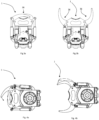
- Figure 3a shows a gripper system 1 from a top perspective wherein the master actuator 10 and slave actuator 12 are in a fully extended state and in a closed position 38.
- Figure 3b shows a gripper system 1 from a top perspective wherein the master and slave actuator 10, 12 are in a fully retracted state and in an open position 36.
- master and slave actuator chambers have been of the same size, resulting in the fluid volume released from the rod end chamber of the master actuator with each piston rod movement is lesser than the volume of pressurized fluid directed to its head end chamber. Consequently, the master actuator extends further and more rapidly than its slave counterpart.
- the master actuator 10 is larger than the slave actuator 12 by a fixed ratio, enabling the master and slave actuator 10, 12 to extend in a synchronized manner.
- the fixed ratio can be expressed as a function of the diameter of the master actuator chamber X, the master actuator piston Y, and the slave actuator chamber Z.
- Work implements design to grip or grab materials or objects occasionally experience synchronization failure due to other factors. This may include, for example: wear and tear; hydraulic issues; sensor malfunctions; software or control issues; electrical problems, such as faulty wiring; external factors, if for example one gripping component encounters more resistance than the other; calibration issues or lack of regular maintenance; extreme temperature that affect the performance of hydraulic fluids.
- the present invention enables for a gripping system 1 to either: synchronize the two gripping components 2, 4 in a closed position, as shown in figure 4a ; or synchronize the two gripping components 2, 4 in a open position, as shown in figure 4b .
- the proposed invention is capable of synchronize the two gripping components 2, 4 in a both closed position 38 and open position 38 by utilizing additional pressure relief valves.
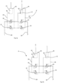
- Figure 5a schematically illustrates one proposed embodiment of a hydraulic arrangement in a scenario in which the master actuator 10 and the slave actuator 12 are in an extended state in the closed position 38 and wherein the slave actuator 12 is out of synchronization with the master actuator 10 in the closed position 38.
- the master actuator 10 which is coupled to the first gripping component 2 has a first master port 40 on a piston side and a second master port 42 on a rod side.
- the slave actuator 12, which is coupled to the second gripping component 4 has a first slave port 44 on a piston side and a second slave port 46 on a rod side.
- the hydraulic arrangement 8 comprises a first side 28 and a second side 30, in the illustrated scenario in figure 5a the first side 28 is connected to a hydraulic fluid pump and the second side 30 is connected to a hydraulic fluid tank, consequently the master actuator 10 and slave actuator 12 are moving towards a closed position 38.
- the gripper is moving towards an open position 36 the coupling is reversed, meaning that the first side 28 connects to the hydraulic tank and the second side 30 connects to the hydraulic pump.
- Hydraulic fluid moves through the hydraulic arrangement 8 via hydraulic conduits 26 which interconnects the various components in the system.
- the hydraulic arrangement 8 further comprises a first pressure relief valve 18 having a first relief pressure (p1) and a second pressure relief valve 20 having a second relief pressure (p2).
- the relief pressure valves 18, 19 can be any device or mechanism able to automatically open to release excess pressure when pressure exceeds a predetermined set point.
- the first relief pressure (p1) is smaller than the second relief pressure (p2).
- the master actuator 10 and the first pressure relief valve 18 are coupled in parallel via the hydraulic arrangement 8.
- the slave actuator 12 and the second pressure relief valve 20 are coupled in parallel via the hydraulic arrangement 8.
- the master actuator 10 and the first pressure relief valve 18 are coupled in series with the slave actuator 12 and the second pressure relief valve 20.
- first pressure relief valve 18 and the second pressure relief valve 20 are arranged to open up in a direction from the first side 28 to the second side 30 upon reaching the first pressure (p1) or the second pressure (p2) so that the first gripper component 2 or the second gripper component 4 can be moved into synchronization in a closed position 38.
- the pressure relief valves 18, 19 may be arranged to open up in the opposite direction, i.e from the second side 30 to the first side 30, which would enable the gripper component 2, 4 to be moved into synchronization in an open position 36.
- the master actuator 10 and the slave actuator 12 are in an extended state in the closed position 38 and the slave actuator 12 is out of synchronization with the master actuator 10.
- the dashed line with arrow indicate the conduit in which the hydraulic fluid moves to synchronize the actuators 10, 12.
- the hydraulic fluid flows from the first side 28, which is in this case the pump side, via the first pressure relief valve 18, which is in this case open since no more hydraulic fluid can be pumped into the master actuator 10 via the first master port 40 as the master actuator 10 is fully extended.
- the hydraulic fluid then moves towards the first slave port 44 for extending the slave actuator 12, which is illustrated by an arrow just above the piston on the slave actuator 12.
- the hydraulic fluid moves towards the second slave port 46 to the second side 30, which is connected to the hydraulic fluid tank.
- Figure 5b shows the same hydraulic arrangement 8 as illustrated in figure 5a but shows instead how the hydraulic fluid moves in a scenario in which the master actuator 10 is out of synchronization with the slave actuator 12. Following the dashed line it can be seen that the hydraulic fluid flows from the first side 28 via the first master port 40 into the master actuator 10 and from the second master port 42 to the second pressure relief valve 20.
- the second pressure relief valve 20 is in this case open since no more hydraulic fluid can be pumped into the slave actuator 12 via the first slave port 44 as the slave actuator 12 is fully extended. The fluid then moves from the second pressure relief valve 20 to the second side 30, which is connected to the hydraulic fluid tank.
- the master actuator 10 and the first pressure relief valve 18 are coupled in series with the first side 28; and the slave actuator 12 and the second pressure relief valve 20 are coupled in series with the second side 30.
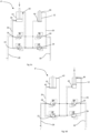
- Figure 6a schematically illustrates a hydraulic arrangement 8' wherein the hydraulic arrangement 8' comprises a third and fourth relief pressure valve 22, 24.
- the third pressure relief valve 22 have a third relief pressure (p3)
- the fourth pressure relief valve 24 have a fourth relief pressure (p4).
- the third relief pressure (p3) is smaller than the first relief pressure (p1).
- the third pressure relief valve 22 is coupled in parallel with the master actuator 10 and the first pressure relief valve 18.
- the fourth pressure relief valve 24 is coupled in parallel with the slave actuator 12 and the second pressure relief valve 20.
- the third pressure relief valve 22 and the fourth pressure relief valve 24 are designed to open in a direction from the second side 30 to the first side 28 and wherein the first pressure relief valve 18 and the second pressure relief valve 20 are designed to open in a direction from the first side 28 to the second side 30.
- the third and fourth pressure relief valve 22, 24 enable for the gripping components 2, 4 to be synchronized in both the open position 36 and the closed position 36.
- figure 6a and 6b it will be shown how the hydraulic fluid moves in a scenario in which the master and slave actuator 10, 12 are extended and out of synchronization. Wherein figure 6a show the slave actuator 12 out of synchronization and 6b show the master actuator 10 out of synchronization.
- figure 6c and 6d it will be shown how the hydraulic fluid moves in a scenario in which the master and slave actuator 10, 12 are retracted and out of synchronization. Wherein figure 6c show the master actuator 10 out of synchronization and 6d the slave actuator 12 out of synchronization.
- the illustrated embodiment depicts a scenario in which the master actuator 10 and the slave actuator 12 are in an extended state in the closed position 38 and the slave actuator 12 is out of synchronization with the master actuator 10.
- the dashed line with arrow indicate the conduit in which the hydraulic fluid moves to synchronize the actuators 10, 12.
- the hydraulic fluid flows from the first side 28, which is in this case the pump side, via the first pressure relief valve, which is in this case open since no more hydraulic fluid can be pumped into the master actuator 10 via the first master port 40 as the master actuator is fully extended.
- the hydraulic fluid then moves towards the first slave port 44 for extending the slave actuator 12, which is illustrated by an arrow just above the piston on the slave actuator 12.
- the hydraulic fluid moves towards the second slave port 46 to the second side 30, which is connected to the hydraulic fluid tank.
- Figure 6b shows the same hydraulic arrangement 8' as illustrated in figure 6a but shows instead how the hydraulic fluid moves in a scenario in which the master actuator 10 is out of synchronization with the slave actuator 12. Following the dashed line it can be seen that the hydraulic fluid flows from the first side 28 via the first master port 40 into the master actuator 10 and from the second master port 42 to the second pressure relief valve 20.
- the second pressure relief valve 20 is in this case open since no more hydraulic fluid can be pumped into the slave actuator 12 via the first slave port 44 as the slave actuator 12 is fully extended. The fluid then moves from the second pressure relief valve 20 to the second side 30, which is connected to the hydraulic fluid tank.
- Figure 6c and 6d shows the same hydraulic arrangement 8' as in figure 6a and 6b but shows a scenario in master and slave actuators 10, 12 are retracted.
- Figure 6c schematically illustrates a hydraulic arrangement 8' wherein the hydraulic arrangement 8' comprises a third and fourth relief pressure valve 22, 24 and wherein the master actuator 10 and the slave actuator 12 are in an retracted state in the open position 36 and wherein the master actuator 10 is out of synchronization with the slave actuator 12 in the open position 36.
- the hydraulic fluid flows from the second side 30, which is in this case the pump side, via the fourth pressure relief valve 24, which is in this case upon since no more hydraulic fluid can be pumped into the slave actuator 12 via the second slave port 46 as the slave actuator 12 is retracted.
- the fluid then moves towards the second master port 42 for retracting the master actuator 10 and then from the first master port 40 to the first side 28, which is connected to the hydraulic fluid tank.
- Figure 6d schematically illustrates the same hydraulic arrangement 8' as shown in figure 6c but shows a scenario in which the slave actuator 10 is out of synchronization with the master actuator 10 in the open position 36.
- a hydraulic fluid flows from the second side 30, which in this case is the pump side, to the second slave port 46 for retracting the slave actuator 12.
- the hydraulic fluid then moves from the first slave port 44 via the third pressure relief valve 22, which in this is case open since no more hydraulic fluid can be pumped into the master actuator 10 via the second master port 42 as the master actuator is fully retracted, to the first side 28, which is connected to the hydraulic fluid tank.
- the master actuator 10 the first pressure relief valve 18 and the third pressure relief valve 22 are coupled in series with the first side 28. While the slave actuator 12, the second pressure relief valve 20 and the fourth pressure relief valve 24 are coupled in series with the second side 30.
Landscapes
- Engineering & Computer Science (AREA)
- Mechanical Engineering (AREA)
- General Engineering & Computer Science (AREA)
- Mining & Mineral Resources (AREA)
- Civil Engineering (AREA)
- Structural Engineering (AREA)
- Physics & Mathematics (AREA)
- Fluid Mechanics (AREA)
- Robotics (AREA)
- Fluid-Pressure Circuits (AREA)
Priority Applications (3)
| Application Number | Priority Date | Filing Date | Title |
|---|---|---|---|
| EP23198622.5A EP4528037A1 (fr) | 2023-09-20 | 2023-09-20 | Outil de travail avec composants de préhension et agencement hydraulique |
| PCT/EP2024/075278 WO2025061531A1 (fr) | 2023-09-20 | 2024-09-10 | Système de préhension à agencement hydraulique |
| AU2024346296A AU2024346296A1 (en) | 2023-09-20 | 2024-09-10 | Gripper system with hydraulic arrangement |
Applications Claiming Priority (1)
| Application Number | Priority Date | Filing Date | Title |
|---|---|---|---|
| EP23198622.5A EP4528037A1 (fr) | 2023-09-20 | 2023-09-20 | Outil de travail avec composants de préhension et agencement hydraulique |
Publications (1)
| Publication Number | Publication Date |
|---|---|
| EP4528037A1 true EP4528037A1 (fr) | 2025-03-26 |
Family
ID=88098223
Family Applications (1)
| Application Number | Title | Priority Date | Filing Date |
|---|---|---|---|
| EP23198622.5A Pending EP4528037A1 (fr) | 2023-09-20 | 2023-09-20 | Outil de travail avec composants de préhension et agencement hydraulique |
Country Status (3)
| Country | Link |
|---|---|
| EP (1) | EP4528037A1 (fr) |
| AU (1) | AU2024346296A1 (fr) |
| WO (1) | WO2025061531A1 (fr) |
Cited By (1)
| Publication number | Priority date | Publication date | Assignee | Title |
|---|---|---|---|---|
| US20240391739A1 (en) * | 2023-05-22 | 2024-11-28 | Paladin Brands Group, Inc. | Grapple Assembly with Force Limiting Device and Method for Using |
Citations (4)
| Publication number | Priority date | Publication date | Assignee | Title |
|---|---|---|---|---|
| US5110251A (en) | 1989-01-17 | 1992-05-05 | Gray Ralph E | Hydraulic platform lift for truck trailers |
| US5682955A (en) | 1996-09-06 | 1997-11-04 | Caterpillar Inc. | Blade control system for an earthmoving blade |
| EP0995557A2 (fr) * | 1998-10-07 | 2000-04-26 | Cascade Corporation | Système adaptatif de saisie d'une charge |
| CN214527674U (zh) * | 2020-12-24 | 2021-10-29 | 恩倍力(昆山)机械有限公司 | 一种电动液压抓具在集装箱装卸设备中的操作系统 |
-
2023
- 2023-09-20 EP EP23198622.5A patent/EP4528037A1/fr active Pending
-
2024
- 2024-09-10 AU AU2024346296A patent/AU2024346296A1/en active Pending
- 2024-09-10 WO PCT/EP2024/075278 patent/WO2025061531A1/fr active Pending
Patent Citations (4)
| Publication number | Priority date | Publication date | Assignee | Title |
|---|---|---|---|---|
| US5110251A (en) | 1989-01-17 | 1992-05-05 | Gray Ralph E | Hydraulic platform lift for truck trailers |
| US5682955A (en) | 1996-09-06 | 1997-11-04 | Caterpillar Inc. | Blade control system for an earthmoving blade |
| EP0995557A2 (fr) * | 1998-10-07 | 2000-04-26 | Cascade Corporation | Système adaptatif de saisie d'une charge |
| CN214527674U (zh) * | 2020-12-24 | 2021-10-29 | 恩倍力(昆山)机械有限公司 | 一种电动液压抓具在集装箱装卸设备中的操作系统 |
Cited By (1)
| Publication number | Priority date | Publication date | Assignee | Title |
|---|---|---|---|---|
| US20240391739A1 (en) * | 2023-05-22 | 2024-11-28 | Paladin Brands Group, Inc. | Grapple Assembly with Force Limiting Device and Method for Using |
Also Published As
| Publication number | Publication date |
|---|---|
| WO2025061531A1 (fr) | 2025-03-27 |
| AU2024346296A1 (en) | 2026-03-26 |
Similar Documents
| Publication | Publication Date | Title |
|---|---|---|
| US9303632B2 (en) | Energy recovery control circuit and work machine | |
| EP2402513B1 (fr) | Machine de construction à double bras | |
| US20130008153A1 (en) | Tool coupler assembly | |
| EP2696081A1 (fr) | Entraînement hydraulique de machine | |
| US20150225920A1 (en) | Quick Coupler | |
| JP2013148175A (ja) | 建設機械の油圧回路 | |
| CN107386344B (zh) | 集成式挖掘机销抓取器快速联接器 | |
| KR102421042B1 (ko) | 작업 기계용 하중 감지 유압 시스템 및 하중 감지 유압 시스템을 제어하는 방법 | |
| EP4528037A1 (fr) | Outil de travail avec composants de préhension et agencement hydraulique | |
| JP5756853B2 (ja) | 作業機器の液圧可動式作業要素を作動させる方法及び作業機器 | |
| US7383681B2 (en) | Method and apparatus for coordinated linkage motion | |
| JPH11181819A (ja) | カプラの油圧保持装置 | |
| JP2010242774A (ja) | シリンダ制御装置および作業機械 | |
| KR20260056319A (ko) | 유압 장치를 갖춘 그리퍼 시스템 | |
| CN121986203A (en) | Gripper system with hydraulic device | |
| JPH07166571A (ja) | アタッチメント用カプラ | |
| CN104278703A (zh) | 挖掘机动臂减震液压控制装置 | |
| CN109356218B (zh) | 装载机用分配阀及装载机液压系统 | |
| EP1475345A1 (fr) | Procédé pour la commande d'une flèche de grue et dispositif pour la mise en oeuvre du procédé | |
| WO2004007338A1 (fr) | Dispositif de transmission d'energie dans un machine a usiner | |
| CN119266331B (zh) | 一种正铲挖掘机的平推装料液压控制系统、方法和正铲挖掘机 | |
| CN222121913U (zh) | 用于工程机械的液压系统和工程机械 | |
| EP4382675A1 (fr) | Engin de chantier | |
| CN215483242U (zh) | 方向控制阀、装载机液压系统和装载机 | |
| JPH05321301A (ja) | 建設機械の油圧回路 |
Legal Events
| Date | Code | Title | Description |
|---|---|---|---|
| PUAI | Public reference made under article 153(3) epc to a published international application that has entered the european phase |
Free format text: ORIGINAL CODE: 0009012 |
|
| STAA | Information on the status of an ep patent application or granted ep patent |
Free format text: STATUS: THE APPLICATION HAS BEEN PUBLISHED |
|
| AK | Designated contracting states |
Kind code of ref document: A1 Designated state(s): AL AT BE BG CH CY CZ DE DK EE ES FI FR GB GR HR HU IE IS IT LI LT LU LV MC ME MK MT NL NO PL PT RO RS SE SI SK SM TR |
|
| STAA | Information on the status of an ep patent application or granted ep patent |
Free format text: STATUS: REQUEST FOR EXAMINATION WAS MADE |
|
| 17P | Request for examination filed |
Effective date: 20250916 |