EP4528040A1 - Vorrichtung zur befestigung eines sanitären vakuum-abflussrohres an einem schaft, z.b. einer gewindestange - Google Patents
Vorrichtung zur befestigung eines sanitären vakuum-abflussrohres an einem schaft, z.b. einer gewindestange Download PDFInfo
- Publication number
- EP4528040A1 EP4528040A1 EP24190787.2A EP24190787A EP4528040A1 EP 4528040 A1 EP4528040 A1 EP 4528040A1 EP 24190787 A EP24190787 A EP 24190787A EP 4528040 A1 EP4528040 A1 EP 4528040A1
- Authority
- EP
- European Patent Office
- Prior art keywords
- shaped parts
- rod
- shaped
- pipe
- branches
- Prior art date
- Legal status (The legal status is an assumption and is not a legal conclusion. Google has not performed a legal analysis and makes no representation as to the accuracy of the status listed.)
- Pending
Links
Images


Classifications
-
- F—MECHANICAL ENGINEERING; LIGHTING; HEATING; WEAPONS; BLASTING
- F16—ENGINEERING ELEMENTS AND UNITS; GENERAL MEASURES FOR PRODUCING AND MAINTAINING EFFECTIVE FUNCTIONING OF MACHINES OR INSTALLATIONS; THERMAL INSULATION IN GENERAL
- F16L—PIPES; JOINTS OR FITTINGS FOR PIPES; SUPPORTS FOR PIPES, CABLES OR PROTECTIVE TUBING; MEANS FOR THERMAL INSULATION IN GENERAL
- F16L3/00—Supports for pipes, cables or protective tubing, e.g. hangers, holders, clamps, cleats, clips, brackets
- F16L3/08—Supports for pipes, cables or protective tubing, e.g. hangers, holders, clamps, cleats, clips, brackets substantially surrounding the pipe, cable or protective tubing
- F16L3/12—Supports for pipes, cables or protective tubing, e.g. hangers, holders, clamps, cleats, clips, brackets substantially surrounding the pipe, cable or protective tubing comprising a member substantially surrounding the pipe, cable or protective tubing
- F16L3/13—Supports for pipes, cables or protective tubing, e.g. hangers, holders, clamps, cleats, clips, brackets substantially surrounding the pipe, cable or protective tubing comprising a member substantially surrounding the pipe, cable or protective tubing and engaging it by snap action
-
- F—MECHANICAL ENGINEERING; LIGHTING; HEATING; WEAPONS; BLASTING
- F16—ENGINEERING ELEMENTS AND UNITS; GENERAL MEASURES FOR PRODUCING AND MAINTAINING EFFECTIVE FUNCTIONING OF MACHINES OR INSTALLATIONS; THERMAL INSULATION IN GENERAL
- F16B—DEVICES FOR FASTENING OR SECURING CONSTRUCTIONAL ELEMENTS OR MACHINE PARTS TOGETHER, e.g. NAILS, BOLTS, CIRCLIPS, CLAMPS, CLIPS OR WEDGES; JOINTS OR JOINTING
- F16B37/00—Nuts or like thread-engaging members
- F16B37/08—Quickly-detachable or mountable nuts, e.g. consisting of two or more parts; Nuts movable along the bolt after tilting the nut
- F16B37/0871—Quickly-detachable or mountable nuts, e.g. consisting of two or more parts; Nuts movable along the bolt after tilting the nut engaging the bolt laterally, i.e. without the need to engage the end of the bolt
- F16B37/0878—Quickly-detachable or mountable nuts, e.g. consisting of two or more parts; Nuts movable along the bolt after tilting the nut engaging the bolt laterally, i.e. without the need to engage the end of the bolt in one piece, e.g. C-shaped nuts
-
- F—MECHANICAL ENGINEERING; LIGHTING; HEATING; WEAPONS; BLASTING
- F16—ENGINEERING ELEMENTS AND UNITS; GENERAL MEASURES FOR PRODUCING AND MAINTAINING EFFECTIVE FUNCTIONING OF MACHINES OR INSTALLATIONS; THERMAL INSULATION IN GENERAL
- F16B—DEVICES FOR FASTENING OR SECURING CONSTRUCTIONAL ELEMENTS OR MACHINE PARTS TOGETHER, e.g. NAILS, BOLTS, CIRCLIPS, CLAMPS, CLIPS OR WEDGES; JOINTS OR JOINTING
- F16B7/00—Connections of rods or tubes, e.g. of non-circular section, mutually, including resilient connections
- F16B7/18—Connections of rods or tubes, e.g. of non-circular section, mutually, including resilient connections using screw-thread elements
-
- F—MECHANICAL ENGINEERING; LIGHTING; HEATING; WEAPONS; BLASTING
- F16—ENGINEERING ELEMENTS AND UNITS; GENERAL MEASURES FOR PRODUCING AND MAINTAINING EFFECTIVE FUNCTIONING OF MACHINES OR INSTALLATIONS; THERMAL INSULATION IN GENERAL
- F16L—PIPES; JOINTS OR FITTINGS FOR PIPES; SUPPORTS FOR PIPES, CABLES OR PROTECTIVE TUBING; MEANS FOR THERMAL INSULATION IN GENERAL
- F16L3/00—Supports for pipes, cables or protective tubing, e.g. hangers, holders, clamps, cleats, clips, brackets
- F16L3/08—Supports for pipes, cables or protective tubing, e.g. hangers, holders, clamps, cleats, clips, brackets substantially surrounding the pipe, cable or protective tubing
- F16L3/12—Supports for pipes, cables or protective tubing, e.g. hangers, holders, clamps, cleats, clips, brackets substantially surrounding the pipe, cable or protective tubing comprising a member substantially surrounding the pipe, cable or protective tubing
- F16L3/127—Supports for pipes, cables or protective tubing, e.g. hangers, holders, clamps, cleats, clips, brackets substantially surrounding the pipe, cable or protective tubing comprising a member substantially surrounding the pipe, cable or protective tubing and extending away from the attachment surface
-
- F—MECHANICAL ENGINEERING; LIGHTING; HEATING; WEAPONS; BLASTING
- F16—ENGINEERING ELEMENTS AND UNITS; GENERAL MEASURES FOR PRODUCING AND MAINTAINING EFFECTIVE FUNCTIONING OF MACHINES OR INSTALLATIONS; THERMAL INSULATION IN GENERAL
- F16L—PIPES; JOINTS OR FITTINGS FOR PIPES; SUPPORTS FOR PIPES, CABLES OR PROTECTIVE TUBING; MEANS FOR THERMAL INSULATION IN GENERAL
- F16L3/00—Supports for pipes, cables or protective tubing, e.g. hangers, holders, clamps, cleats, clips, brackets
- F16L3/26—Supports for pipes, cables or protective tubing, e.g. hangers, holders, clamps, cleats, clips, brackets specially adapted for supporting the pipes all along their length, e.g. pipe channels or ducts
Definitions
- the invention relates to the field of supplying equipment for plumbers, masons or other tradespeople, requiring the fixing of an evacuation pipe in a crawl space.
- the invention finds an advantageous application when it comes to fixing an evacuation pipe in a crawl space to a threaded rod under a slab or a false ceiling.
- Crawl space pipes require a specific slope for waste or wastewater drainage.
- hangers or metal rods
- These hangers, or metal rods must be cut to a specific and precise length in order to achieve a suitable slope. They are then fixed under the slab in ascending order of size. Finally, a suspension collar or clamp is attached to the lower end of these hangers or rods, to accommodate the pipe in the crawl space.
- One of the aims of the invention is therefore to remedy the problems of the prior art by providing a device for fixing a pipe in a crawl space which is of simple, modular design, while avoiding a multiplication of production steps which would increase installation costs.
- Another objective is to provide a sanitary pipe fixing device that is adaptable and precisely adjustable, without compromising the fixing structure as a whole.
- Another objective is to be able to ensure the stability of a sanitary pipe fixing device, avoiding the risks of wear or fracture of the pipe.
- a device for fixing a drain pipe in a crawl space to a threaded rod anchored under a slab or false ceiling.
- the device is made from a single piece, making it very simple to design and assemble.
- the fixing device comprises means for snapping the discharge pipe comprising two elastic branches defining a C-shape.
- C-shape is meant any open shape capable of enclosing the circumference of the pipe.
- a U-shape or polygonal shape could quite easily be imagined without departing from the scope of the invention.
- the fixing device comprises at least two first C-shaped parts, located on an external face of at least one branch, the two first C-shaped parts being coaxial and spaced from each other by a distance corresponding at least to the diameter of the rod, each first C-shaped part having a diameter and an opening adapted for the passage of the rod, the openings of the two first C-shaped parts being opposite each other in order to allow locking of the first C-shaped parts on the rod by a quarter-turn movement after engagement of the rod in the space between the two first C-shaped parts, and the axis of the C-shaped latching means being orthogonal to the axis of the first C-shaped parts.
- the snap-on means allow the installation of a drain pipe quickly, safely, simply and efficiently.
- the C-shapes allow the device to be fixed to a pre-installed metal rod, quickly, without the rod being cut to a particular size.
- the height adjustment of the fixing device is carried out by screwing/unscrewing the device along the rod.
- the threaded rods may be considered to arrange the threaded rods in a staggered pattern along the drain pipe.
- the C-shape of the snap-in means, thanks to the two elastic branches, allows the reception of the evacuation pipe and to adapt to different sizes of pipes without difficulty.
- the device comprises second C-shaped parts, similar to the first C-shaped parts, located on the other branch of the snap-fastening means, which have for example a different diameter than that of the first C-shaped parts, in order to adapt to different sizes of rods.
- At least one of the branches and preferably both branches, have an end curved inwards to come into contact with the pipe in order to firmly hold the pipe snapped in place, and to adapt to different sizes of pipes.
- the curved end(s) of the branches have a curved transverse edge. This curved edge makes it possible to maintain a single point of contact with the evacuation pipe, and to compensate for any misalignments of the devices along the pipe.
- the branch(es) comprise an external rib provided in the space defined between the first C-shaped parts and/or second C-shaped parts, in order to exert a bearing force on the metal rod to facilitate the screwing/unscrewing operations of the device on the threaded rod.
- the external rib is transverse to engage a thread of the rod when the latter is threaded, or longitudinal to exert pressure on said thread in order to facilitate the adjustment of the position of the device along the rod by screwing/unscrewing the device.
- the external rib is longitudinal and has a triangular section.
- the elastic branches have a curved internal surface to compensate for any misalignments of the devices along the pipe.
- the fixing device according to the invention represents a practical and effective solution for fixing pipes in sanitary evacuation.
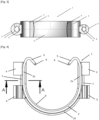
- the invention relates to a device (1) for fixing a drain pipe in a crawl space to a threaded rod anchored under a slab or false ceiling.
- the elastic branches are configured to receive a 100 mm diameter pipe in a snap-on manner, without this being limiting, which corresponds to the pipes commonly used for evacuation in crawl spaces.
- the device (1) also comprises two first C-shaped parts (3), located on an external face of the branches (2a), the two first C-shaped parts (3) being coaxial and spaced from each other by a distance corresponding at least to the diameter of the rod, for example preferably between 20 and 30 mm.
- Each first C-shaped part (3) has a diameter and an opening adapted for the passage of the rod, the openings of the two first C-shaped parts (3) being opposite each other in order to allow locking of the first C-shaped parts (3) on the rod by a movement of a quarter turn after engagement of the rod in the space between the two first C-shaped parts (3), the axis of the C-shaped latching means (2) being orthogonal to the axis of the first C-shaped parts.
- the invention allows, by snapping several devices onto threaded rods, to fix a pipe in a crawl space itself snapped between the two elastic branches (2a) of each device.
- the height adjustment of the fixing device in particular to ensure the recommended slope, is carried out by screwing/unscrewing the device along the rod.
- the handling is simple and effective.
- the devices are fixed to the threaded rods by positioning the elastic branches (2a) upwards to optimally support the pipe.
- a first device is positioned with the elastic branches (2a) facing downwards to be able to position the pipe as close as possible to the false ceiling if space is restricted.
- it can be considered to arrange the threaded rods in a staggered pattern along the drain pipe.
- the second C-shaped parts (4) are similar to the first C-shaped parts (3), and are located on the other branch (2a) of the snap-fitting means (2).
- the second C-shaped parts (4) have a different diameter than the first C-shaped parts (3), in order to adapt to different rod diameters used by craftsmen, for example M6, M7, M8 or M10.
- rod diameters used by craftsmen for example M6, M7, M8 or M10.
- one side can be M8 and the other M6/M7.
- the two branches (2a) have a curved end (5) towards the inside to come into contact with the pipe in order to firmly hold the pipe clipped, and to possibly adapt to different sizes of pipes.
- Each curved end (5) of the branches (2a), and in particular the free transverse edge, has a curved profile (6).
- This curved profile makes it possible to rest on the pipe at a point of contact and thus makes it possible to tolerate a misalignment of the devices along the pipe.
- Each branch (2a) of the snap-in means (2) comprises an external rib (7) provided in the space defined between the first C-shaped parts (3) and/or second C-shaped parts (4), in order to further secure the attachment with the threaded rod, by exerting a bearing force on the rod held in the first C-shaped parts (3) and the second C-shaped parts (4).
- each branch (2a) is for example longitudinal to exert pressure on said thread in order to allow the adjustment of the position of the device (1) along the rod by screwing/unscrewing the device (1).
- the rib (7) has a triangular section so that the tip of the triangle comes into linear support against the rod when engaged in the C shapes. This makes it possible to optimize the forces and the thread of the rod comes to dig and tap the tip of the rib.
- the first C-shaped parts (3) and the second C-shaped parts (4) comprise longitudinal internal ribs (8) provided on one face internal intended to exert pressure on the rod in order to ensure the immobilization of the device (1) and therefore its stability.
- the internal face (9) of the elastic branches (2a) and in particular their portion in contact with the pipe is curved in order to bear on the tube in a single line of contact to tolerate alignment defects of the devices along the pipe.
- the C-shaped snap-fastening means (2) of the discharge pipe comprise a rib (10) which runs along said C-shape to provide more rigidity.
- the device (1) for fixing a drain pipe in a crawl space offers a practical and effective solution for fixing drain pipes. Its one-piece design, its secure locking mechanism and its adaptability to different configurations of pipes and rods make it an easy-to-use device (1) for building and industry professionals.
Landscapes
- Engineering & Computer Science (AREA)
- General Engineering & Computer Science (AREA)
- Mechanical Engineering (AREA)
- Supports For Pipes And Cables (AREA)
Applications Claiming Priority (2)
| Application Number | Priority Date | Filing Date | Title |
|---|---|---|---|
| FR2310022A FR3153391B1 (fr) | 2023-09-21 | 2023-09-21 | Dispositif de fixation d’un tuyau d’évacuation en vide sanitaire à une tige, par exemple une tige filetée |
| FR2400376A FR3153390B1 (fr) | 2023-09-21 | 2024-01-15 | Dispositif de fixation d’un tuyau d’évacuation en vide sanitaire à une tige, par exemple une tige filetée |
Publications (1)
| Publication Number | Publication Date |
|---|---|
| EP4528040A1 true EP4528040A1 (de) | 2025-03-26 |
Family
ID=91960604
Family Applications (1)
| Application Number | Title | Priority Date | Filing Date |
|---|---|---|---|
| EP24190787.2A Pending EP4528040A1 (de) | 2023-09-21 | 2024-07-25 | Vorrichtung zur befestigung eines sanitären vakuum-abflussrohres an einem schaft, z.b. einer gewindestange |
Country Status (1)
| Country | Link |
|---|---|
| EP (1) | EP4528040A1 (de) |
Citations (7)
| Publication number | Priority date | Publication date | Assignee | Title |
|---|---|---|---|---|
| GB1315952A (en) * | 1969-09-09 | 1973-05-09 | Dom Holdings Ltd | Device for supporting a pipe cable or the like |
| GB2099289A (en) * | 1981-06-02 | 1982-12-08 | Ellis Patents Ltd | Pipe retaining clips |
| DE3131177A1 (de) * | 1981-08-06 | 1983-02-24 | Hans-Rainer 5800 Hagen Wichert | Schnellspannaufhaenger fuer ein rohr |
| US5351920A (en) | 1993-04-09 | 1994-10-04 | Pipe Tytes, Inc. | Pipe support |
| US6631876B1 (en) | 1997-08-28 | 2003-10-14 | Rapid Positioning Clips Limited | Plastic support devices especially for pipes and cables |
| US20040007648A1 (en) * | 2002-07-12 | 2004-01-15 | Nifco Inc. And Vtec Co., Ltd. | Clamp for holding elongated article |
| JP2005133783A (ja) * | 2003-10-29 | 2005-05-26 | Piolax Inc | クリップ |
-
2024
- 2024-07-25 EP EP24190787.2A patent/EP4528040A1/de active Pending
Patent Citations (7)
| Publication number | Priority date | Publication date | Assignee | Title |
|---|---|---|---|---|
| GB1315952A (en) * | 1969-09-09 | 1973-05-09 | Dom Holdings Ltd | Device for supporting a pipe cable or the like |
| GB2099289A (en) * | 1981-06-02 | 1982-12-08 | Ellis Patents Ltd | Pipe retaining clips |
| DE3131177A1 (de) * | 1981-08-06 | 1983-02-24 | Hans-Rainer 5800 Hagen Wichert | Schnellspannaufhaenger fuer ein rohr |
| US5351920A (en) | 1993-04-09 | 1994-10-04 | Pipe Tytes, Inc. | Pipe support |
| US6631876B1 (en) | 1997-08-28 | 2003-10-14 | Rapid Positioning Clips Limited | Plastic support devices especially for pipes and cables |
| US20040007648A1 (en) * | 2002-07-12 | 2004-01-15 | Nifco Inc. And Vtec Co., Ltd. | Clamp for holding elongated article |
| JP2005133783A (ja) * | 2003-10-29 | 2005-05-26 | Piolax Inc | クリップ |
Similar Documents
| Publication | Publication Date | Title |
|---|---|---|
| BE897584A (fr) | Raccord a fluide perfectionne | |
| FR3035428A3 (fr) | Systeme pour porte de douche, et porte de douche | |
| FR2719095A1 (fr) | Dispositif pour l'assemblage de bagues de roulements. | |
| FR2948434A1 (fr) | Dispositif et procede de raccordement d'une conduite a la traversee d'une paroi | |
| EP2525000A1 (de) | Device for attaching a pipe fitting to a wall | |
| EP0237688A1 (de) | Stützring für einen Schlauch | |
| EP2425170B1 (de) | System zur befestigung eines verbinders für ein fluidtransportrohr an einer wand | |
| EP2239394B1 (de) | Abstandshalter zur regulierbaren Beabstandung einer Tragschiene für Verkleidungselemente einer Fläche | |
| EP4528040A1 (de) | Vorrichtung zur befestigung eines sanitären vakuum-abflussrohres an einem schaft, z.b. einer gewindestange | |
| EP0833093A1 (de) | Vorrichtung zur dichten Stosskupplung von zwei Rohren aus Metall | |
| FR3153390A1 (fr) | Dispositif de fixation d’un tuyau d’évacuation en vide sanitaire à une tige, par exemple une tige filetée | |
| EP0524879B1 (de) | Befestigungsvorrichtung für wenigstens zwei aufeinanderliegende Teile | |
| EP1336763B1 (de) | Befestigungsmittel mit Klammer | |
| EP0020213B1 (de) | Verzweigungsanschluss einer Drainageleitung an eine Sammelleitung | |
| FR2974612A1 (fr) | Dispositif de fixation et de raccordement d'un organe d'alimentation d'appareil sanitaire sur une paroi et son procede de montage | |
| FR2590633A1 (fr) | Dispositif de fixation reglable, en particulier pour l'assemblage d'ecrans video | |
| FR3032510A1 (fr) | Embout d’evacuation d’eau ameliore | |
| EP0703372A1 (de) | Vorrichtung zum Handhaben und Positionieren von Schrauben | |
| EP4521010A1 (de) | Vorrichtung zum befestigen mindestens eines rohres an einem schaft, wie zum beispiel einem gewindestab oder einer stange eines stahlbetons | |
| EP3380681B1 (de) | Verankerungselement für ein sanitärbefestigungselement | |
| EP0219402B1 (de) | Schutz- und Isolierungseinheit für Gebäude | |
| EP3137693B1 (de) | Montagerahmen für toilette | |
| FR2896020A1 (fr) | Dispositif de fixation et de reglage d'une piece sur un support | |
| WO1998053214A1 (fr) | Dispositif de fixation d'un element a un support mince | |
| EP0525269B1 (de) | Abzweigeinrichtung zum Verbinden eines unabhängigen Abflusses mit einem Hauptnetz, hergestellt durch ein gewelltes Doppelwandrohr |
Legal Events
| Date | Code | Title | Description |
|---|---|---|---|
| PUAI | Public reference made under article 153(3) epc to a published international application that has entered the european phase |
Free format text: ORIGINAL CODE: 0009012 |
|
| STAA | Information on the status of an ep patent application or granted ep patent |
Free format text: STATUS: THE APPLICATION HAS BEEN PUBLISHED |
|
| AK | Designated contracting states |
Kind code of ref document: A1 Designated state(s): AL AT BE BG CH CY CZ DE DK EE ES FI FR GB GR HR HU IE IS IT LI LT LU LV MC ME MK MT NL NO PL PT RO RS SE SI SK SM TR |
|
| STAA | Information on the status of an ep patent application or granted ep patent |
Free format text: STATUS: REQUEST FOR EXAMINATION WAS MADE |
|
| 17P | Request for examination filed |
Effective date: 20250623 |
|
| STAA | Information on the status of an ep patent application or granted ep patent |
Free format text: STATUS: EXAMINATION IS IN PROGRESS |
|
| 17Q | First examination report despatched |
Effective date: 20260325 |