EP4528056A1 - Haltevorrichtung - Google Patents
Haltevorrichtung Download PDFInfo
- Publication number
- EP4528056A1 EP4528056A1 EP23199249.6A EP23199249A EP4528056A1 EP 4528056 A1 EP4528056 A1 EP 4528056A1 EP 23199249 A EP23199249 A EP 23199249A EP 4528056 A1 EP4528056 A1 EP 4528056A1
- Authority
- EP
- European Patent Office
- Prior art keywords
- holder
- hinge member
- hinge
- bearing portion
- bolt
- Prior art date
- Legal status (The legal status is an assumption and is not a legal conclusion. Google has not performed a legal analysis and makes no representation as to the accuracy of the status listed.)
- Pending
Links
Images

Classifications
-
- E—FIXED CONSTRUCTIONS
- E05—LOCKS; KEYS; WINDOW OR DOOR FITTINGS; SAFES
- E05D—HINGES OR SUSPENSION DEVICES FOR DOORS, WINDOWS OR WINGS
- E05D11/00—Additional features or accessories of hinges
- E05D11/10—Devices for preventing movement between relatively-movable hinge parts
- E05D11/1028—Devices for preventing movement between relatively-movable hinge parts for maintaining the hinge in two or more positions, e.g. intermediate or fully open
- E05D11/105—Devices for preventing movement between relatively-movable hinge parts for maintaining the hinge in two or more positions, e.g. intermediate or fully open the maintaining means acting perpendicularly to the pivot axis
- E05D11/1057—Devices for preventing movement between relatively-movable hinge parts for maintaining the hinge in two or more positions, e.g. intermediate or fully open the maintaining means acting perpendicularly to the pivot axis specially adapted for vehicles
-
- E—FIXED CONSTRUCTIONS
- E05—LOCKS; KEYS; WINDOW OR DOOR FITTINGS; SAFES
- E05D—HINGES OR SUSPENSION DEVICES FOR DOORS, WINDOWS OR WINGS
- E05D11/00—Additional features or accessories of hinges
- E05D11/10—Devices for preventing movement between relatively-movable hinge parts
- E05D11/1014—Devices for preventing movement between relatively-movable hinge parts for maintaining the hinge in only one position, e.g. closed
-
- E—FIXED CONSTRUCTIONS
- E05—LOCKS; KEYS; WINDOW OR DOOR FITTINGS; SAFES
- E05D—HINGES OR SUSPENSION DEVICES FOR DOORS, WINDOWS OR WINGS
- E05D3/00—Hinges with pins
- E05D3/02—Hinges with pins with one pin
-
- E—FIXED CONSTRUCTIONS
- E05—LOCKS; KEYS; WINDOW OR DOOR FITTINGS; SAFES
- E05D—HINGES OR SUSPENSION DEVICES FOR DOORS, WINDOWS OR WINGS
- E05D5/00—Construction of single parts, e.g. the parts for attachment
- E05D5/02—Parts for attachment, e.g. flaps
- E05D5/06—Bent flaps
- E05D5/062—Bent flaps specially adapted for vehicles
-
- E—FIXED CONSTRUCTIONS
- E05—LOCKS; KEYS; WINDOW OR DOOR FITTINGS; SAFES
- E05Y—INDEXING SCHEME ASSOCIATED WITH SUBCLASSES E05D AND E05F, RELATING TO CONSTRUCTION ELEMENTS, ELECTRIC CONTROL, POWER SUPPLY, POWER SIGNAL OR TRANSMISSION, USER INTERFACES, MOUNTING OR COUPLING, DETAILS, ACCESSORIES, AUXILIARY OPERATIONS NOT OTHERWISE PROVIDED FOR, APPLICATION THEREOF
- E05Y2201/00—Constructional elements; Accessories therefor
- E05Y2201/20—Brakes; Disengaging means; Holders; Stops; Valves; Accessories therefor
- E05Y2201/224—Stops
-
- E—FIXED CONSTRUCTIONS
- E05—LOCKS; KEYS; WINDOW OR DOOR FITTINGS; SAFES
- E05Y—INDEXING SCHEME ASSOCIATED WITH SUBCLASSES E05D AND E05F, RELATING TO CONSTRUCTION ELEMENTS, ELECTRIC CONTROL, POWER SUPPLY, POWER SIGNAL OR TRANSMISSION, USER INTERFACES, MOUNTING OR COUPLING, DETAILS, ACCESSORIES, AUXILIARY OPERATIONS NOT OTHERWISE PROVIDED FOR, APPLICATION THEREOF
- E05Y2201/00—Constructional elements; Accessories therefor
- E05Y2201/60—Suspension or transmission members; Accessories therefor
- E05Y2201/622—Suspension or transmission members elements
- E05Y2201/628—Bearings
-
- E—FIXED CONSTRUCTIONS
- E05—LOCKS; KEYS; WINDOW OR DOOR FITTINGS; SAFES
- E05Y—INDEXING SCHEME ASSOCIATED WITH SUBCLASSES E05D AND E05F, RELATING TO CONSTRUCTION ELEMENTS, ELECTRIC CONTROL, POWER SUPPLY, POWER SIGNAL OR TRANSMISSION, USER INTERFACES, MOUNTING OR COUPLING, DETAILS, ACCESSORIES, AUXILIARY OPERATIONS NOT OTHERWISE PROVIDED FOR, APPLICATION THEREOF
- E05Y2600/00—Mounting or coupling arrangements for elements provided for in this subclass
- E05Y2600/60—Mounting or coupling members; Accessories therefor
- E05Y2600/62—Bolts
-
- E—FIXED CONSTRUCTIONS
- E05—LOCKS; KEYS; WINDOW OR DOOR FITTINGS; SAFES
- E05Y—INDEXING SCHEME ASSOCIATED WITH SUBCLASSES E05D AND E05F, RELATING TO CONSTRUCTION ELEMENTS, ELECTRIC CONTROL, POWER SUPPLY, POWER SIGNAL OR TRANSMISSION, USER INTERFACES, MOUNTING OR COUPLING, DETAILS, ACCESSORIES, AUXILIARY OPERATIONS NOT OTHERWISE PROVIDED FOR, APPLICATION THEREOF
- E05Y2800/00—Details, accessories and auxiliary operations not otherwise provided for
- E05Y2800/26—Form or shape
- E05Y2800/266—Form or shape curved
-
- E—FIXED CONSTRUCTIONS
- E05—LOCKS; KEYS; WINDOW OR DOOR FITTINGS; SAFES
- E05Y—INDEXING SCHEME ASSOCIATED WITH SUBCLASSES E05D AND E05F, RELATING TO CONSTRUCTION ELEMENTS, ELECTRIC CONTROL, POWER SUPPLY, POWER SIGNAL OR TRANSMISSION, USER INTERFACES, MOUNTING OR COUPLING, DETAILS, ACCESSORIES, AUXILIARY OPERATIONS NOT OTHERWISE PROVIDED FOR, APPLICATION THEREOF
- E05Y2800/00—Details, accessories and auxiliary operations not otherwise provided for
- E05Y2800/26—Form or shape
- E05Y2800/292—Form or shape having apertures
- E05Y2800/296—Slots
-
- E—FIXED CONSTRUCTIONS
- E05—LOCKS; KEYS; WINDOW OR DOOR FITTINGS; SAFES
- E05Y—INDEXING SCHEME ASSOCIATED WITH SUBCLASSES E05D AND E05F, RELATING TO CONSTRUCTION ELEMENTS, ELECTRIC CONTROL, POWER SUPPLY, POWER SIGNAL OR TRANSMISSION, USER INTERFACES, MOUNTING OR COUPLING, DETAILS, ACCESSORIES, AUXILIARY OPERATIONS NOT OTHERWISE PROVIDED FOR, APPLICATION THEREOF
- E05Y2800/00—Details, accessories and auxiliary operations not otherwise provided for
- E05Y2800/26—Form or shape
- E05Y2800/33—Form or shape having protrusions
-
- E—FIXED CONSTRUCTIONS
- E05—LOCKS; KEYS; WINDOW OR DOOR FITTINGS; SAFES
- E05Y—INDEXING SCHEME ASSOCIATED WITH SUBCLASSES E05D AND E05F, RELATING TO CONSTRUCTION ELEMENTS, ELECTRIC CONTROL, POWER SUPPLY, POWER SIGNAL OR TRANSMISSION, USER INTERFACES, MOUNTING OR COUPLING, DETAILS, ACCESSORIES, AUXILIARY OPERATIONS NOT OTHERWISE PROVIDED FOR, APPLICATION THEREOF
- E05Y2800/00—Details, accessories and auxiliary operations not otherwise provided for
- E05Y2800/69—Permanence of use
- E05Y2800/694—Permanence of use during manufacturing
-
- E—FIXED CONSTRUCTIONS
- E05—LOCKS; KEYS; WINDOW OR DOOR FITTINGS; SAFES
- E05Y—INDEXING SCHEME ASSOCIATED WITH SUBCLASSES E05D AND E05F, RELATING TO CONSTRUCTION ELEMENTS, ELECTRIC CONTROL, POWER SUPPLY, POWER SIGNAL OR TRANSMISSION, USER INTERFACES, MOUNTING OR COUPLING, DETAILS, ACCESSORIES, AUXILIARY OPERATIONS NOT OTHERWISE PROVIDED FOR, APPLICATION THEREOF
- E05Y2900/00—Application of doors, windows, wings or fittings thereof
- E05Y2900/50—Application of doors, windows, wings or fittings thereof for vehicles
- E05Y2900/53—Type of wing
- E05Y2900/531—Doors
Definitions
- the invention relates to a retaining device according to the preamble of claim 1.
- the invention also relates to an automobile hinge according to the preamble of claim 9 and to a method according to the preamble of claim 12.
- an automobile body and automobile doors are typically painted together in a single process step after the automobile doors have been mounted on the body. It is desirable to lock automobile doors temporarily held in an open position so that specific painting work, e.g. a topcoat finish, can be performed.
- specific painting work e.g. a topcoat finish
- EP 1 561 890 A1 shows a retaining device for temporary connection to a hinge having an axis of rotation, comprising a holder assigned to a hinge member of the hinge, the holder comprising a curved elongate hole and an eye concentric to the axis of rotation, wherein the eye has a circumference for receiving a bolt defining the axis of rotation, wherein the holder is configured as an one-piece part detachable from the hinge and having a first side facing the hinge member, and wherein the holder comprises a folded portion, which can be inserted into a recess of an adjacent hinge member, so that this coupling generates an anti-rotation connection between the holder and the adjacent hinge member.
- this object is achieved by a retaining device having the features of claim 1 and accordingly by an automobile hinge having the features of claim 9 and by a method having the features of claim 12, respectively.
- a retaining device for a temporary connection to a hinge having an axis of rotation.
- the retaining device comprises a holder assigned to a hinge member of the hinge, the holder comprising a curved elongate hole and an eye concentric to the axis of rotation, wherein the eye has a circumference for receiving a bolt defining the axis of rotation, wherein the holder is configured as a one-piece part detachable from the hinge and having a first side facing the hinge member.
- the retaining device is characterized in that at least one projection extends from the first side, and that the at least one projection is arranged directly adjacent to the circumference of the eye.
- the at least one projection increases the friction between the hinge member and the holder, so that the holder is arranged at least frictionally on the hinge member, wherein the holder advantageously comprises an integrated anti-twist protection.
- the at least one projection has expediently a wall which at least partially axially prolongs a circumference of the eye.
- a contact surface between a bolt which can be inserted in the eye and the circumference of the eye is increased, so that a displacement of the holder about a horizontal axis is made more difficult.
- the holder has more than two projections, wherein the projections are arranged along a circle, wherein the projections are evenly spaced from each other, wherein the projections and the first side are arranged perpendicular to each other, and wherein the projections each have a height parallel to the axis of rotation of 0,1 mm to 1,0 mm, preferably of 0,2 mm to 0,6 mm and particularly preferably 0,5 mm.
- all projections have the same height so that the holder rests flat on the hinge member or on the counterpart.
- friction is advantageously increased by the presence of several projections so that the holder cannot perform any undesired displacement.
- the first side with the at least one projection is preferably configured, at least in sections, as a die stamp for deforming an at least mostly closed ring surface of an opposite material portion.
- the projections are suitable as a kind of embossing tool for pressing an impression into a mating part, which has a softer material than the holder, so that the holder is frictionally and form-fittingly locked in the mating part.
- the elongate hole has expediently at least one cross-sectional constriction, wherein at least one holding position is defined in the elongate hole, and wherein at least one breakthrough is arranged between the elongate hole and the eye.
- at least one stop position is defined via the constriction so that a vehicle door is held open in an open stop position during the painting process.
- the constriction is advantageously designed to be elastic via the breakthrough, so that the constriction is widened above a certain force and a stop pin can move further within the elongate hole, so that the vehicle door can be closed and opened again.
- the holder is configured as a flat corpus which has a second side opposite the first side, the second side facing away from the hinge member, wherein the first side and the second side are arranged parallel to one another, and that the first side and the second side are connected to one another at least in sections via an outer circumferential lateral area.
- the holder is advantageously flat and compact with a height of about 2 mm to 6 mm, wherein the holder has a low weight, and wherein the holder is stackable.
- the holder is preferably configured as a stamping made of sheet metal, in particular of a heat treatable steel.
- the holder is preferably made of a heat-treatable steel, e.g. C45E or 58CrV4, wherein the holder has a hardness between 56 and 62 HRC.
- the holder can be easily and economically manufactured using a stamping process, which saves time and costs.
- the retaining device is preferably provided during painting for fixing an automobile door in at least one preferred opening position.
- the holder is used for a painting process of an automobile body-in-white to hold a flap in a desired open position so that the body-in-white can be completely painted.
- the holder can advantageously be reused for further painting processes of further automobile bodies, so that costs can be saved.
- an automobile hinge comprises a first hinge member attachable to one of a body and a door of an automobile, and a second hinge member attachable to the other of the body and the door of said automobile, and a bolt which is connected to one of the first hinge member and the second hinge member in a rotationally fixed manner, wherein the other of said first hinge member and said second hinge member is pivotable about an axis of rotation defined by the bolt with respect to the one of said first hinge member and said second hinge member, wherein the other of said first hinge member and said second hinge member comprises at least one cantilever in which an opening is arranged, and wherein a stop pin is arranged on a surface of the cantilever.
- the automobile hinge is characterized by the retaining device according to one of the above-mentioned features, wherein the at least one projection is connected to one of the first hinge member and the second hinge member in a rotationally fixed manner, and the stop pin is accommodated in the elongate hole in a movable manner.
- the holder always remains in a defined position by means of this arrangement, so that a pin only moves within the elongate hole as soon as the automobile door is opened or closed. In this way, the pin and the holder can be used to provide a defined open position for the automobile door, which is necessary for the painting process.
- the one of said first hinge member and said second hinge member expediently has an axial bearing portion with a conical outside surface, and wherein the opening is configured as a conical opening which is complementary with respect to the conical outside surface and is connected in an articulated manner to the conical outside surface.
- the first hinge member and the second hinge member are advantageously connected to each other in an articulated manner.
- both hinge members have complementary cone-like connecting elements that advantageously simplify the assembly of the automobile door to the automobile body.
- the axial bearing portion with a conical outside surface preferably has a bore with, at least in sections, an internal thread, into which the bolt having an external thread is screwed in a manner such that a shaft of said bolt passes through the eye of the holder, and an area assigned to a head of said bolt extending radially beyond the eye couples in a rotationally fixed manner the at least one projection of the holder with the axial bearing portion.
- the holder is connected to the bearing portion by the bolt in a force-locking manner by means of surface pressure.
- the projections of the holder are pressed into the bearing portion so that the bearing portion is at least partially plastically deformed by the projections creating recesses in the bearing portion in which the projections are arranged, thus producing a form-fitting connection between the holder and the bearing portion.
- the holder is clamped in a sandwich-like manner between a head of the bolt or a washer and one hinge member, wherein this connection advantageously is a screw connection that can be easily loosened to remove the holder after the painting process.
- a method for temporarily connecting a retaining device to an automobile hinge comprises the steps of: Arranging an eye of a holder of the retaining device concentrically to a bore of a bearing portion of a hinge member of the automobile hinge; Inserting a bolt through the eye and the bore and connecting the bolt to the bearing portion in a detachable manner; and Applying a pre-adjustable force to the bolt to temporarily couple the holder to the bearing portion in a rotationally fixed manner.
- a simple attachment of the holder to the hinge is possible with an automobile door already mounted to an automobile body.
- the holder can advantageously be removed via the screw connection without disassembling the automobile door from the automobile body, thereby saving time and costs.
- the bore of the bearing portion advantageously has an internal thread
- the bolt has an external thread which is complementary with respect to the internal thread of the bore of the bearing portion
- the bolt is connectable to the bearing portion of the hinge member by applying a torque of between 10 Nm and 40 Nm, preferably between 15 Nm and 35 Nm and particularly preferably 30 Nm to the bolt.
- the bolt can simply be screwed in using a torque wrench with a defined tightening torque.
- the holder expediently comprises at least one projection which penetrates into at least a material portion of the bearing portion of the hinge member, and wherein the at least one material portion of the bearing portion is plastically deformed by the at least one projection of the holder.
- the holder is pressed together with the opposite hinge part so that the projections press into the soft material, creating a frictional and form-fitting connection between the holder and the hinge member.
- the holder is connected to the bearing portion by the bolt in a force-locking manner by means of surface pressure.
- the projections of the holder are pressed into the bearing portion so that the bearing portion is at least partially plastically deformed by the projections creating recesses in the bearing portion in which the projections are arranged, thus producing a form-fitting connection between the holder and the bearing portion.
- the Method preferably comprises a holder of a retaining device and/or an automobile hinge which are configured according to one of the above-mentioned features.
- this method is applicable by means of the retaining device according to the invention and the automobile hinge according to the invention.
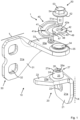
- Fig. 1 shows an exploded assembly view of an automobile hinge 10 with a retaining device 1 for a temporary connection to the automobile hinge 10.
- the automobile hinge 10 comprises a first hinge member 20 attachable to a body K of an automobile, and a second hinge member 30 attachable to a door T of the automobile, wherein both body K and door T are illustrated as a dashed line.
- the first hinge member 20 has a fastening portion 21 with a first plane 21a in which a mounting hole 22 is arranged for connecting the first hinge member 20 to the body K by means of riveting and/or screwing, for example. Furthermore, the first hinge member 20 comprises a cantilever 23 with a second plane 23a, wherein the first plane 21a of the fastening portion 21 is perpendicular to the second plane 23a of the cantilever 23.
- the first hinge member 20 further comprises an axial bearing portion 24 with a conical outside surface 25, wherein the bearing portion 24 is configured as a truncated cone, wherein the bearing portion 24 is arranged on the cantilever 23 of the first hinge member 20, and wherein the bearing portion 24 extends from the cantilever 23 of the first hinge member 20 in a direction away from the fastening portion 21 of the first hinge member 20.
- the bearing portion 24 has a material portion 27 with a ring surface 27a facing away from the cantilever 23 of the first hinge member 20. Furthermore, the ring surface 27a is arranged parallel to the second plane 23a.
- the bearing portion 24 further comprises along an axial axis a cylindrical bore 26 with an internal thread 26a for receiving a bolt 50 with a cylindrical shaft 51 with a complementary external thread 51a. Furthermore, the bolt has a tool appendix 54 which is configured as a hexagonal head.
- the second hinge member 30 has a fastening portion 31 with a first plane 31a in which two mounting holes 32 are arranged for connecting the second hinge member 30 to the door T by means of riveting and/or screwing, for example. Furthermore, the second hinge member 30 comprises a cantilever 33 with a second plane 33a, wherein the first plane 31a of the fastening portion 31 is perpendicular to the second plane 33a of the cantilever 33 of the second hinge member 30. Moreover, the cantilever 33 of the second hinge member 30 comprises an opening 34, which is configured as a conical opening 34a in which a conically shaped bushing 35 is arranged.
- the second hinge member 30 further comprises an axial cylindrical stop pin 60, wherein the stop pin 60 is arranged on the cantilever 33 of the second hinge member 30, and wherein the stop pin 60 extends from the cantilever 33 of the second hinge member 30 in a direction away from the second plane 33a of the cantilever 33 of the second hinge member 30.
- a holder 40 defining the retention device 1 having a lower first side 43 facing the hinge 10 and an opposite upper second side 44.
- the holder 40 is manufactured as a flat piece from a sheet of metal, wherein the holder 40 is produced by means of a stamping process, wherein the material of the holder 40 is a quenched and tempered steel of increased hardness.
- the first side 43 and the second side 44 are formed flat and parallel, wherein the first side 43 and the opposite second side 44 are joined together by an outer circumferential lateral area 48, wherein the lower first side 43 of the holder 40 faces the cantilever 33 of the hinge member 30.
- the holder 40 further comprises a cylindrical eye 42 having an inner circumference 42a, wherein the eye is surrounded by a flat material ring portion 49. Further, the holder 40 comprises a curved elongate hole 41 having a constriction 41a which is lockable with the stop pin 60, after which the stop pin 60 is slidably disposable in the elongate hole 41. A breakthrough 47 is arranged between the elongate hole 41 and the eye 42 so that the constriction 41a is elastically deformable. Moreover, the eye 42 has an inner diameter slightly larger than an outer diameter of the shaft 51 of the bolt 50.
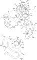
- Fig. 2 shows the exploded view of Fig. 1 from a bottom perspective, wherein the lower first side 43 of the holder 40 is visible, wherein three projections 45 are arranged offset from each other immediately adjacent to the eye 42 of the holder 40. Furthermore, a fixing portion 60a of the stop pin 60 is visible, wherein the stop pin 60 is riveted to the cantilever 33 of the second hinge member 30. Furthermore, a fixing portion 24a of the bearing portion 24 is visible, wherein the bearing portion 24 is riveted to the cantilever 23 of the first hinge member 20.
- Fig. 3 shows a bottom view of the lower first side 43 of the holder 40, wherein the arrangement of the three projections 45 is shown.
- the three projections 45 are arranged immediately adjacent to the inner circumference 42a of the eye 42, wherein one wall 45a of each of the projections 45 is configured to be flush with the circumference 42a and extends the circumference 42a in sections.
- the projections 45 are arranged along a concentric circle 46 with respect to the eye 42, wherein adjacent projections 45 enclose a common angle of ca. 120°.
- the concentric circle 46 is shown as a dashed line.
- the projections 45 have a substantially rectangular cross-sectional shape, wherein only the wall 45a of each projection 45 corresponding to the circumference 42a of the circle 46 is curved, and wherein edges of the projections 45 are each sharp-edged.
- a height of the projections 45 in this embodiment example is 0,5 mm, respectively, wherein the height of the projections 45 defines a length extending from the lower first side 43 in an outward direction. As a result, the lower first side 43 corresponds to a base surface of each of the projections 45.
- Fig. 4 shows a perspective view of the assembled automobile hinge 10 with the holder 40 attached to the first hinge member 20.
- the first hinge part 20 is rigidly connected to the body K of the automobile, with the holder 40 being pressed to the first hinge part 20 via the bolt 50 or via its area 52, so that the holder 40 and the first hinge part 20 are connected to each other in a rotationally fixed manner.
- the stop pin 60 in the elongate hole 41 of the holder 40 is displaced so that a maximum door opening is predetermined by the elongate hole 41 of the holder 40.
- the door T is held in an open position insofar as the pin 60 has passed the constriction 41a of the elongate hole 41 of the holder 40.
- the second hinge part 30 is pivotally connected to the first hinge part 20 as well as pivotally arranged with respect to the holder 40, wherein the elongate hole 41 of the holder 40 provides a defined opening angle of the door T by means of the stop pin 60.
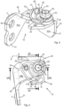
- Fig. 5 shows a top view of the assembled automobile hinge 10 of Fig. 4 with a first cut line VI-VI and a second cut line VII-VII.
- Fig. 6 shows a first sectional view VI-VI from Fig. 5 , showing the threaded connection between the bolt 50 and the bearing portion 24 with the conical outside surface 25 of the first hinge member 20. It can also be seen that one projection 45 of the holder 40 is pressed into a front side of the material portion 27 of the ring surface 27a of the bearing portion 24, providing a frictional and form-fitting connection between the holder 40 and the first hinge member 20. As a result, all projections 45 are uniformly pressed into the softer material portion 27 of the bearing portion 24 of the first hinge member 20 via the contact force of the area 52 of the bolt 50, thereby plastically deforming the bearing portion 24.
- the bushing 35 is arranged between the bearing portion 24 and the opening 34 of the second hinge part 30 to facilitate pivotal displacement of the second hinge member 30, wherein the bushing 35 is complementary with respect to the conical outside surface 25 of the bearing portion 24 of the first hinge member 20 and the conical opening 34a of the second hinge member 30. Furthermore, an axis of rotation A is clearly identifiable, about which the second hinge part 30 is rotatably displaceable.
- the holder 40 is arranged with its first side 43 spaced apart from the second hinge member 30 so that, when the second hinge member 30 is moved, no undesirable grinding and/or braking effect of the holder 40 with the cantilever 33 of the second hinge member 30 takes place, wherein a gap dimension 36 being approximately equal to a thickness of the bushing 35.
- the first hinge member 20 is also spaced apart from the second hinge member 30, the gap dimension 36 being approximately equal to a thickness of the bushing 35, so that during a pivoting of the second hinge member 30 no undesired braking effect occurs.
- Fig. 7 shows a second sectional view VII-VII from Fig. 5 , wherein the stop pin 60 is identifiable as being riveted with its fixing portion 60a to the cantilever 33 of the second hinge member 30, wherein the cantilever 33 has a bore hole 33b, in which the stop pin 60 is mounted. Furthermore, the stop pin 60 has a collar 60b which abuts the second plane 33a of the cantilever 33 of the second hinge member 30.
- the invention works as follows: First, the eye 42 of the holder 40 is arranged concentrically with respect to a bore 26 of the bearing portion 24 of the first hinge member 20, with projections 45 of the first side 43 of the holder 40 facing the bearing portion 24 and more specifically facing the ring surface 27a of the bearing portion 24. Then, the holder 40 is set on the bearing portion with the projections 45, with the stop pin 60 to be received in the elongate hole 41.
- a bolt 50 with an external thread 51a is inserted into the eye 42 and screwed into the bore 26 of the bearing portion 24.
- the screw connection is preferably made using a torque wrench, with a tightening torque of 30 Nm.
- the projections 45 of the holder 40 are pressed into the bearing portion 24 like an embossing die so that the bearing portion 24 is at least partially plastically deformed by the projections 45 creating recesses in the bearing portion 24 in which the projections 45 of the holder 40 are arranged, thus producing a form-fitting connection between the holder 40 and the bearing portion 24 of the first hinge member 20, so that the holder 40 is attached to the bearing portion 24 of the first hinge member 20 in a rotationally fixed manner with a non-slip traction.
- the bolt 50 is screwed in the opposite direction, e.g. with the aid of an open-end wrench, and removed from the bore 26 of the first hinge member 20 and from the eye 42 of the holder 40.
- the holder 40 can thus be removed immediately from the automobile hinge 10, with the bolt 50 again being inserted into the bore 26 of the first hinge member 20 and screwed to the first hinge member 20 and to the second hinge member 30, so that there is a completed automobile hinge 10, and wherein the holder 40 is reusable for further working processes, so that material and costs can be saved.
- the opposite bearing portion can be provided with complementary recesses in which projections and/or pins of the holder are insertable to provide a rotationally fixed connection between the holder and the bearing portion.
- a holder 40 comprises a cylindrical eye 42. It has to be understood that the eye of the holder can have sectional wrench flats, such as being formed as an internal hexagon, with the opposing bearing portion of the first hinge member having complementary wrench flats, such as being formed as an external hexagon, to provide a form-fit connection between the holder and the bearing portion.
- a holder 40 made from a heat-treatable steel via a stamping process It has to be understood that the holder 40 can be manufactured at least partially via a three-dimensional printing process.
- a threaded bolt 50 with a head 53 is used for a screw connection. It has to be understood that instead of the bolt a threaded rod can be used, which connects the holder and the first hinge member by means of a lower nut and an opposite upper nut, wherein the lower nut is assigned to the first hinge member and the upper nut is assigned to the holder, and wherein washers can be used.
- first hinge member 20 comprises a conical bearing portion 24. It has to be understood that the first hinge member and the second hinge member can be coupled to each other via a cylindrical hinge pin having a cylindrical collar. The collar of the hinge pin is arranged between the first hinge member and the second hinge member, wherein the hinge pin is riveted to one of the first hinge member and second hinge member.
- the hinge pin comprises an axial coupling section which extends beyond the first hinge member or beyond the second hinge member, wherein the coupling section comprises a bore with an internal thread, and wherein a holder is arrangeable on the coupling section, wherein an eye of the holder and the bore of the coupling section are arranged concentrically, and wherein a bolt is guided through the eye of the holder and into the bore to fasten the holder to the coupling section of the hinge pin with a defined tightening torque.
- projections of the holder press in a front face of the hinge pin to provide an anti-rotation connection of the holder with the hinge pin.
Landscapes
- Engineering & Computer Science (AREA)
- Mechanical Engineering (AREA)
- Hinges (AREA)
Priority Applications (3)
| Application Number | Priority Date | Filing Date | Title |
|---|---|---|---|
| EP23199249.6A EP4528056A1 (de) | 2023-09-22 | 2023-09-22 | Haltevorrichtung |
| US18/890,731 US20250101782A1 (en) | 2023-09-22 | 2024-09-19 | Retaining device |
| CN202411313845.6A CN119686597A (zh) | 2023-09-22 | 2024-09-20 | 定位装置 |
Applications Claiming Priority (1)
| Application Number | Priority Date | Filing Date | Title |
|---|---|---|---|
| EP23199249.6A EP4528056A1 (de) | 2023-09-22 | 2023-09-22 | Haltevorrichtung |
Publications (1)
| Publication Number | Publication Date |
|---|---|
| EP4528056A1 true EP4528056A1 (de) | 2025-03-26 |
Family
ID=88192046
Family Applications (1)
| Application Number | Title | Priority Date | Filing Date |
|---|---|---|---|
| EP23199249.6A Pending EP4528056A1 (de) | 2023-09-22 | 2023-09-22 | Haltevorrichtung |
Country Status (3)
| Country | Link |
|---|---|
| US (1) | US20250101782A1 (de) |
| EP (1) | EP4528056A1 (de) |
| CN (1) | CN119686597A (de) |
Families Citing this family (1)
| Publication number | Priority date | Publication date | Assignee | Title |
|---|---|---|---|---|
| EP4386162A1 (de) * | 2022-12-13 | 2024-06-19 | Collins Aerospace - Philippines | Scharniere |
Citations (3)
| Publication number | Priority date | Publication date | Assignee | Title |
|---|---|---|---|---|
| EP1561890A1 (de) | 2004-02-03 | 2005-08-10 | Edscha AG | Türfeststelleinrichtung |
| FR2916471A1 (fr) * | 2007-05-25 | 2008-11-28 | Coutier Moulage Gen Ind | Dispositif d'arret de porte provisoire pour porte de vehicule automobile. |
| EP4008869A1 (de) * | 2020-12-02 | 2022-06-08 | Defta | Feststellvorrichtung für ein fahrzeugscharnier |
-
2023
- 2023-09-22 EP EP23199249.6A patent/EP4528056A1/de active Pending
-
2024
- 2024-09-19 US US18/890,731 patent/US20250101782A1/en active Pending
- 2024-09-20 CN CN202411313845.6A patent/CN119686597A/zh active Pending
Patent Citations (3)
| Publication number | Priority date | Publication date | Assignee | Title |
|---|---|---|---|---|
| EP1561890A1 (de) | 2004-02-03 | 2005-08-10 | Edscha AG | Türfeststelleinrichtung |
| FR2916471A1 (fr) * | 2007-05-25 | 2008-11-28 | Coutier Moulage Gen Ind | Dispositif d'arret de porte provisoire pour porte de vehicule automobile. |
| EP4008869A1 (de) * | 2020-12-02 | 2022-06-08 | Defta | Feststellvorrichtung für ein fahrzeugscharnier |
Also Published As
| Publication number | Publication date |
|---|---|
| US20250101782A1 (en) | 2025-03-27 |
| CN119686597A (zh) | 2025-03-25 |
Similar Documents
| Publication | Publication Date | Title |
|---|---|---|
| US8601654B2 (en) | Door hinge repair apparatus and method | |
| US20250101782A1 (en) | Retaining device | |
| AU610273B2 (en) | Bush | |
| US20100024164A1 (en) | Lift-off door hinge | |
| EP1549457B1 (de) | Spannzange und Temporärbefestigungsvorrichtung | |
| US20040231467A1 (en) | Blind fastener and nose assembly for installation of the blind fastener | |
| JP2004508932A (ja) | スエージ型留めネジ差込用差込工具 | |
| US20040088844A1 (en) | Extractor, in particular for extracting center pins | |
| JP2002536607A (ja) | 機能ユニット用の支持装置 | |
| US5098238A (en) | Fastener with internal threaded installation means | |
| WO2005021214A1 (en) | Key and key holder for fastener installation tool | |
| US20110027040A1 (en) | Fastener assembly | |
| US6546610B2 (en) | Device for loosening a screw seated tightly in a mounting hole of a bearing eye or the like | |
| CA2495512A1 (en) | Pull type swage fasteners with removable mandrel | |
| CN115698456A (zh) | 具有集成式门限位件的汽车提离式铰链 | |
| MXPA05000993A (es) | Dispositivo rascador. | |
| AU2014238260A2 (en) | Systems and methods for improving bolted joints | |
| EP3628440B1 (de) | Positioniervorrichtung | |
| US4988031A (en) | Hand tool for installing and removing rivets | |
| US20160208534A1 (en) | Motor vehicle hinge | |
| BR102024018787A2 (pt) | Dispositivo de retenção | |
| US6234735B1 (en) | Spring-loaded compression and tension pin | |
| DE102008056407B4 (de) | Schließvorrichtung für Klappen | |
| DE202008007778U1 (de) | Kraftfahrzeugtürscharnier | |
| EP1844205B1 (de) | Montageschraube zur befestigung von beschlagteilen |
Legal Events
| Date | Code | Title | Description |
|---|---|---|---|
| PUAI | Public reference made under article 153(3) epc to a published international application that has entered the european phase |
Free format text: ORIGINAL CODE: 0009012 |
|
| STAA | Information on the status of an ep patent application or granted ep patent |
Free format text: STATUS: THE APPLICATION HAS BEEN PUBLISHED |
|
| AK | Designated contracting states |
Kind code of ref document: A1 Designated state(s): AL AT BE BG CH CY CZ DE DK EE ES FI FR GB GR HR HU IE IS IT LI LT LU LV MC ME MK MT NL NO PL PT RO RS SE SI SK SM TR |
|
| STAA | Information on the status of an ep patent application or granted ep patent |
Free format text: STATUS: REQUEST FOR EXAMINATION WAS MADE |
|
| 17P | Request for examination filed |
Effective date: 20250825 |