EP4528103A2 - Mécanisme de réglage électronique de débits dans une pompe à débit constant - Google Patents
Mécanisme de réglage électronique de débits dans une pompe à débit constant Download PDFInfo
- Publication number
- EP4528103A2 EP4528103A2 EP25156414.2A EP25156414A EP4528103A2 EP 4528103 A2 EP4528103 A2 EP 4528103A2 EP 25156414 A EP25156414 A EP 25156414A EP 4528103 A2 EP4528103 A2 EP 4528103A2
- Authority
- EP
- European Patent Office
- Prior art keywords
- motor
- pump
- base portion
- flange
- adjustment mechanism
- Prior art date
- Legal status (The legal status is an assumption and is not a legal conclusion. Google has not performed a legal analysis and makes no representation as to the accuracy of the status listed.)
- Pending
Links
Images


Classifications
-
- B—PERFORMING OPERATIONS; TRANSPORTING
- B01—PHYSICAL OR CHEMICAL PROCESSES OR APPARATUS IN GENERAL
- B01L—CHEMICAL OR PHYSICAL LABORATORY APPARATUS FOR GENERAL USE
- B01L3/00—Containers or dishes for laboratory use, e.g. laboratory glassware; Droppers
- B01L3/02—Burettes; Pipettes
- B01L3/0289—Apparatus for withdrawing or distributing predetermined quantities of fluid
- B01L3/0293—Apparatus for withdrawing or distributing predetermined quantities of fluid for liquids
-
- F—MECHANICAL ENGINEERING; LIGHTING; HEATING; WEAPONS; BLASTING
- F04—POSITIVE - DISPLACEMENT MACHINES FOR LIQUIDS; PUMPS FOR LIQUIDS OR ELASTIC FLUIDS
- F04B—POSITIVE-DISPLACEMENT MACHINES FOR LIQUIDS; PUMPS
- F04B1/00—Multi-cylinder machines or pumps characterised by number or arrangement of cylinders
- F04B1/12—Multi-cylinder machines or pumps characterised by number or arrangement of cylinders having cylinder axes coaxial with, or parallel or inclined to, main shaft axis
- F04B1/26—Control
- F04B1/28—Control of machines or pumps with stationary cylinders
- F04B1/29—Control of machines or pumps with stationary cylinders by varying the relative positions of a swash plate and a cylinder block
- F04B1/295—Control of machines or pumps with stationary cylinders by varying the relative positions of a swash plate and a cylinder block by changing the inclination of the swash plate
-
- F—MECHANICAL ENGINEERING; LIGHTING; HEATING; WEAPONS; BLASTING
- F04—POSITIVE - DISPLACEMENT MACHINES FOR LIQUIDS; PUMPS FOR LIQUIDS OR ELASTIC FLUIDS
- F04B—POSITIVE-DISPLACEMENT MACHINES FOR LIQUIDS; PUMPS
- F04B17/00—Pumps characterised by combination with, or adaptation to, specific driving engines or motors
- F04B17/03—Pumps characterised by combination with, or adaptation to, specific driving engines or motors driven by electric motors
-
- F—MECHANICAL ENGINEERING; LIGHTING; HEATING; WEAPONS; BLASTING
- F04—POSITIVE - DISPLACEMENT MACHINES FOR LIQUIDS; PUMPS FOR LIQUIDS OR ELASTIC FLUIDS
- F04B—POSITIVE-DISPLACEMENT MACHINES FOR LIQUIDS; PUMPS
- F04B49/00—Control, e.g. of pump delivery, or pump pressure of, or safety measures for, machines, pumps, or pumping installations, not otherwise provided for, or of interest apart from, groups F04B1/00 - F04B47/00
- F04B49/12—Control, e.g. of pump delivery, or pump pressure of, or safety measures for, machines, pumps, or pumping installations, not otherwise provided for, or of interest apart from, groups F04B1/00 - F04B47/00 by varying the length of stroke of the working members
- F04B49/123—Control, e.g. of pump delivery, or pump pressure of, or safety measures for, machines, pumps, or pumping installations, not otherwise provided for, or of interest apart from, groups F04B1/00 - F04B47/00 by varying the length of stroke of the working members by changing the eccentricity of one element relative to another element
- F04B49/128—Control, e.g. of pump delivery, or pump pressure of, or safety measures for, machines, pumps, or pumping installations, not otherwise provided for, or of interest apart from, groups F04B1/00 - F04B47/00 by varying the length of stroke of the working members by changing the eccentricity of one element relative to another element by changing the eccentricity of the cylinders, e.g. by moving a cylinder block
-
- F—MECHANICAL ENGINEERING; LIGHTING; HEATING; WEAPONS; BLASTING
- F04—POSITIVE - DISPLACEMENT MACHINES FOR LIQUIDS; PUMPS FOR LIQUIDS OR ELASTIC FLUIDS
- F04B—POSITIVE-DISPLACEMENT MACHINES FOR LIQUIDS; PUMPS
- F04B7/00—Piston machines or pumps characterised by having positively-driven valving
- F04B7/04—Piston machines or pumps characterised by having positively-driven valving in which the valving is performed by pistons and cylinders coacting to open and close intake or outlet ports
- F04B7/06—Piston machines or pumps characterised by having positively-driven valving in which the valving is performed by pistons and cylinders coacting to open and close intake or outlet ports the pistons and cylinders being relatively reciprocated and rotated
-
- F—MECHANICAL ENGINEERING; LIGHTING; HEATING; WEAPONS; BLASTING
- F04—POSITIVE - DISPLACEMENT MACHINES FOR LIQUIDS; PUMPS FOR LIQUIDS OR ELASTIC FLUIDS
- F04B—POSITIVE-DISPLACEMENT MACHINES FOR LIQUIDS; PUMPS
- F04B9/00—Piston machines or pumps characterised by the driving or driven means to or from their working members
- F04B9/02—Piston machines or pumps characterised by the driving or driven means to or from their working members the means being mechanical
-
- F—MECHANICAL ENGINEERING; LIGHTING; HEATING; WEAPONS; BLASTING
- F04—POSITIVE - DISPLACEMENT MACHINES FOR LIQUIDS; PUMPS FOR LIQUIDS OR ELASTIC FLUIDS
- F04B—POSITIVE-DISPLACEMENT MACHINES FOR LIQUIDS; PUMPS
- F04B13/00—Pumps specially modified to deliver fixed or variable measured quantities
-
- F—MECHANICAL ENGINEERING; LIGHTING; HEATING; WEAPONS; BLASTING
- F04—POSITIVE - DISPLACEMENT MACHINES FOR LIQUIDS; PUMPS FOR LIQUIDS OR ELASTIC FLUIDS
- F04B—POSITIVE-DISPLACEMENT MACHINES FOR LIQUIDS; PUMPS
- F04B19/00—Machines or pumps having pertinent characteristics not provided for in, or of interest apart from, groups F04B1/00 - F04B17/00
- F04B19/20—Other positive-displacement pumps
- F04B19/22—Other positive-displacement pumps of reciprocating-piston type
-
- F—MECHANICAL ENGINEERING; LIGHTING; HEATING; WEAPONS; BLASTING
- F04—POSITIVE - DISPLACEMENT MACHINES FOR LIQUIDS; PUMPS FOR LIQUIDS OR ELASTIC FLUIDS
- F04B—POSITIVE-DISPLACEMENT MACHINES FOR LIQUIDS; PUMPS
- F04B2203/00—Motor parameters
- F04B2203/04—Motor parameters of linear electric motors
-
- F—MECHANICAL ENGINEERING; LIGHTING; HEATING; WEAPONS; BLASTING
- F04—POSITIVE - DISPLACEMENT MACHINES FOR LIQUIDS; PUMPS FOR LIQUIDS OR ELASTIC FLUIDS
- F04B—POSITIVE-DISPLACEMENT MACHINES FOR LIQUIDS; PUMPS
- F04B49/00—Control, e.g. of pump delivery, or pump pressure of, or safety measures for, machines, pumps, or pumping installations, not otherwise provided for, or of interest apart from, groups F04B1/00 - F04B47/00
- F04B49/12—Control, e.g. of pump delivery, or pump pressure of, or safety measures for, machines, pumps, or pumping installations, not otherwise provided for, or of interest apart from, groups F04B1/00 - F04B47/00 by varying the length of stroke of the working members
- F04B49/123—Control, e.g. of pump delivery, or pump pressure of, or safety measures for, machines, pumps, or pumping installations, not otherwise provided for, or of interest apart from, groups F04B1/00 - F04B47/00 by varying the length of stroke of the working members by changing the eccentricity of one element relative to another element
- F04B49/125—Control, e.g. of pump delivery, or pump pressure of, or safety measures for, machines, pumps, or pumping installations, not otherwise provided for, or of interest apart from, groups F04B1/00 - F04B47/00 by varying the length of stroke of the working members by changing the eccentricity of one element relative to another element by changing the eccentricity of the actuation means, e.g. cams or cranks, relative to the driving means, e.g. driving shafts
Definitions
- the present invention relates to pumps used to dispense small amounts of fluids at accurate flow rates.
- the invention relates to a mechanism that electronically adjusts the dispensing of fluids from a pump at low flow rates.
- the invention relates to an angle adjustment mechanism for a pump and a motor.
- a family of valve-less pumps which have at their heart special mounting means, commonly referred to as a base, interposed between a drive motor and a pump head, is known in the art.
- These bases are typically injection molded plastic and incorporate a living hinge separating an upper base portion from a lower base portion.
- the upper base portion can be tilted with respect to the lower base portion by flexure of the living hinge.
- the relative angle between the upper and lower base portions establishes the pump output volume per revolution.
- the method for adjusting and setting the angle is accomplished by means of an adjusting screw engaging with pivot pins in the two portions of the base, which are positioned on the opposite side of the central axis of the base.
- Certain applications require pumps with the same target output per revolution.
- the fixed links are injection molded from plastic resin and the tooling used to mold these links allows for different lengths to be produced such that different target pump displacements can be routinely produced.
- An eccentric bushing providing a combination of the benefits of an adjusting screw and a fixed link is disclosed in commonly owned U.S. Patent Application Publication No. 2016/0245275 .
- U.S. Patent 7,708,535 discloses a method for electronic adjustment of the angle of the base.
- the device disclosed in this patent uses rigid members to translate linear motion to angular motion. This leads to varying angular movement relative to linear movement, which leads to a complex relationship when defining the linear motion required to adjust the angle between the two portions of the base.
- the output volume is not a constant flow rate when the motor is rotated at a constant speed.
- the flow rate through the pump head is sinusoidal with the dispense to the outlet port being the positive portion of the sine wave and the aspirate from the inlet port being the negative portion of the sine wave.
- a pump is used to aspirate a fluid into a probe tip and dispense portions of the aspirated fluid into other receptacles.
- a fixed displacement pump can be used for these cases by rotating the motor in the reverse direction to aspirate.
- the aspirate volume may not be the same as the calibrated dispense volume.
- a linear actuator is used to move the plunger to pull fluid into and push fluid out of a barrel.
- the accuracy of a syringe pump is generally tied to the size of the syringe barrel. The larger a syringe barrel, the lower its accuracy and precision. In order to have high accuracy at smaller volume dispenses or aspirates, a smaller barrel must be used. This is due to the smallest reliable increment of linear distance travelled in a syringe pump being related to a volume of fluid being moved. As the barrel size grows, this increment of linear distance relates to a larger volume of fluid being moved.
- Still another drawback with pumps of the prior art relates to the need for priming such pumps.
- some systems include a priming pump with a syringe pump.
- the priming pump fills the lines quicker than the syringe pump and also limits the use of the syringe pump in order to increase the time between required maintenance of the syringe pump.
- an electronic angle adjustment mechanism for a pump and a motor is provided.
- the mechanism generally includes a base, a linear actuator and a flexible member.
- the base has a motor flange for mounting a motor, a pump flange opposite the motor flange for mounting a pump and a hinge or hinge assembly disposed between the motor flange and the pump flange.
- the pump flange can be integrally formed as part of a collar that is attached to the pump housing or can be formed as part of the pump housing.
- the linear actuator is mounted to one of the motor flange or the pump flange of the base and the flexible member has a proximal end attached to the linear actuator and a distal end opposite the proximal end connected to the other of the motor flange or the pump flange of the base.
- the linear actuator drives the flexible member in a curved path causing the motor flange and the pump flange to pivot with respect to each other about the hinge, thereby changing an angle between the motor flange and the pump flange.
- the electronic angle adjustment mechanism can also include a cam block mounted to one of the motor flange or the pump flange, wherein the cam block has a curved support surface for guiding the flexible member in the curved path.
- An attachment plate can be mounted between the motor flange and the motor. The attachment plate extends outwardly from the motor parallel to the face of the motor flange and is sized to accommodate the mounting of the electronic adjustment mechanism.
- the attachment plate is integrally formed as part of the motor flange.
- the curved support surface has a radius of curvature about a pivot point of the base hinge defined by the distance from the pivot point to the connection point of the flexible member with the other of the motor flange or the pump flange.
- the angle adjustment mechanism preferably includes a roller bearing adjacent the cam block.
- the roller bearing presses the flexible member against the curved surface of the cam block.
- the flexible member may comprise a spring steel material such that the flexible member is bendable for transitioning a linear motion of the linear actuator to a pivoting motion of the motor flange and the pump flange with respect to one another.
- a motor and pump assembly in another aspect of the first embodiment, generally includes a base, a motor, a pump, a linear actuator and a flexible member.
- the base includes a motor flange, a pump flange opposite the motor flange and a hinge disposed between the motor flange and the pump flange.
- the motor is mounted to the motor flange of the base, and has a shaft rotatable about a rotation axis.
- the pump is mounted to the pump flange of the base, and has a piston rotatable about a rotation axis and linearly translatable along the rotation axis, wherein the pump piston is coupled to the motor shaft.
- the linear actuator is mounted to one of the motor flange or the pump flange of the base, and the flexible member has a proximal end attached to the linear actuator and a distal end opposite the proximal end connected to the other of the motor flange or the pump flange of the base.
- the linear actuator drives the flexible member in a curved path causing the motor flange and the pump flange to pivot with respect to each other about the hinge thereby changing an angle between the rotation axis of the motor shaft and the rotation axis of the pump piston about the hinge.
- the linear actuator includes a drive rod movable along a linear axis, and a drive rod coupler attached to a distal end of the drive rod, wherein the flexible member is attached to the drive rod coupler.
- the linear actuator is preferably mounted to the motor flange and the drive rod extends parallel with the rotation axis of the motor shaft.
- the linear actuator can be a DC, AC, or a brushless DC motor, more preferably a stepper motor.
- a method for adjusting the angular orientation between a motor shaft of a motor and a pump piston of a pump generally includes providing a base between the motor and the pump, wherein the base includes a motor flange for mounting the motor, a pump flange opposite the motor flange for mounting the pump and a hinge assembly disposed between the motor flange and the pump flange, and driving a flexible member in a curved path against one of the motor flange or the pump flange with a linear actuator mounted to the other of the motor flange or the pump flange, thereby changing an angle between the motor shaft and the pump piston about the hinge assembly.
- the pump and motor are the same as in the first embodiment described above.
- the base is formed by an upper base portion and a lower base portion that are pivotably connected by a hinge or hinge assembly but a different electronic adjustment mechanism is used.
- the attachment plate extends outwardly from the motor and a sidewall extends downwardly.
- An electric motor preferably a DC, AC, or brushless DC motor, more preferably a stepper motor, is attached to the outside of the sidewall and the motor shaft passes through the sidewall.
- a gear wheel with a plurality of teeth is attached to the distal end of the motor shaft.
- a collar is attached to the lower base portion.
- the collar fits around the outside of the lower base portion and is attached by a clamp, screws, bolts, an adhesive, or other known fastening devices.
- the collar can also be integrally formed as part of the lower base portion or pump housing and it can also have a flange extending outwardly from at least part of the exterior surface.
- the lower base portion is attached to the upper base portion by the hinge.
- a bracket having two parallel members with a slot in between extends outwardly from the collar.
- an arcuate member is attached between the two parallel members.
- the arcuate member curves inwardly towards the collar and has a concave surface with a plurality of teeth.
- the plurality of teeth on the gear wheel engage the plurality of teeth on the arcuate member and the motor controls the pivotal movement of the upper base portion in relation to the lower base portion.
- the pump and motor are the same as the first embodiment described above.
- the base is formed by an upper base portion and a lower base portion that are pivotably connected by a hinge or hinge assembly but a different electronic adjustment mechanism is used.
- the attachment plate extends outwardly from the motor and a sidewall extends downwardly.
- An electric motor preferably a DC, AC, or brushless DC motor, more preferably a stepper motor, is attached to the outside of the member and the motor shaft passes through the sidewall.
- a gear wheel with a plurality of teeth is attached to the distal end of the motor shaft.
- a collar as described above, is attached to the lower base portion.
- a bracket having two parallel members with a slot in between extends outwardly from the collar.
- an arcuate member is attached between the two parallel members.
- the arcuate member curves outwardly away from the collar and has a convex surface with a plurality of teeth.
- the plurality of teeth on the gear wheel engage the plurality of teeth on the arcuate member and the motor controls the pivotal movement of the upper base portion in relation to the lower base portion.
- the pump and motor are the same as the first embodiment described above.
- the base is formed by an upper base portion and a lower base portion that are pivotably connected by a hinge or hinge assembly but a different electronic adjustment mechanism is used.
- the attachment plate extends outwardly from the motor.
- a motor preferably a DC, AC, or brushless DC motor, more preferably a stepper motor, is mounted on the attachment plate with the motor shaft extending downwardly through the plate towards the pump.
- a worm screw is attached to the distal end of the motor shaft.
- a collar as described above, is attached to the lower base portion. One side of the collar is attached to the upper base portion by a hinge assembly.
- a bracket having two parallel members with a slot in between extends outwardly from the collar.
- an arcuate member is attached between the two parallel members.
- the arcuate member curves outwardly away from the collar and has a convex surface with a plurality of teeth.
- the plurality of teeth on the worm screw engage the plurality of teeth on the arcuate member and the motor controls the pivotal movement of the upper base portion in relation to the lower base portion.
- the invention utilizes a linear actuator to allow electronic adjustment of the angle between the pump piston and the motor shaft.
- the linear actuator is mounted to the upper base portion and adjustably connected to the lower base portion.
- the angle is adjustable electronically instead of manually.
- the pump can "syringe" fluid and dispense or aspirate at a near constant flow rate.
- the linear actuator When the linear actuator is extended, this will increase the angle between the portions of the base and the pump will aspirate through the active port.
- the linear actuator When the linear actuator is retracted, this will decrease the angle between the portions of the base and the pump will dispense through the active port.
- the angle can be manually or automatically adjusted to operate at one of several output volumes per revolution. For example, a large angle would be used for a high output volume per revolution for priming or flushing the fluid circuit. Then, the angle would be electronically adjusted to a small angle for a low output volume per revolution for small volume critical dispenses. With the ability to "syringe" fluid, a predictable and accurate aspirate and dispense volume can be achieved.
- this invention could be used like a traditional pump to prime the fluid circuit, and then operated like a syringe pump. This eliminates the need for two separate pumps and combines the syringe pump with the priming pump.
- FIG. 1 shows a conventional prior art motor 10 connected to a pump 12 via a base 14.
- the motor 10 has a shaft that rotates about a rotational axis and the pump has a piston that also rotates about a rotational axis and also translates in the direction of the rotational axis.
- the shaft of the motor is coupled to the piston of the pump so that rotation of the motor shaft will cause rotation of the pump piston. Also, by tilting the rotational axis of the pump piston with respect to the rotational axis of the motor shaft, rotation of the motor shaft will also cause linear translation of the pump piston in a manner that is described in further detail below.
- a pump and motor support arrangement of this type is shown and described in commonly owned U.S. Patent Nos. 4,941,809 and 5,020,980 , the specifications of which are incorporated herein by reference in their entirety for all purposes.
- FIG. 1 shows one prior art embodiment of an adjustable base 14, which includes a flange attached to the motor 10 and an opposing or mating flange attached to the pump 12. Between the two flanges is a flexible living hinge, which allows angular pivoting of the flanges with respect to the hinge. Opposite the hinge are two bosses, between which adjustable flow angle hardware is provided.
- the adjustable flow angle hardware is in the form of a screw and nut arrangement connected between pivot pins inserted in the respective bosses of the base. Rotation of the nut with respect to the screw selectively lengthens or shortens the length between the pivot pins of the bosses, thereby adjusting the angle of the motor flange with respect to the pump flange.
- FIG. 2 shows an alternative embodiment of a prior art motor/pump connection of the prior art utilizing a base, similar to the base shown in FIG. 1 , but utilizing a fixed link provided between the opposing bosses.
- the base 14 shown in FIG. 2 again includes a motor mounting flange and a pump mounting flange on opposite sides of a flexible living hinge. Opposite the hinge are opposed bosses between which a fixed link is provided to set the angle between the pump and the motor.
- the length of the fixed link is selected based on the desired volumetric flow produced by the pump. In certain applications, a variety of fixed links of differing lengths can be provided to adjust the volume of the pump in a predetermined range.
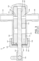
- the pump 12 generally includes a pump housing 101 and a piston 118.
- the pump housing 101 includes a plastic pump casing 102 having an inlet port 104 and an outlet port 106.
- the pump casing 102 defines a cylindrical chamber 108 having an open end 110.
- Received in the cylindrical chamber 108 is a ceramic piston liner 112 having a central longitudinal bore 114 and a transverse bore 116 communicating with the longitudinal bore 114.
- the transverse bore 116 includes a liner inlet port 116a fluidly communicating with the inlet port 104 of the pump casing 102 and a liner outlet port 116b fluidly communicating with the outlet port 106 of the pump casing so that a liquid can be pumped from the inlet port 116a, through the liner, to the outlet port 116b in a manner described below.
- the pump piston 118 is axially and rotatably slidable within the central bore 114 of the piston liner 112. One end of the piston 118 extends out of the open end 110 of the pump casing 102 and includes a coupling 120 for engagement with the shaft of the motor 10. At its opposite end, the piston 118 is formed with a relieved or "cutout" portion 122 disposed adjacent the transverse bore 116 of the pump liner. As described below, the relieved portion 122 is designed to direct fluid into and out of the pump 12.
- a seal assembly 124 is provided at the open end 110 of the pump casing 102 to seal the piston 118 and the pump chamber 108.
- the seal assembly 124 is retained at the open end 110 of the pump casing 102 by a gland nut 126 having a central opening 128 to receive the piston 118.
- the gland nut 126 is attached to the pump casing 102 with a threaded connection 130.
- the motor 10 drives the piston 118 to axially translate and rotate within the central bore 114 of the piston liner 112.
- the piston 118 is rotated as required to align the relieved portion 122 with the liner inlet port 116a.
- the piston 118 is then drawn back as required to take in the desired volume of liquid into the central bore 114 of the pump liner 112.
- Withdrawal of the piston 118 produces a negative pressure within the liner inlet port 116a of the transverse bore 116, which draws in liquid from the casing inlet port 104.
- the piston 118 is then rotated to align the relieved portion 122 with the liner outlet port 116b.
- the piston 118 is driven forward the required distance to force liquid into the outlet port 116b of the transverse bore 116 to produce the desired discharge flow.
- each rotation of the motor shaft rotates the piston of the pump. Due to the angular orientation between the pump and the motor, each rotation of the motor shaft further causes the pump piston to reciprocate in the axial direction to alternately draw in and push out fluid to transfer fluid between an inlet and an outlet of the pump.
- the amplitude of the piston stroke determines the volume of the fluid delivered between the inlet and the outlet of the pump.
- the angle of the pump 12 with respect to the motor 10 is adjustable via the base 14 to provide a desired volumetric flow of the pump with each rotation of the motor shaft. Therefore, it is desirable to provide a base 14 which is adapted for adjusting the angle between the axis of the pump and the motor shaft.
- a “stepper motor,” also known as step motor or stepping motor, is an electric motor that divides a full shaft rotation into a number of steps of essentially uniform magnitude when driven from a sequentially switched DC power supply.
- worm drive is a gear arrangement in which a worm or worm screw meshes with an arcuate (i.e., curved) member with a plurality of teeth.
- the worm screw and arcuate member are arranged in parallel along their longitudinal axes and the threads of the worm screw engage the teeth of the arcuate member. Rotation of the worm screw in a clockwise direction causes the arcuate member to move in a first direction and rotation of the worm screw in a counterclockwise direction causes the arcuate member to move in the opposite direction.
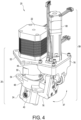
- the adjustable pump and motor assembly 20 includes a conventional motor 22 connected to a fixed displacement pump 24 (as described above with reference to FIG. 3 ) via a base 26 with a pivotably connected upper base portion 46 and a lower base portion 48.
- the motor 22 has a shaft 28 that is connected to a spindle coupling 32 and the shaft 28 rotates the spindle coupling 32 about a rotational axis.
- the pump 24 has a piston 30 that also rotates about a rotational axis and also translates in the direction of its rotational axis. One end of the piston 30 is connected to the spindle coupling 32.
- the shaft 28 of the motor 22 is coupled to the piston 30 of the pump 24 via the spindle coupling 32 so that rotation of the motor shaft 28 will cause rotation of the pump piston 30. Also, by tilting the rotational axis of the pump piston 30 with respect to the rotational axis of the motor shaft 28, rotation of the motor shaft 28 will also cause linear translation of the pump piston 30 and increase or decrease the volume of the chamber 35 at the distal end of the piston 30.
- the spherical bearing 36 rotates in the hollow of the spindle coupling 32.
- the reciprocal rotation of the pump piston 30 over a 180-degree arc switches the piston flat 44 between a first position facing the first port 40 and a second position facing the second port 42. In the first position, the piston flat 44 allows fluid to flow from the first port 40 into the chamber 35.
- the first port 40 is closed off and the piston flat 44 moves to the second position and dispenses the fluid from the chamber 35 through the second port 42.
- the piston flat 44 is open to only one port 40, 42 at a time.
- the angle between the axis of the pump piston 30 and the motor shaft 28 is determined by means of the base 26 having an upper base portion 46 and a lower base portion 48 pivotably connected to one another via a hinge 50.
- the upper base portion 46 has a flange 52 that attaches to the motor 22, and the lower base portion 48 has a flange 54 that holds the pump head 24 that houses the piston 30 and cylinder 38.
- the hinge 50 allows the upper base portion 46 to be tilted relative to the lower base portion 48 in a direction indicated by arrow 47 in FIG. 4 .
- the base 26, including the upper base portion 46 and lower base portion 48 are injection molded together with a living hinge 50. However, it is within the scope for these portions to be molded separately with a pinned hinge instead.
- the linear actuator 60 is preferably an electronic device capable of translating a linear actuator drive rod 62 in precise increments along a linear axis 64 extending parallel to the rotational axis of the motor shaft 28.
- One type of linear actuator for use is known in the art as a captive nut linear actuator.
- the motor flange 52 on the upper base portion 46 is preferably attached to the motor 22 by an attachment plate 66.
- the attachment plate 66 extends outwardly from the motor 22 and is sized and shaped to allow mounting of the linear actuator 60 of the electronic angle adjustment mechanism 59 to an upper surface 68 of the attachment plate 66.
- the mounting of the linear actuator 60 and the motor 22 on the upper surface 68 of the attachment plate 66 and mounting of the motor flange 52 on a lower surface 70 of the attachment plate 66 can be accomplished with conventional fasteners, such as bolts with threaded connections in respective components.
- the attachment plate 66 extends outwardly from the motor 22 and is formed from a single sheet of metal and shaped to accommodate the electronic angle adjustment mechanism 59.
- the flexible member 74 is preferably made from a material having the strength to transfer the linear force imparted by the drive rod 62 along its longitudinal axis 64, yet flexible enough to allow for some slight bending, as will be discussed further below.
- a suitable material for the flexible member for example, is spring steel.
- the flexible member 74 has a first end attached to the distal end of the drive rod coupler and a second end, opposite the first end, connected to the lower flange 54 of the base 26.
- linear motion of the linear actuator drive rod 62 will cause linear motion of the flexible member 74 in the same direction.
- linear actuator 60 is connected to the upper base portion 46 and the flexible member 74 is connected to the lower base portion 48, linear motion of the flexible member 74 will cause the lower base portion 48 to pivot with respect to the upper base portion 26 about the hinge 50.
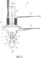
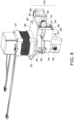
- FIG. 8 A third embodiment of the electronic adjustment mechanism 359 which is an embodiment of the present invention is shown in FIG. 8 .
- the attachment plate 366 is mounted between the motor 322 and a motor flange 352 on an upper base portion 346 and extends outwardly on one side of the motor 322.
- the upper base portion 346 and a lower base portion 348 connected to the pump 324 are pivotably connected by a hinge 350.
- a sidewall 368 on one side of the attachment plate 366 extends downwardly from the motor 322 towards the pump 324.
- An electric motor 360 is attached to the outside of the sidewall 368 and the motor shaft 362 passes through the sidewall 368.
- a gear wheel 374 with a plurality of teeth 376 is attached to the distal end of the motor shaft 362.
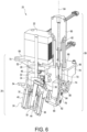
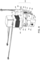
- a collar 454 is attached to the lower base portion 448 and one side of the collar 454 is attached to the upper base portion 446 by a hinge 450.
- a bracket 478 having two parallel members 480, 482 extends outwardly from the collar 454.
- an arcuate member 484 is attached between the two parallel members 480, 482.
- the arcuate member 484 curves outwardly away from the collar 454 and has a plurality of teeth 486 on the convex, outward surface.
- the continuous spiral thread 476 on the worm screw 474 engages the plurality of teeth 486 on the arcuate member 484 and the motor 460 controls the pivotal movement of the upper base portion 446 in relation to the lower base portion 448.
- Embodiments of the present invention embrace one or more computer readable media, wherein each medium may be configured to include or includes thereon data or computer executable instructions for manipulating data.
- the computer executable instructions include data structures, objects, programs, routines, or other program modules that may be accessed by a processing system, such as one associated with a general-purpose computer capable of performing various different functions or one associated with a special-purpose computer capable of performing a limited number of functions.
- Computer executable instructions cause the processing system to perform a particular function or group of functions and are examples of program code means for implementing steps for methods disclosed herein.
- a particular sequence of the executable instructions provides an example of corresponding acts that may be used to implement such steps.
- Examples of computer readable media include random-access memory (“RAM”), read-only memory (“ROM”), programmable read-only memory (“PROM”), erasable programmable read-only memory (“EPROM”), electrically erasable programmable read-only memory (“EEPROM”), compact disk read-only memory (“CD-ROM”), or any other device or component that is capable of providing data or executable instructions that may be accessed by a processing system.
- RAM random-access memory
- ROM read-only memory
- PROM programmable read-only memory
- EPROM erasable programmable read-only memory
- EEPROM electrically erasable programmable read-only memory
- CD-ROM compact disk read-only memory
- the computer device may be a personal computer, a notebook computer, a personal digital assistant ("PDA") or other hand-held device, a workstation, a minicomputer, a mainframe, a supercomputer, a multi-processor system, a network computer, a controller, a processor-based consumer electronic device, or the like.
- PDA personal digital assistant
- a mechanism for remote adjustment of the output volume per revolution of a fixed displacement pump is provided.
- the linear actuator By extending the linear actuator, the angle and output volume per revolution of the pump is increased.
- the linear actuator By retracting the linear actuator, the angle and output volume per revolution of the pump is decreased.
- the ability for electronic adjustment of flow allows the fixed displacement pump to utilize a large output volume per revolution to prime the lines, and then switch to a low output volume per revolution for the required small volume dispenses without manual intervention.
- the present invention further overcome issues of varying aspirate volumes relative to dispense volumes in a fixed displacement pump.
- these pumps have only been used to move fluid by rotation of the main motor.
- With the ability to electronically adjust the angle of the base a new method to move fluid with a syringing motion becomes possible.
- With the piston flat open to one port extending the linear actuator increases the angle of the base and pulls fluid into the pump head.
- the angle of the base decreases and pushes fluid out of the pump head.
- the linear motion has a proportional relation to the angular motion, which in turn has a proportional relation to the output volume. This extension and retraction gives a predictable aspirate and dispense volume from the active port.
- variable displacement pump can prime the lines by operating like a traditional fixed displacement pump and give constant flow rate dispenses by operating like a traditional syringe pump.
Landscapes
- Engineering & Computer Science (AREA)
- Mechanical Engineering (AREA)
- General Engineering & Computer Science (AREA)
- Chemical & Material Sciences (AREA)
- Analytical Chemistry (AREA)
- Health & Medical Sciences (AREA)
- Clinical Laboratory Science (AREA)
- Chemical Kinetics & Catalysis (AREA)
- Reciprocating Pumps (AREA)
- Transmission Devices (AREA)
Applications Claiming Priority (3)
| Application Number | Priority Date | Filing Date | Title |
|---|---|---|---|
| US201962881086P | 2019-07-31 | 2019-07-31 | |
| PCT/US2020/044252 WO2021022034A1 (fr) | 2019-07-31 | 2020-07-30 | Mécanisme de réglage électronique de débits dans une pompe à débit constant |
| EP20848262.0A EP4003597B1 (fr) | 2019-07-31 | 2020-07-30 | Mécanisme de réglage électronique de débits dans une pompe à débit constant |
Related Parent Applications (2)
| Application Number | Title | Priority Date | Filing Date |
|---|---|---|---|
| EP20848262.0A Division EP4003597B1 (fr) | 2019-07-31 | 2020-07-30 | Mécanisme de réglage électronique de débits dans une pompe à débit constant |
| EP20848262.0A Division-Into EP4003597B1 (fr) | 2019-07-31 | 2020-07-30 | Mécanisme de réglage électronique de débits dans une pompe à débit constant |
Publications (2)
| Publication Number | Publication Date |
|---|---|
| EP4528103A2 true EP4528103A2 (fr) | 2025-03-26 |
| EP4528103A3 EP4528103A3 (fr) | 2025-05-07 |
Family
ID=74229812
Family Applications (3)
| Application Number | Title | Priority Date | Filing Date |
|---|---|---|---|
| EP25156415.9A Pending EP4528104A3 (fr) | 2019-07-31 | 2020-07-30 | Mécanisme de réglage électronique de débits dans une pompe à débit constant |
| EP25156414.2A Pending EP4528103A3 (fr) | 2019-07-31 | 2020-07-30 | Mécanisme de réglage électronique de débits dans une pompe à débit constant |
| EP20848262.0A Active EP4003597B1 (fr) | 2019-07-31 | 2020-07-30 | Mécanisme de réglage électronique de débits dans une pompe à débit constant |
Family Applications Before (1)
| Application Number | Title | Priority Date | Filing Date |
|---|---|---|---|
| EP25156415.9A Pending EP4528104A3 (fr) | 2019-07-31 | 2020-07-30 | Mécanisme de réglage électronique de débits dans une pompe à débit constant |
Family Applications After (1)
| Application Number | Title | Priority Date | Filing Date |
|---|---|---|---|
| EP20848262.0A Active EP4003597B1 (fr) | 2019-07-31 | 2020-07-30 | Mécanisme de réglage électronique de débits dans une pompe à débit constant |
Country Status (7)
| Country | Link |
|---|---|
| US (4) | US12066015B2 (fr) |
| EP (3) | EP4528104A3 (fr) |
| JP (1) | JP7544809B2 (fr) |
| KR (1) | KR102878487B1 (fr) |
| CN (1) | CN114206503B (fr) |
| CA (1) | CA3148925A1 (fr) |
| WO (1) | WO2021022034A1 (fr) |
Families Citing this family (3)
| Publication number | Priority date | Publication date | Assignee | Title |
|---|---|---|---|---|
| CN112922820A (zh) * | 2021-03-26 | 2021-06-08 | 深圳市恒永达科技有限公司 | 一种可微调冲程的无阀柱塞泵 |
| JP7729977B2 (ja) * | 2021-08-20 | 2025-08-26 | フルード・メタリング・インコーポレイテッド | 較正可能な可変容量型ポンプ |
| CN117469122B (zh) * | 2022-07-20 | 2025-10-10 | 广东超流精密科技有限公司 | 一种双头注液泵 |
Citations (4)
| Publication number | Priority date | Publication date | Assignee | Title |
|---|---|---|---|---|
| US4941809A (en) | 1986-02-13 | 1990-07-17 | Pinkerton Harry E | Valveless positive displacement metering pump |
| US5020980A (en) | 1990-01-05 | 1991-06-04 | Dennis Pinkerton | Valveless, positive displacement pump including hinge for angular adjustment |
| US7708535B2 (en) | 2003-05-20 | 2010-05-04 | Zaxis, Inc. | Systems and methods for providing a dynamically adjustable reciprocating fluid dispenser |
| US20160245275A1 (en) | 2013-12-13 | 2016-08-25 | Fluid Metering, Inc. | Mechanism for Fine Adjustment of Flows in Fixed Displacement Pump |
Family Cites Families (20)
| Publication number | Priority date | Publication date | Assignee | Title |
|---|---|---|---|---|
| BE671597A (fr) * | 1964-11-05 | 1966-04-29 | ||
| US3382812A (en) | 1966-09-27 | 1968-05-14 | Gorman Rupp Ind Inc | Variable positive displacement pump |
| US5246354A (en) * | 1991-01-31 | 1993-09-21 | Abbott Laboratories | Valveless metering pump with reciprocating, rotating piston |
| US5158441A (en) * | 1991-04-15 | 1992-10-27 | Baxter International Inc. | Proportioning pump |
| US6398513B1 (en) * | 2000-09-20 | 2002-06-04 | Fluid Management, Inc. | Fluid dispensers |
| US7281375B1 (en) * | 2002-11-07 | 2007-10-16 | Hydro-Gear Limited Partnership | System and method for electronic actuation of axle driving apparatus |
| EA010848B1 (ru) * | 2004-10-20 | 2008-12-30 | Маркус Либхерр Интернациональ Аг | Гидростатическая аксиально-поршневая машина и применение такой машины |
| CA2569194C (fr) * | 2006-11-29 | 2014-01-14 | Gotohti.Com Inc. | Ensemble translateur de mouvement courbe en mouvement lineaire |
| CN102155375A (zh) * | 2011-05-06 | 2011-08-17 | 镇江宝城注浆设备有限公司 | 恒功率可调双液无级配比同步注浆泵 |
| US9849252B2 (en) * | 2012-05-04 | 2017-12-26 | Sofia Eleni Armes | Electromechanical manipulating device for medical needle and syringe with sensory biofeedback and pain suppression capability |
| GB201212155D0 (en) * | 2012-07-09 | 2012-08-22 | Stratec Biomedical Ag | A device and method for uptake or release of a liquid |
| EP2888475B1 (fr) * | 2012-07-30 | 2016-09-14 | Parker Hannifin Corporation | Système et procédé de contrôle de pompe |
| HU229852B1 (en) * | 2012-08-15 | 2014-10-28 | Hibar Systems Ltd Richmond Hill | Electronically controlled and driven linear pump actuator |
| CN203488325U (zh) * | 2013-10-24 | 2014-03-19 | 徐功 | 一种精密计量泵 |
| US10935021B2 (en) | 2013-12-13 | 2021-03-02 | Fluid Metering, Inc. | Mechanism for coarse and fine adjustment of flows in fixed displacement pump |
| CN204212844U (zh) * | 2014-10-23 | 2015-03-18 | 常州机电职业技术学院 | 电控可变流量发动机冷却水泵 |
| US11493115B2 (en) * | 2017-10-30 | 2022-11-08 | Lake Country Tool, Llc | Adjustable stroke device with cam |
| CN108722510A (zh) * | 2018-04-12 | 2018-11-02 | 北京秦方科技有限公司 | 一种注射泵 |
| CN108843547B (zh) * | 2018-06-14 | 2020-02-21 | 广州飞升精密设备有限公司 | 一种自动调节计量泵调节机构及自动调节计量泵 |
| CN109667740B (zh) * | 2018-11-20 | 2021-03-02 | 重庆交通大学 | 双转子双向变量泵或马达 |
-
2020
- 2020-07-30 EP EP25156415.9A patent/EP4528104A3/fr active Pending
- 2020-07-30 WO PCT/US2020/044252 patent/WO2021022034A1/fr not_active Ceased
- 2020-07-30 JP JP2022506219A patent/JP7544809B2/ja active Active
- 2020-07-30 EP EP25156414.2A patent/EP4528103A3/fr active Pending
- 2020-07-30 EP EP20848262.0A patent/EP4003597B1/fr active Active
- 2020-07-30 CN CN202080054287.XA patent/CN114206503B/zh active Active
- 2020-07-30 CA CA3148925A patent/CA3148925A1/fr active Pending
- 2020-07-30 KR KR1020227003508A patent/KR102878487B1/ko active Active
- 2020-07-30 US US17/603,617 patent/US12066015B2/en active Active
-
2024
- 2024-03-13 US US18/604,097 patent/US12398707B2/en active Active
- 2024-03-13 US US18/604,139 patent/US12398708B2/en active Active
-
2025
- 2025-07-18 US US19/274,310 patent/US20250347268A1/en active Pending
Patent Citations (4)
| Publication number | Priority date | Publication date | Assignee | Title |
|---|---|---|---|---|
| US4941809A (en) | 1986-02-13 | 1990-07-17 | Pinkerton Harry E | Valveless positive displacement metering pump |
| US5020980A (en) | 1990-01-05 | 1991-06-04 | Dennis Pinkerton | Valveless, positive displacement pump including hinge for angular adjustment |
| US7708535B2 (en) | 2003-05-20 | 2010-05-04 | Zaxis, Inc. | Systems and methods for providing a dynamically adjustable reciprocating fluid dispenser |
| US20160245275A1 (en) | 2013-12-13 | 2016-08-25 | Fluid Metering, Inc. | Mechanism for Fine Adjustment of Flows in Fixed Displacement Pump |
Also Published As
| Publication number | Publication date |
|---|---|
| EP4003597A4 (fr) | 2023-07-12 |
| US20250347268A1 (en) | 2025-11-13 |
| US20240218859A1 (en) | 2024-07-04 |
| US12066015B2 (en) | 2024-08-20 |
| US20220213884A1 (en) | 2022-07-07 |
| KR20220053555A (ko) | 2022-04-29 |
| US20240218860A1 (en) | 2024-07-04 |
| EP4528103A3 (fr) | 2025-05-07 |
| CN114206503A (zh) | 2022-03-18 |
| CN114206503B (zh) | 2023-07-07 |
| WO2021022034A1 (fr) | 2021-02-04 |
| US12398707B2 (en) | 2025-08-26 |
| EP4003597B1 (fr) | 2025-03-26 |
| EP4528104A2 (fr) | 2025-03-26 |
| KR102878487B1 (ko) | 2025-10-29 |
| EP4003597A1 (fr) | 2022-06-01 |
| EP4528104A3 (fr) | 2025-05-07 |
| JP2022542402A (ja) | 2022-10-03 |
| JP7544809B2 (ja) | 2024-09-03 |
| US12398708B2 (en) | 2025-08-26 |
| CA3148925A1 (fr) | 2021-02-04 |
Similar Documents
| Publication | Publication Date | Title |
|---|---|---|
| US12398707B2 (en) | Mechanism for electronic adjustment of flows in fixed displacement pump | |
| US5863187A (en) | Two position rotary reciprocating pump with liquid displacement flow adjustment | |
| US20250334112A1 (en) | Calibratable variable displacement pump | |
| JPH04272484A (ja) | バルブレス容積式計測ポンプおよびその製造方法 | |
| CN108843547B (zh) | 一种自动调节计量泵调节机构及自动调节计量泵 | |
| EP3080450A1 (fr) | Mécanisme pour réglage fin d'écoulement dans une pompe volumétrique fixe | |
| CN216008789U (zh) | 单级柱塞泵及应用其的计量泵 | |
| US5741126A (en) | Valveless metering pump with crisscrossed passage ways in the piston | |
| HK40123184A (en) | Mechanism for electronic adjustment of flows in fixed displacement pump | |
| HK40123185A (en) | Mechanism for electronic adjustment of flows in fixed displacement pump | |
| US20090092511A1 (en) | Heart-shaped cam constant flow pump | |
| CN111828292B (zh) | 一种可调节量程的计量泵 | |
| CN118375583B (zh) | 旋转柱塞泵泵组及流体比例输送方法 | |
| CN212454772U (zh) | 一种电动调节冲程控制机构的转子泵 | |
| CN216842081U (zh) | 一种计量泵 | |
| US20240068457A1 (en) | Rotating reciprocating piston pump with a barrel cam | |
| RU2283440C2 (ru) | Приводной механизм поршневого насоса |
Legal Events
| Date | Code | Title | Description |
|---|---|---|---|
| PUAI | Public reference made under article 153(3) epc to a published international application that has entered the european phase |
Free format text: ORIGINAL CODE: 0009012 |
|
| STAA | Information on the status of an ep patent application or granted ep patent |
Free format text: STATUS: THE APPLICATION HAS BEEN PUBLISHED |
|
| AC | Divisional application: reference to earlier application |
Ref document number: 4003597 Country of ref document: EP Kind code of ref document: P |
|
| AK | Designated contracting states |
Kind code of ref document: A2 Designated state(s): AL AT BE BG CH CY CZ DE DK EE ES FI FR GB GR HR HU IE IS IT LI LT LU LV MC MK MT NL NO PL PT RO RS SE SI SK SM TR |
|
| REG | Reference to a national code |
Ref country code: DE Ref legal event code: R079 Free format text: PREVIOUS MAIN CLASS: F04B0001295000 Ipc: B01L0003020000 |
|
| PUAL | Search report despatched |
Free format text: ORIGINAL CODE: 0009013 |
|
| AK | Designated contracting states |
Kind code of ref document: A3 Designated state(s): AL AT BE BG CH CY CZ DE DK EE ES FI FR GB GR HR HU IE IS IT LI LT LU LV MC MK MT NL NO PL PT RO RS SE SI SK SM TR |
|
| RIC1 | Information provided on ipc code assigned before grant |
Ipc: F04B 1/295 20200101ALI20250331BHEP Ipc: F16H 53/00 20060101ALI20250331BHEP Ipc: F04B 9/02 20060101ALI20250331BHEP Ipc: F04B 7/06 20060101ALI20250331BHEP Ipc: F04B 7/00 20060101ALI20250331BHEP Ipc: F04B 49/12 20060101ALI20250331BHEP Ipc: B01L 3/02 20060101AFI20250331BHEP |
|
| STAA | Information on the status of an ep patent application or granted ep patent |
Free format text: STATUS: REQUEST FOR EXAMINATION WAS MADE |
|
| 17P | Request for examination filed |
Effective date: 20250731 |
|
| REG | Reference to a national code |
Ref country code: HK Ref legal event code: DE Ref document number: 40123184 Country of ref document: HK |