EP4528111A2 - Plaque de cuisson avec hotte aspirante - Google Patents
Plaque de cuisson avec hotte aspirante Download PDFInfo
- Publication number
- EP4528111A2 EP4528111A2 EP25157307.7A EP25157307A EP4528111A2 EP 4528111 A2 EP4528111 A2 EP 4528111A2 EP 25157307 A EP25157307 A EP 25157307A EP 4528111 A2 EP4528111 A2 EP 4528111A2
- Authority
- EP
- European Patent Office
- Prior art keywords
- cooking
- suction
- cooking hob
- motor fan
- fumes
- Prior art date
- Legal status (The legal status is an assumption and is not a legal conclusion. Google has not performed a legal analysis and makes no representation as to the accuracy of the status listed.)
- Pending
Links
Images



Classifications
-
- F—MECHANICAL ENGINEERING; LIGHTING; HEATING; WEAPONS; BLASTING
- F24—HEATING; RANGES; VENTILATING
- F24C—DOMESTIC STOVES OR RANGES ; DETAILS OF DOMESTIC STOVES OR RANGES, OF GENERAL APPLICATION
- F24C15/00—Details
- F24C15/20—Removing cooking fumes
- F24C15/2042—Devices for removing cooking fumes structurally associated with a cooking range e.g. downdraft
-
- F—MECHANICAL ENGINEERING; LIGHTING; HEATING; WEAPONS; BLASTING
- F04—POSITIVE - DISPLACEMENT MACHINES FOR LIQUIDS; PUMPS FOR LIQUIDS OR ELASTIC FLUIDS
- F04D—NON-POSITIVE-DISPLACEMENT PUMPS
- F04D25/00—Pumping installations or systems
- F04D25/02—Units comprising pumps and their driving means
- F04D25/08—Units comprising pumps and their driving means the working fluid being air, e.g. for ventilation
-
- F—MECHANICAL ENGINEERING; LIGHTING; HEATING; WEAPONS; BLASTING
- F04—POSITIVE - DISPLACEMENT MACHINES FOR LIQUIDS; PUMPS FOR LIQUIDS OR ELASTIC FLUIDS
- F04D—NON-POSITIVE-DISPLACEMENT PUMPS
- F04D29/00—Details, component parts, or accessories
- F04D29/40—Casings; Connections of working fluid
- F04D29/42—Casings; Connections of working fluid for radial or helico-centrifugal pumps
- F04D29/4206—Casings; Connections of working fluid for radial or helico-centrifugal pumps especially adapted for elastic fluid pumps
- F04D29/4226—Fan casings
- F04D29/424—Double entry casings
-
- F—MECHANICAL ENGINEERING; LIGHTING; HEATING; WEAPONS; BLASTING
- F04—POSITIVE - DISPLACEMENT MACHINES FOR LIQUIDS; PUMPS FOR LIQUIDS OR ELASTIC FLUIDS
- F04D—NON-POSITIVE-DISPLACEMENT PUMPS
- F04D29/00—Details, component parts, or accessories
- F04D29/60—Mounting; Assembling; Disassembling
- F04D29/601—Mounting; Assembling; Disassembling specially adapted for elastic fluid pumps
- F04D29/602—Mounting in cavities
-
- F—MECHANICAL ENGINEERING; LIGHTING; HEATING; WEAPONS; BLASTING
- F04—POSITIVE - DISPLACEMENT MACHINES FOR LIQUIDS; PUMPS FOR LIQUIDS OR ELASTIC FLUIDS
- F04D—NON-POSITIVE-DISPLACEMENT PUMPS
- F04D29/00—Details, component parts, or accessories
- F04D29/66—Combating cavitation, whirls, noise, vibration or the like; Balancing
- F04D29/661—Combating cavitation, whirls, noise, vibration or the like; Balancing especially adapted for elastic fluid pumps
- F04D29/663—Sound attenuation
-
- F—MECHANICAL ENGINEERING; LIGHTING; HEATING; WEAPONS; BLASTING
- F04—POSITIVE - DISPLACEMENT MACHINES FOR LIQUIDS; PUMPS FOR LIQUIDS OR ELASTIC FLUIDS
- F04D—NON-POSITIVE-DISPLACEMENT PUMPS
- F04D29/00—Details, component parts, or accessories
- F04D29/70—Suction grids; Strainers; Dust separation; Cleaning
- F04D29/701—Suction grids; Strainers; Dust separation; Cleaning especially adapted for elastic fluid pumps
- F04D29/703—Suction grids; Strainers; Dust separation; Cleaning especially adapted for elastic fluid pumps specially for fans, e.g. fan guards
-
- F—MECHANICAL ENGINEERING; LIGHTING; HEATING; WEAPONS; BLASTING
- F24—HEATING; RANGES; VENTILATING
- F24C—DOMESTIC STOVES OR RANGES ; DETAILS OF DOMESTIC STOVES OR RANGES, OF GENERAL APPLICATION
- F24C15/00—Details
- F24C15/10—Tops, e.g. hot plates; Rings
-
- F—MECHANICAL ENGINEERING; LIGHTING; HEATING; WEAPONS; BLASTING
- F24—HEATING; RANGES; VENTILATING
- F24C—DOMESTIC STOVES OR RANGES ; DETAILS OF DOMESTIC STOVES OR RANGES, OF GENERAL APPLICATION
- F24C15/00—Details
- F24C15/20—Removing cooking fumes
- F24C15/2021—Arrangement or mounting of control or safety systems
-
- F—MECHANICAL ENGINEERING; LIGHTING; HEATING; WEAPONS; BLASTING
- F24—HEATING; RANGES; VENTILATING
- F24C—DOMESTIC STOVES OR RANGES ; DETAILS OF DOMESTIC STOVES OR RANGES, OF GENERAL APPLICATION
- F24C15/00—Details
- F24C15/20—Removing cooking fumes
- F24C15/2035—Arrangement or mounting of filters
Definitions
- the present invention relates to a cooking hob according to the preamble to claim 1.
- the present invention relates to a cooking hob incorporating a hood of a type commercially known as a down-draft hood.
- hoods for domestic environments are now installed in all kitchens present in the homes, as their usefulness in extracting aeriform due to food preparation, i.e., cooking vapours, is now undisputed. It is therefore becoming increasingly important to have hoods for domestic environments that are actually able to eliminate the cooking vapours that are produced during the phases of food preparation.
- hoods have been developed which are able to both suck and discharge the sucked air outside the home by means of suction means, and filter it and introduce it back into the domestic environment.
- the down-draft hoods which are often integrated in a cooking hob or alternatively in the top of a kitchen cabinet.
- the down-draft hood is configured to generate a downward current that is greater than the upward speed of the cooking vapour so that this vapour is sucked towards the cooking hob itself in a vertical downward direction.
- a cooking hob comprising a body configured to act as a support for the cooking activity and having an upper surface and an opposite lower surface is known in the state of the art.
- This cooking hob further comprises at least one cooking zone located at the upper surface of the body.
- the cooking hob of the prior art comprises a suction opening formed in the upper surface of the body and suction means placed in fluid communication with the suction opening and configured to suck cooking fumes.
- the suction means of the prior art comprise at least one electric motor configured to generate a flow of cooking fumes through the suction opening.
- This electric motor has a rotation axis which acts in a plane orthogonal to the upper surface of the body.
- the rotation axis of the electric motor is essentially vertical, i.e., perpendicular to the walking surface of a domestic environment in which such a cooking hob is installed.
- cooking hobs of prior art are known under the trade names of Bora Pure ® and Bora Basic ® and comprise a single single-suction electric motor and a pair of single-suction electric motors, respectively.
- the suction means produce a noise which is particularly annoying for the user.
- the value of the noise generated during operation has become a parameter to which the manufacturer and/or the user pay great attention, so much so that the energy label must indicate the relative decibel value produced at a given operating speed of the electric motor.
- the technical objective underlying the present invention is to provide a cooking hob which obviates the drawbacks in the prior art mentioned above.
- the suction means it is also possible to divide the cooking fumes within the suction means, thereby enabling a more efficient filtration of the cooking fumes, i.e., a better removal of the fats and vapours present within such cooking fumes.
- a cooking hob is indicated by the number 1.
- Said cooking hob 1 comprises a body 2 configured to act as a support for the cooking activity.
- the containers containing the food to be cooked are placed and suitably heated on this body 2.
- the body is preferably square or rectangular in shape and has a predetermined thickness.
- This body 2 has an upper surface 21 and a lower surface 22.
- the upper surface 21, i.e., the surface intended to act as a support for the containers containing the food to be cooked, is flat.
- the upper surface 21 and the lower surface 22 are opposite each other along a longitudinal direction Y-Y.
- this longitudinal direction Y-Y is substantially vertical, i.e., it is perpendicular to the walking surface of the room in which the cooking hob 1 is installed. Still in use, the lower surface 22 of body 2 faces the walking surface.
- the cooking hob 1 comprises at least one cooking zone 3 located at the upper surface 21 of the body 2.
- the container containing the food to be cooked is placed on the cooking hob 1 at cooking zone 3.
- the cooking hob 1 comprises at least one suction opening 4 formed on said upper surface 21 and suction means 5 placed in fluid communication with said suction opening 4 and configured to suck in cooking fumes.
- suction means 5 are configured to suck in the cooking fumes produced by cooking the food through this suction opening 4.
- the cooking hob 1 comprises a door 41 positioned at the suction opening 4.
- This door 41 is switchable between a first position, in which it allows cooking fumes to be sucked in through the suction opening 4, and a second position, in which the door 41 closes the suction opening 4.
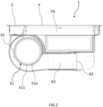
- the suction means 5 comprise a motor fan 51 having a rotation axis X-X which lies in a plane parallel to the upper surface 21.
- this rotation axis X-X is parallel to both the upper surface 21 and the walking surface of the room in which the cooking hob 1 is installed, i.e., the rotation axis X-X is orthogonal to the longitudinal axis Y-Y.
- the term "lies in a plane parallel to the upper surface 21" means that the rotation axis X-X of the motor fan 51 is substantially parallel to the surface 21, i.e., that the rotation axis X-X lies in a plane that can provide for a variation of +/- 5° with respect to the condition of parallelism.
- This variability of the parallelism condition may be due, for example, to constructional reasons of the motor fan 51, to assembly reasons or to a design choice.
- the motor fan 51 extends between a first 511 and an opposite second end 512 along the rotation axis X-X.
- the suction means 5 are configured to divide the cooking fumes into a first and a second portion of the cooking fumes directed respectively towards the first 511 and the second end 512 of the motor fan 51.
- the suction noise produced by the suction means 5 is lower than the corresponding suction noise produced by the cooking hobs of the prior art.
- this figure shows a graph with the flow rate of sucked cooking fumes shown on the abscissa axis and the intensity of the produced noise shown on the ordinate axis.
- said graph shows a first curve 100 relative to the cooking hob 1 in accordance with the present invention, a second curve 200 relative to a cooking hob of the prior art comprising a single single-suction electric motor, and a third curve 300 relative to a cooking hob of the prior art comprising a pair of single-suction electric motors.
- the noise produced by the cooking hob 1 in accordance with the present invention is equal to about 67 dBA
- the noises produced by the cooking hob of the prior art comprising a single single-suction motor fan and by the cooking hob of the prior art comprising a pair of single-suction motor fans are about 68.6 dBA and 69 dBA, respectively.
- the difference in value of the cooking hob in accordance with the present invention is therefore equal to 1.6 dBA compared to the cooking hob provided with a single single-suction motor fan and to 2 dBA compared to the cooking hob having a double single-suction motor fan.
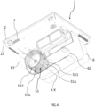
- the suction means 5 comprise a first 52 and a second suction duct 53 in fluid communication with the suction opening 4 and respectively with the first 511 and second end 512 of the motor fan 51.
- the motor fan 51 is configured to suck the first portion of the cooking fumes through the first suction duct 52 and the second portion of the cooking fumes through the second suction duct 53.
- the fluid dynamic resistance of the first suction duct 52 corresponds to the fluid dynamic resistance of the second suction duct 53. More preferably, the fluid dynamic resistance of the first suction duct 52 is substantially equal to the fluid dynamic resistance of the second suction duct 53. In the maximum preferred case, the fluid dynamic resistance of the first suction duct 52 is equal to the fluid dynamic resistance of the second suction duct 53.
- the length and the passage section of the cooking fumes of the first 52 and of the second suction duct 53 correspond to each other.
- the distribution of the cooking fumes between the first 52 and the second suction duct 53 is symmetrical.
- the first portion of the cooking fumes corresponds to the second portion of the cooking fumes.
- the cooking fume flow rate in the first suction duct 52 corresponds to the cooking fume flow rate in the second suction duct 53.
- the motor fan 51 comprises an electric motor and an impeller.
- the impeller is mechanically connected to the shaft of the electric motor. In this way, the rotation of the motor shaft of the electric motor causes the impeller to rotate and to thus be able suck the cooking fumes.
- the impeller which preferably consists of a single piece made by moulding, comprises a first half-part 51a and a second half-part 51b arranged at the first 511 and the second end 512 of the motor fan 51, respectively.
- the first half-part 51a of the impeller is configured to suck the first portion of the cooking fumes through the first suction duct 52
- the second half-part 51b of the impeller is configured to suck the second portion of the cooking fumes through the second suction duct 53.
- the cooking hob 1 comprises a pair of covering casings (or frames) 6 connected to each other so as to define a housing 61.
- the motor fan 51 is arranged in the housing 61. The motor fan 51 is therefore supported and protected by the covering casings 6.
- the covering casings 6 define the first 52 and the second suction duct 53.
- the shape and dimensions of the first 52 and second suction duct 53 are defined by the coupling between the covering casings 6.
- the cooking hob 1 comprises an operating unit 7 for the operation of the cooking hob 1, for the control thereof and for the outflow of cooking vapours through first 52 and the second suction duct 53.
- the operating unit 7 is further configured to contain at least one heating element capable of heating the at least one cooking zone 3 and a command and control electronics of the cooking hob 1.
- the operating unit 7 By means of the operating unit 7 the user can selectively adjust the heating of the cooking zone 3 and operate the suction means 5. In other words, by means of the operating unit 7 it is possible to operate the motor fan 51 and to adjust the rotation speed of said motor fan 51.
- the operating unit 7 is per se known to the person skilled in the art and will therefore not be described further.
- This operating unit 7 is arranged below the body 2 of the cooking hob 1. Preferably, this operating unit 7 is constrained to the lower surface 22 of the body 2.
- the covering casings 6 are arranged and constrained below the operating unit 7 and at least one covering casing 6 is reversibly constrained to the operating unit 7 to allow access to the housing 61.
- the covering casings 6 By removing one of the covering casings 6, it is possible to carry out maintenance activities on, for example, the motor fan 51.
- at least one covering casing 6 is reversibly constrained to the operating unit 7 to allow the motor fan 51 to be reached.
- a covering casing 6 is reversibly constrained to the operating unit 7, while the other covering casing 6 is stably constrained to the operating unit 7.
- both covering casings can be provided as reversibly constrained to the operating unit 7.
- the power supply unit (not illustrated in the accompanying figures) of the motor fan 51 is housed.
- the cooking hob 1 comprises a first 8a and a second filtering group 8b arranged in the housing 61 upstream of the respective first 52 and second suction duct 53 so as to filter the fats and the vapours that are present respectively in the first and second portion of the cooking fumes.
- the first and second portions of the cooking fumes are filtered separately, thus allowing a better filtration efficiency of the cooking fumes.
- the first 8a and the second filtering group 8b comprise respectively a grease filter comprising a metal grid and an activated carbon filter.
- the grease filter and the activated carbon filter are familiar to the person skilled in the art and will therefore not be described further.
- the suction means 5 comprise a suction chamber 54 in fluid communication with the suction opening 4.
- This suction chamber 54 is located downstream of suction opening 4.
- the suction chamber 54 is defined by the operating unit 7 and the covering casings 6.
- Said suction chamber 54 has a first 541 and a second outlet 542 in fluid communication, respectively with the first 52 and the second suction duct 53.
- the suction chamber 54 is therefore located upstream of the first 52 and the second suction duct 53.
- the suction chamber 54 is interposed between the suction opening 4 and the first 52 and the second suction duct 53.
- the separation of the cooking fumes between the first and the second portion of the cooking fumes occurs at the suction chamber 54.
- the first portion of the cooking fumes passes from the suction chamber 54 to the first suction duct 52 through the first outlet 541, while the second portion of the cooking fumes passes from the suction chamber 54 to the second suction duct 53 through the second outlet 542.
- the surface extent of the first outlet 541 corresponds to the surface extent of the second outlet 542.
- the first 8a and the second filtering group 8b are placed at the first 541 and second outlet 542 of the suction chamber 54, respectively.
- the first 8a and the second filtering group 8b are interposed between the suction chamber 54 and, respectively, the first 52 and the second suction duct 53.
- the covering casings 6 when constrained define an exhaust outlet 62 in fluid communication with the motor fan 51.
- the suction means 5 are configured to expel the cooking fumes through this exhaust outlet 62.
- the cooking fumes sucked through the suction opening 4 are then removed through the exhaust outlet 62.
- the covering casings 6, when constrained, define an exhaust duct 63.
- Said exhaust duct 63 is configured to place the motor fan 51 and the exhaust outlet 62 in fluid communication.
- this exhaust duct 63 is located downstream of the motor fan 51 and upstream of the exhaust outlet 62.
- the path of the cooking fumes from the suction opening 4 to the exhaust outlet 62 provides for the passage of the cooking fumes in the suction chamber 54 through the suction opening 4, dividing the cooking fumes into a first and a second portion of the cooking fumes at the suction chamber 54, the reaching of the first end 511 of the motor fan 51 by the first portion of the cooking fumes through the first suction duct 52, the reaching of the second end 512 of the motor fan 51 by the second portion of the cooking fumes through the second suction duct 53 and, finally, the rejoining of the first and second portion of the cooking fumes in the exhaust duct 63, before expulsion through the exhaust outlet 62.
- the exhaust outlet 62 is connectable to an outlet duct (not illustrated) of the room in which the cooking hob 1 is installed in order to let the cooking fumes outflow outside of that room.
Landscapes
- Engineering & Computer Science (AREA)
- Mechanical Engineering (AREA)
- General Engineering & Computer Science (AREA)
- Chemical & Material Sciences (AREA)
- Combustion & Propulsion (AREA)
- Ventilation (AREA)
- Baking, Grill, Roasting (AREA)
- Meat, Egg Or Seafood Products (AREA)
Applications Claiming Priority (3)
| Application Number | Priority Date | Filing Date | Title |
|---|---|---|---|
| IT102020000016360A IT202000016360A1 (it) | 2020-07-07 | 2020-07-07 | Piano cottura con cappa aspirante |
| PCT/IB2021/054806 WO2022008994A1 (fr) | 2020-07-07 | 2021-06-01 | Plaque de cuisson à hotte aspirante |
| EP21733551.2A EP4179259B1 (fr) | 2020-07-07 | 2021-06-01 | Plaque de cuisson avec dispositif d'aspiration |
Related Parent Applications (2)
| Application Number | Title | Priority Date | Filing Date |
|---|---|---|---|
| EP21733551.2A Division-Into EP4179259B1 (fr) | 2020-07-07 | 2021-06-01 | Plaque de cuisson avec dispositif d'aspiration |
| EP21733551.2A Division EP4179259B1 (fr) | 2020-07-07 | 2021-06-01 | Plaque de cuisson avec dispositif d'aspiration |
Publications (2)
| Publication Number | Publication Date |
|---|---|
| EP4528111A2 true EP4528111A2 (fr) | 2025-03-26 |
| EP4528111A3 EP4528111A3 (fr) | 2025-05-21 |
Family
ID=72644677
Family Applications (2)
| Application Number | Title | Priority Date | Filing Date |
|---|---|---|---|
| EP21733551.2A Active EP4179259B1 (fr) | 2020-07-07 | 2021-06-01 | Plaque de cuisson avec dispositif d'aspiration |
| EP25157307.7A Pending EP4528111A3 (fr) | 2020-07-07 | 2021-06-01 | Plaque de cuisson avec hotte aspirante |
Family Applications Before (1)
| Application Number | Title | Priority Date | Filing Date |
|---|---|---|---|
| EP21733551.2A Active EP4179259B1 (fr) | 2020-07-07 | 2021-06-01 | Plaque de cuisson avec dispositif d'aspiration |
Country Status (11)
| Country | Link |
|---|---|
| EP (2) | EP4179259B1 (fr) |
| JP (1) | JP7757383B2 (fr) |
| CN (1) | CN116113767A (fr) |
| CA (1) | CA3188613A1 (fr) |
| DK (1) | DK4179259T3 (fr) |
| ES (1) | ES3033090T3 (fr) |
| FI (1) | FI4179259T3 (fr) |
| IT (1) | IT202000016360A1 (fr) |
| MX (1) | MX2023000356A (fr) |
| PL (1) | PL4179259T3 (fr) |
| WO (1) | WO2022008994A1 (fr) |
Families Citing this family (3)
| Publication number | Priority date | Publication date | Assignee | Title |
|---|---|---|---|---|
| EP4246046A1 (fr) * | 2022-03-15 | 2023-09-20 | Electrolux Appliances Aktiebolag | Appareil de combinaison et procédé d'assemblage d'un appareil de combinaison |
| CN117091179A (zh) * | 2022-05-13 | 2023-11-21 | 佛山市顺德区美的电热电器制造有限公司 | 集成灶 |
| KR20250092975A (ko) * | 2023-12-15 | 2025-06-24 | 삼성전자주식회사 | 조리 기기 |
Citations (6)
| Publication number | Priority date | Publication date | Assignee | Title |
|---|---|---|---|---|
| US20130101449A1 (en) * | 2011-10-20 | 2013-04-25 | Roger Dickinson | Double Inlet Centrifugal Blower with Peripheral Motor |
| EP2778425B1 (fr) * | 2013-03-11 | 2016-10-19 | BSH Hausgeräte GmbH | Ventilateur radial à double admission pour hotte aspirante |
| EP3415777A1 (fr) * | 2017-06-13 | 2018-12-19 | ebm-papst Mulfingen GmbH & Co. KG | Partie boîtier de ventilateur doté de logement de palier ainsi que ventilateur |
| US10273963B2 (en) * | 2014-12-22 | 2019-04-30 | Whirlpool Emea S.P.A. | Extraction hood |
| DE202019106084U1 (de) | 2018-11-07 | 2019-11-15 | Elica S.P.A | Kochfläche mit Downdraft-Dunstabzugshaube |
| DE202020100040U1 (de) * | 2019-01-16 | 2020-01-27 | Elica S.P.A | Ansaugvorrichtung für eine Dunstabzugshaube für Privathaushalte |
Family Cites Families (12)
| Publication number | Priority date | Publication date | Assignee | Title |
|---|---|---|---|---|
| CN2589841Y (zh) * | 2002-07-16 | 2003-12-03 | 刘明选 | 具有双向吸烟罩的排油烟机 |
| DE202011005698U1 (de) * | 2011-04-28 | 2011-09-26 | Wilhelm Bruckbauer | Kochfeld mit zentraler Absaugung von Kochdünsten nach unten |
| JP5845395B2 (ja) * | 2011-06-09 | 2016-01-20 | パナソニックIpマネジメント株式会社 | 消音ボックス付送風機 |
| KR20140105972A (ko) * | 2013-02-25 | 2014-09-03 | 코웨이 주식회사 | 주방용 레인지 후드 |
| US9746188B2 (en) * | 2013-03-27 | 2017-08-29 | Electrolux Home Products, Inc. | Recirculating downdraft system for a cooking appliance |
| ITUA20162311A1 (it) * | 2016-04-05 | 2017-10-05 | Elica Spa | Piano cottura con cappa integrata. |
| CN106287881A (zh) * | 2016-08-22 | 2017-01-04 | 杭州奥普博朗尼厨卫科技有限公司 | 集成灶的双侧进风静音排烟装置 |
| CN110017521B (zh) * | 2017-05-22 | 2020-11-03 | 广东美的白色家电技术创新中心有限公司 | 油烟机 |
| WO2019096701A1 (fr) * | 2017-11-17 | 2019-05-23 | BSH Hausgeräte GmbH | Dispositif d'aspiration des fumées pour une table de cuisson et meuble de cuisine doté d'un dispositif d'aspiration des fumées |
| DE102017223828A1 (de) * | 2017-12-27 | 2019-06-27 | Wilhelm Bruckbauer | Dunstabzugsvorrichtung zum Abzug von Kochdünsten nach unten |
| US11885505B2 (en) * | 2018-04-10 | 2024-01-30 | BSH Hausgeräte GmbH | Filter device and fume extraction device comprising filter device |
| CN210717736U (zh) * | 2019-07-29 | 2020-06-09 | 九阳股份有限公司 | 一种辅助排气的集成灶 |
-
2020
- 2020-07-07 IT IT102020000016360A patent/IT202000016360A1/it unknown
-
2021
- 2021-06-01 CA CA3188613A patent/CA3188613A1/fr active Pending
- 2021-06-01 PL PL21733551.2T patent/PL4179259T3/pl unknown
- 2021-06-01 WO PCT/IB2021/054806 patent/WO2022008994A1/fr not_active Ceased
- 2021-06-01 MX MX2023000356A patent/MX2023000356A/es unknown
- 2021-06-01 CN CN202180051762.2A patent/CN116113767A/zh active Pending
- 2021-06-01 ES ES21733551T patent/ES3033090T3/es active Active
- 2021-06-01 FI FIEP21733551.2T patent/FI4179259T3/fi active
- 2021-06-01 JP JP2023501148A patent/JP7757383B2/ja active Active
- 2021-06-01 DK DK21733551.2T patent/DK4179259T3/da active
- 2021-06-01 EP EP21733551.2A patent/EP4179259B1/fr active Active
- 2021-06-01 EP EP25157307.7A patent/EP4528111A3/fr active Pending
Patent Citations (6)
| Publication number | Priority date | Publication date | Assignee | Title |
|---|---|---|---|---|
| US20130101449A1 (en) * | 2011-10-20 | 2013-04-25 | Roger Dickinson | Double Inlet Centrifugal Blower with Peripheral Motor |
| EP2778425B1 (fr) * | 2013-03-11 | 2016-10-19 | BSH Hausgeräte GmbH | Ventilateur radial à double admission pour hotte aspirante |
| US10273963B2 (en) * | 2014-12-22 | 2019-04-30 | Whirlpool Emea S.P.A. | Extraction hood |
| EP3415777A1 (fr) * | 2017-06-13 | 2018-12-19 | ebm-papst Mulfingen GmbH & Co. KG | Partie boîtier de ventilateur doté de logement de palier ainsi que ventilateur |
| DE202019106084U1 (de) | 2018-11-07 | 2019-11-15 | Elica S.P.A | Kochfläche mit Downdraft-Dunstabzugshaube |
| DE202020100040U1 (de) * | 2019-01-16 | 2020-01-27 | Elica S.P.A | Ansaugvorrichtung für eine Dunstabzugshaube für Privathaushalte |
Also Published As
| Publication number | Publication date |
|---|---|
| FI4179259T3 (fi) | 2025-06-27 |
| IT202000016360A1 (it) | 2022-01-07 |
| JP7757383B2 (ja) | 2025-10-21 |
| CN116113767A (zh) | 2023-05-12 |
| DK4179259T3 (da) | 2025-06-30 |
| EP4179259B1 (fr) | 2025-03-26 |
| EP4179259A1 (fr) | 2023-05-17 |
| MX2023000356A (es) | 2023-03-06 |
| JP2023532779A (ja) | 2023-07-31 |
| PL4179259T3 (pl) | 2025-09-22 |
| EP4528111A3 (fr) | 2025-05-21 |
| US20230258340A1 (en) | 2023-08-17 |
| ES3033090T3 (en) | 2025-07-30 |
| CA3188613A1 (fr) | 2022-01-13 |
| WO2022008994A1 (fr) | 2022-01-13 |
Similar Documents
| Publication | Publication Date | Title |
|---|---|---|
| JP6852088B2 (ja) | 一体化フードを持つ調理用レンジ | |
| EP4179259B1 (fr) | Plaque de cuisson avec dispositif d'aspiration | |
| EP3380791B1 (fr) | Hotte à usage domestique | |
| EP3037671B1 (fr) | Dispositif d'aspiration destiné à une hotte, équipé d'un connecteur électrique | |
| EP3491296B1 (fr) | Table de cuisson | |
| CN111051779A (zh) | 灶具 | |
| US12618568B2 (en) | Cooking hob with extractor hood | |
| CN218510972U (zh) | 一种吸油烟机 | |
| EA045882B1 (ru) | Варочная панель для приготовления пищи с вытяжкой | |
| CN111810994A (zh) | 家用电器与烹饪系统 | |
| WO2018015823A1 (fr) | Plaque de cuisson | |
| CN214700817U (zh) | 集成灶 | |
| US20250207784A1 (en) | Cooking appliance with a filter | |
| CN113685869B (zh) | 一种集成灶及其控制方法 | |
| WO2025172826A1 (fr) | Table de cuisson | |
| WO2026013610A1 (fr) | Appareil électroménager pour la cuisson de plats pourvu d'une plaque de cuisson et d'une hotte à aspiration descendante | |
| KR200197578Y1 (ko) | 후드겸용 전자렌지의 밑판구조 | |
| CN116464651A (zh) | 空气循环组件和储物柜 |
Legal Events
| Date | Code | Title | Description |
|---|---|---|---|
| PUAI | Public reference made under article 153(3) epc to a published international application that has entered the european phase |
Free format text: ORIGINAL CODE: 0009012 |
|
| STAA | Information on the status of an ep patent application or granted ep patent |
Free format text: STATUS: THE APPLICATION HAS BEEN PUBLISHED |
|
| AC | Divisional application: reference to earlier application |
Ref document number: 4179259 Country of ref document: EP Kind code of ref document: P |
|
| AK | Designated contracting states |
Kind code of ref document: A2 Designated state(s): AL AT BE BG CH CY CZ DE DK EE ES FI FR GB GR HR HU IE IS IT LI LT LU LV MC MK MT NL NO PL PT RO RS SE SI SK SM TR |
|
| REG | Reference to a national code |
Ref country code: DE Ref legal event code: R079 Free format text: PREVIOUS MAIN CLASS: F04D0029700000 Ipc: F24C0015200000 |
|
| PUAL | Search report despatched |
Free format text: ORIGINAL CODE: 0009013 |
|
| AK | Designated contracting states |
Kind code of ref document: A3 Designated state(s): AL AT BE BG CH CY CZ DE DK EE ES FI FR GB GR HR HU IE IS IT LI LT LU LV MC MK MT NL NO PL PT RO RS SE SI SK SM TR |
|
| RIC1 | Information provided on ipc code assigned before grant |
Ipc: F04D 29/60 20060101ALI20250411BHEP Ipc: F04D 29/70 20060101ALI20250411BHEP Ipc: F04D 29/66 20060101ALI20250411BHEP Ipc: F04D 29/42 20060101ALI20250411BHEP Ipc: F04D 25/08 20060101ALI20250411BHEP Ipc: F04D 17/16 20060101ALI20250411BHEP Ipc: F24C 15/20 20060101AFI20250411BHEP |
|
| STAA | Information on the status of an ep patent application or granted ep patent |
Free format text: STATUS: REQUEST FOR EXAMINATION WAS MADE |
|
| 17P | Request for examination filed |
Effective date: 20251120 |
|
| STAA | Information on the status of an ep patent application or granted ep patent |
Free format text: STATUS: EXAMINATION IS IN PROGRESS |
|
| 17Q | First examination report despatched |
Effective date: 20260326 |