EP4528164A2 - Verbrennungsabschnitt mit einer primärbrennkammer und einem satz von sekundärbrennkammern - Google Patents
Verbrennungsabschnitt mit einer primärbrennkammer und einem satz von sekundärbrennkammern Download PDFInfo
- Publication number
- EP4528164A2 EP4528164A2 EP24192505.6A EP24192505A EP4528164A2 EP 4528164 A2 EP4528164 A2 EP 4528164A2 EP 24192505 A EP24192505 A EP 24192505A EP 4528164 A2 EP4528164 A2 EP 4528164A2
- Authority
- EP
- European Patent Office
- Prior art keywords
- combustor
- primary
- mini
- combustion section
- combustion
- Prior art date
- Legal status (The legal status is an assumption and is not a legal conclusion. Google has not performed a legal analysis and makes no representation as to the accuracy of the status listed.)
- Pending
Links
Images



Classifications
-
- F—MECHANICAL ENGINEERING; LIGHTING; HEATING; WEAPONS; BLASTING
- F23—COMBUSTION APPARATUS; COMBUSTION PROCESSES
- F23R—GENERATING COMBUSTION PRODUCTS OF HIGH PRESSURE OR HIGH VELOCITY, e.g. GAS-TURBINE COMBUSTION CHAMBERS
- F23R3/00—Continuous combustion chambers using liquid or gaseous fuel
- F23R3/28—Continuous combustion chambers using liquid or gaseous fuel characterised by the fuel supply
- F23R3/34—Feeding into different combustion zones
- F23R3/346—Feeding into different combustion zones for staged combustion
-
- F—MECHANICAL ENGINEERING; LIGHTING; HEATING; WEAPONS; BLASTING
- F23—COMBUSTION APPARATUS; COMBUSTION PROCESSES
- F23R—GENERATING COMBUSTION PRODUCTS OF HIGH PRESSURE OR HIGH VELOCITY, e.g. GAS-TURBINE COMBUSTION CHAMBERS
- F23R3/00—Continuous combustion chambers using liquid or gaseous fuel
- F23R3/02—Continuous combustion chambers using liquid or gaseous fuel characterised by the air-flow or gas-flow configuration
- F23R3/04—Air inlet arrangements
- F23R3/06—Arrangement of apertures along the flame tube
-
- F—MECHANICAL ENGINEERING; LIGHTING; HEATING; WEAPONS; BLASTING
- F23—COMBUSTION APPARATUS; COMBUSTION PROCESSES
- F23R—GENERATING COMBUSTION PRODUCTS OF HIGH PRESSURE OR HIGH VELOCITY, e.g. GAS-TURBINE COMBUSTION CHAMBERS
- F23R3/00—Continuous combustion chambers using liquid or gaseous fuel
- F23R3/42—Continuous combustion chambers using liquid or gaseous fuel characterised by the arrangement or form of the flame tubes or combustion chambers
-
- F—MECHANICAL ENGINEERING; LIGHTING; HEATING; WEAPONS; BLASTING
- F23—COMBUSTION APPARATUS; COMBUSTION PROCESSES
- F23R—GENERATING COMBUSTION PRODUCTS OF HIGH PRESSURE OR HIGH VELOCITY, e.g. GAS-TURBINE COMBUSTION CHAMBERS
- F23R3/00—Continuous combustion chambers using liquid or gaseous fuel
- F23R3/42—Continuous combustion chambers using liquid or gaseous fuel characterised by the arrangement or form of the flame tubes or combustion chambers
- F23R3/50—Combustion chambers comprising an annular flame tube within an annular casing
Definitions
- the present subject matter relates generally to a combustion section of a turbine engine, and more specifically to a combustion section with a primary combustor and a secondary combustor.
- Turbine engines are driven by a flow of combustion gases passing through the engine to rotate a multitude of turbine blades, which, in turn, rotate a compressor to provide compressed air to the combustor for combustion.
- a combustor can be provided within the turbine engine and is fluidly coupled with a turbine into which the combusted gases flow.
- hydrocarbon fuels in the combustor of a turbine engine
- air and fuel are fed to a combustion chamber, the air and fuel are mixed, and then the fuel is burned in the presence of the air to produce hot gas.
- the hot gas is then fed to a turbine where it cools and expands to produce power.
- By-products of the fuel combustion typically include environmentally unwanted by-products, such as nitrogen oxide and nitrogen dioxide (collectively called NO x ), carbon monoxide (CO), unburned hydrocarbons (UHC) (e.g., methane and volatile organic compounds that contribute to the formation of atmospheric ozone), and other oxides, including oxides of sulfur (e.g., SO 2 and SO 3 ).
- NO x nitrogen oxide and nitrogen dioxide
- CO carbon monoxide
- UHC unburned hydrocarbons
- SO 2 and SO 3 oxides of sulfur
- Hydrogen or hydrogen mixed with another element or compound can be used for combustion, however hydrogen or a hydrogen mixed fuel can result in a higher flame temperature than traditional fuels. That is, hydrogen or a hydrogen mixed fuel typically has a wider flammable range and a faster burning velocity than traditional fuels such as petroleum-based fuels, or petroleum and synthetic fuel blends.
- NO x is formed within the combustor as a result of high combustor flame temperatures during operation. It is desirable to decrease NO x emissions while still maintaining desirable efficiencies by regulating the temperature profile and or flame pattern within the combustor.
- aspects of the disclosure described herein are directed to a combustion section, and in particular a combustion section with a primary combustor and a secondary combustor.
- a combustion section as described herein can be implemented in engines, including but not limited to turbojet, turboprop, turboshaft, and turbofan engines.
- Aspects of the disclosure discussed herein may have general applicability within non-aircraft engines having a combustor, such as other mobile applications and non-mobile industrial, commercial, and residential applications.
- first, second, and third may be used interchangeably to distinguish one component from another and are not intended to signify location or importance of the individual components.
- forward and aft refer to relative positions within a gas turbine engine or vehicle, and refer to the normal operational attitude of the gas turbine engine or vehicle.
- forward refers to a position closer to an engine inlet and aft refers to a position closer to an engine nozzle or exhaust.
- upstream refers to a direction that is opposite the fluid flow direction
- downstream refers to a direction that is in the same direction as the fluid flow.
- forward means in front of something and "aft” or “rearward” means behind something.
- fore/forward can mean upstream and aft/rearward can mean downstream.
- fluid may be a gas or a liquid.
- fluidly couples and “fluidly coupled” mean that a fluid is capable of making the connection between the areas specified.
- radial refers to a direction away from a common center.
- radial refers to a direction along a ray extending between a center longitudinal axis of the engine and an outer engine circumference.
- All directional references may be used for identification purposes to aid the reader's understanding of the present disclosure, and do not create limitations, particularly as to the position, orientation, or use of aspects of the disclosure described herein.
- Connection references e.g., attached, coupled, connected, and joined
- connection references may be used and are to be construed broadly and can include intermediate structural elements between a collection of elements and relative movement between elements unless otherwise indicated. As such, connection references do not necessarily infer that two elements are directly connected and in fixed relation to one another.
- the exemplary drawings are for purposes of illustration only the dimensions, positions, order and relative sizes reflected in the drawings attached hereto can vary.
- Approximating language is applied to modify any quantitative representation that could permissibly vary without resulting in a change in the basic function to which it is related. Accordingly, a value modified by a term or terms, such as “about”, “approximately”, “generally”, and “substantially”, are not to be limited to the precise value specified.
- the approximating language may correspond to the precision of an instrument for measuring the value, or the precision of the methods or machines for constructing or manufacturing the components and/or systems. In at least some instances, the approximating language may correspond to the precision of an instrument for measuring the value, or the precision of the methods or machines for constructing or manufacturing the components and/or systems.
- the approximating language may refer to being within a 1, 2, 4, 5, 10, 15, or 20 percent margin in either individual values, range(s) of values and/or endpoints defining range(s) of values.
- range limitations are combined and interchanged, such ranges are identified and include all the sub-ranges contained therein unless context or language indicates otherwise.
- all ranges disclosed herein are inclusive of the endpoints, and the endpoints are independently combinable with each other.
- FIG. 1 is a schematic view of a turbine engine 10.
- the turbine engine 10 can be used within an aircraft.
- the turbine engine 10 can include, at least, a compressor section 12, a combustion section 14, and a turbine section 16.
- a drive shaft 18 rotationally couples the compressor section 12 and the turbine section 16, such that rotation of one affects the rotation of the other, and defines a rotational axis or centerline 20 for the turbine engine 10.
- the compressor section 12 can include a low-pressure (LP) compressor 22, and a high-pressure (HP) compressor 24 serially fluidly coupled to one another.
- the turbine section 16 can include an LP turbine 26, and an HP turbine 28 serially fluidly coupled to one another.
- the drive shaft 18 can operatively couple the LP compressor 22, the HP compressor 24, the LP turbine 26 and the HP turbine 28 together.
- the drive shaft 18 can include an LP drive shaft (not illustrated) and an HP drive shaft (not illustrated).
- the LP drive shaft can couple the LP compressor 22 to the LP turbine 26, and the HP drive shaft can couple the HP compressor 24 to the HP turbine 28.
- An LP spool can be defined as the combination of the LP compressor 22, the LP turbine 26, and the LP drive shaft such that the rotation of the LP turbine 26 can apply a driving force to the LP drive shaft, which in turn can rotate the LP compressor 22.
- An HP spool can be defined as the combination of the HP compressor 24, the HP turbine 28, and the HP drive shaft such that the rotation of the HP turbine 28 can apply a driving force to the HP drive shaft which in turn can rotate the HP compressor 24.
- the compressor section 12 can include a plurality of axially spaced stages. Each stage includes a set of circumferentially-spaced rotating blades and a set of circumferentially-spaced stationary vanes.
- the compressor blades for a stage of the compressor section 12 can be mounted to a disk, which is mounted to the drive shaft 18. Each set of blades for a given stage can have its own disk.
- the vanes of the compressor section 12 can be mounted to a casing which can extend circumferentially about the turbine engine 10. It will be appreciated that the representation of the compressor section 12 is merely schematic and that there can be any number of stages. Further, it is contemplated, that there can be any other number of components within the compressor section 12.
- the turbine section 16 can include a plurality of axially spaced stages, with each stage having a set of circumferentially-spaced, rotating blades and a set of circumferentially-spaced, stationary vanes.
- the turbine blades for a stage of the turbine section 16 can be mounted to a disk which is mounted to the drive shaft 18.
- Each set of blades for a given stage can have its own disk.
- the vanes of the turbine section 16 can be mounted to the casing in a circumferential manner. It is noted that there can be any number of blades, vanes and turbine stages as the illustrated turbine section is merely a schematic representation. Further, it is contemplated, that there can be any other number of components within the turbine section 16.
- the combustion section 14 can be provided serially between the compressor section 12 and the turbine section 16.
- the combustion section 14 can be fluidly coupled to at least a portion of the compressor section 12 and the turbine section 16 such that the combustion section 14 at least partially fluidly couples the compressor section 12 to the turbine section 16.
- the combustion section 14 can be fluidly coupled to the HP compressor 24 at an upstream end of the combustion section 14 and to the HP turbine 28 at a downstream end of the combustion section 14.
- ambient or atmospheric air is drawn into the compressor section 12 via a fan (not illustrated) upstream of the compressor section 12, where the air is compressed defining a pressurized air.
- the pressurized air can then flow into the combustion section 14 where the pressurized air is mixed with fuel and ignited, thereby generating combustion gases.
- Some work is extracted from these combustion gases by the HP turbine 28, which drives the HP compressor 24.
- the combustion gases are discharged into the LP turbine 26, which extracts additional work to drive the LP compressor 22, and the exhaust gas is ultimately discharged from the turbine engine 10 via an exhaust section (not illustrated) downstream of the turbine section 16.
- the driving of the LP turbine 26 drives the LP spool to rotate the fan (not illustrated) and the LP compressor 22.
- the pressurized airflow and the combustion gases can together define a working airflow that flows through the fan, compressor section 12, combustion section 14, and turbine section 16 of the turbine engine 10.
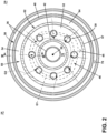
- FIG. 2 depicts a cross-sectional view of the combustion section 14 along line II-II of FIG. 1 defining a transverse plane (denoted "TP").
- the combustion section 14 can include an annular arrangement of primary fuel injectors 30 disposed around the centerline 20 of the turbine engine 10. Each of the primary fuel injectors 30 are fluidly coupled to a primary combustor 32. It should be appreciated that the annular arrangement of fuel injectors can be one or multiple fuel injectors and one or more of the primary fuel injectors 30 can have different characteristics.
- the primary combustor 32 can have a can, can-annular, or annular arrangement depending on the type of engine in which the primary combustor 32 is located.
- annular arrangement is illustrated and disposed within a casing 36.
- the primary combustor 32 is defined by a primary combustor liner 38 including an outer liner 40 and an inner liner 42 concentric with respect to each other and annular about the centerline 20.
- a dome wall 44 together with the primary combustor liner 38 define a primary combustion chamber 46 annular about the centerline 20.
- a compressed air passageway 70 can surround the primary combustor 32 and be at least partially defined by the casing 36.
- the combustion section 14 further includes a set of secondary combustors 50 comprising an annular mini combustor 34.
- mini means that the component referenced with the term mini is smaller than the corresponding like component without the term mini (i.e., the annular mini combustor 34 is smaller than the primary combustor 32).
- the annular mini combustor 34 is defined by a secondary combustor liner 52 concentric with respect to the outer liner 40 and the inner liner 42 and annular about the centerline 20.
- the secondary combustor liner 52 together with the outer liner 40 defines at least a portion of a secondary combustion chamber 54 circumferentially arranged about the centerline 20.
- the annular mini combustor 34 is open to the primary combustor 32. More specifically, the secondary combustor liner 52 terminates at an end 57 axially downstream from the primary fuel injectors 30.
- the primary combustor 32 produces primary exhaust gasses (denoted “G1") in the primary combustion chamber 46.
- the set of secondary combustors 50 produce secondary exhaust gasses (denoted “G2") in the secondary combustion chamber 54 that flow into the primary combustion chamber 46.
- the secondary exhaust gasses G2 circulate in the primary combustion chamber 46 starving O 2 levels and reducing temperatures in the primary combustion chamber 46. This results in a reduction of NO x emissions.
- FIG. 3 depicts a cross-sectional view taken along line III-III of FIG. 2 illustrating the combustion section 14 as viewed in a radial plane (denoted "RP"). It can more clearly be seen that annular mini combustor 34 is open to the primary combustor 32.
- the primary combustor 32 extends between the dome wall 44 and a primary combustor outlet 48 fluidly coupled to the turbine section 16 ( FIG. 1 ).
- a dome assembly 60 includes the dome wall 44 and houses the primary fuel injector 30.
- the primary fuel injector 30 can be fluidly coupled to a fuel inlet 62 via a fuel passageway 64 that can be adapted to receive a primary flow of fuel (denoted "F1").
- the primary fuel injector 30 can terminate in a fuel outlet also referred to herein as a dome inlet 66.
- the primary fuel injector 30 can include a swirler 68 circumferentially arranged about the dome inlet 66.
- a primary igniter 61 is fluidly coupled to the primary combustion chamber 46.
- a backwall 51 extends radially from the end 57 to connect the secondary combustor liner 52 to the outer liner 40.
- the secondary combustor liner 52 terminates in the end 57 located downstream from the dome inlet 66.
- a primary set of dilution openings 77 can be located downstream from the annular mini combustor 34 in both the outer liner 40 and the inner liner 42. It is further contemplated that the set of dilution openings 77 is located at any location, including upstream from the annular mini combustor 34.
- the annular mini combustor 34 includes at least one mini dome assembly 80 including a mini dome wall 82 and housing a mini fuel injector 84.
- the at least one mini dome assembly 80 can be multiple dome assemblies arranged circumferentially about the annular mini combustor 34.
- the mini fuel injector 84 can be fluidly coupled to a secondary fuel passageway 86 that can be adapted to receive a secondary flow of fuel (denoted "F2").
- the mini fuel injector 84 terminates in a secondary fuel outlet also referred to herein as a mini dome inlet 88 open to the secondary combustion chamber 54. While illustrated as radially aligned, it is contemplated that the mini dome inlet 88 is circumferentially staggered with respect to the dome inlet 66.
- the mini fuel injector 84 can include a swirler (not shown). It is further contemplated that the set of secondary combustors do not include a swirler, but can have non swirling air passages.
- a secondary igniter 63 is fluidly coupled to the secondary combustion chamber 54.
- the dome inlet 66 defines a first centerline (denoted “CL1”).
- the mini dome inlet 88 defines a second centerline (denoted “CL2") extending toward the primary combustion chamber 46.
- the first centerline CL1 and the second centerline CL2 intersect to define a first primary combustor angle (denoted " ⁇ 1 ") in the radial plane RP.
- the first primary combustor angle ⁇ 1 can be 90° as illustrated.
- the mini dome inlet 88 can be angled as well, such that the first primary combustor angle ⁇ 1 ranges from 90° to 165°.
- a primary combustor length (denoted “L1”) is measured parallel to the first centerline CL1 between the dome wall 44 and the primary combustor outlet 48.
- a main combustion zone 72 is defined as the volume between the dome wall 44 and the second centerline CL2.
- a main combustion length (denoted “L M ”) is measured parallel to the first centerline CL1 from the dome wall 44 to the second centerline CL2.
- the main combustion length L M is from 5% to 90% of the primary combustor length L1.
- the main combustion length L M can be 5% to 70%, 5% to 50%, or 5% to 40% of the primary combustor length L1.
- the primary combustion chamber 46 has a radial dimension extending from the inner liner 42 to the secondary combustor liner 52 and referred to herein as a primary combustor height (denoted “H").
- the primary combustor height H can be measured proximate the dome wall 44.
- a separating line (denoted “S L ”) extends axially from the end 57 parallel to the first centerline CL1 at the primary combustor height H.
- the separating line S L separates the primary combustion chamber 46 from the secondary combustion chamber 54.
- a mini combustor height (denoted “H M ”) is defined as a radial dimension extending from the secondary combustor liner 52 to the outer liner 40.
- the backwall 51 extends radially toward the mini dome inlet 88 an amount equal to the mini combustor height H M .
- the mini combustor height H M varies from 0.0H to 0.6H. In other words, the mini combustor height H M measurement is an amount up to and including 60% of the primary combustor height H.
- the mini combustor height H M is maintained between the separating line SL and the outer liner 40 to define a mini combustion zone 74.
- the mini combustion zone 74 is spaced radially outward and axially downstream from the main combustion zone 72.
- compressed air (denoted “C") can be provided to the combustion section 14 from the compressor section 12 ( FIG. 1 ) via the compressed air passageway 70.
- the compressed air C can be split between the primary combustor 32 and the set of secondary combustors 50 such that the primary combustor 32 receives 60% to 90% of the compressed air C from the compressor section 12 while the set of secondary combustors 50 receives between 10% and 40%.
- Compressed air C can be fed into the primary fuel injector 30 and mixed with the primary flow of fuel F1 to define a primary fuel/air mixture (denoted "FA1").
- the primary fuel injector 30 along with the primary igniter 61 define a primary burn system having a primary flame.
- the primary fuel injector 30 can dispense a primary fuel/air mixture FA1 that is premixed or partially premixed. Further the flow of fuel F1 can be a diffusion fuel free of an air mixture prior to entering the primary combustion chamber 46.
- the primary burn system can be a rich burn system or a lean burn system.
- a rich burn combustion system includes a fuel/air ratio above the stoichiometric fuel/air ratio whereas a lean burn combustion system includes a fuel/air ratio below the stoichiometric fuel/air ratio.
- a rich burn system for the primary combustor 32 will create a higher temperature within the primary combustion chamber 46 providing flame stability to the overall combustion system.
- NO x is reduced from the secondary combustion chamber 54.
- the primary combustor 32 can be a lean burn system for lower NO x from the primary combustion chamber 46 with the set of secondary combustors 50 having a rich burn system for providing flame stability to the primary combustor 32 and the entire combustion system.
- Compressed air C can be fed into the mini fuel injector 84 and mixed with the secondary flow of fuel F2 to define a secondary fuel/air mixture (denoted "FA2").
- the mini fuel injector 84 along with the secondary igniter 63 can define a mini burn system including a secondary flame that can be premixed, partially premixed, or diffusion.
- the mini burn system can be a rich burn system or a lean burn system.
- Fuel provided to the primary fuel injectors 30 and the mini fuel injectors 84 can include jet fuel natural gas or a more reacting fuel like H 2 and blends of H 2 .
- the turbine engine 10 can be started on conventional fuel using the set of secondary combustors 50 where the secondary exhaust gasses G2 ( FIG. 2 ) are propagated towards the primary combustion chamber 46 which can be fueled using conventional fuel or H 2 fuel.
- both the primary combustor 32 and the set of secondary combustors 50 can be a rich burn system or a lean burn system. With both having lean burn systems, the NOx emissions are greatly reduced. However, at least one or more of the primary fuel injectors 30 or mini fuel injectors 84 will need to be fuel rich to provide flame stability. Likewise, both the primary combustor 32 and the set of secondary combustors 50 can have rich burn systems where lowering NOx in this system is achieved by staging fuel and starvation of O 2 in the primary combustor 32 from product released from the set of secondary combustors 50 that produces lower NOx.
- the primary exhaust gasses G1 ( FIG. 2 ) and the secondary exhaust gasses G2 mix which reduces O 2 levels in the primary combustion chamber 46 that reduces NOx emissions.
- Fuel staging between the primary combustion chamber 46 and the secondary combustion chamber 54 reduces the fuel/air ratio in these stages of the combustion section 14 which contributes to a further reduction in temperature and NOx emissions. In comparison a single staged combustor will have relatively higher fuel/air ratios and higher temperatures which leads to higher NOx emissions.
- the main combustion zone 72 can have a combustion residence time that ranges from 2ms to 8ms, inclusive of endpoints.
- the mini combustion zone 74 can have a combustion residence time that ranges from 0.1ms to 2ms, inclusive of endpoints.
- the total combustion residence time for the combustion section 14 can range from 2ms to 10ms, inclusive of endpoints.
- the primary combustor 32 can have an equivalence ratio from 0.5 to 2, inclusive of endpoints.
- the annular mini combustor 34 can have an equivalence ratio from 0.4 to 2, inclusive of endpoints.
- FIG. 4 depicts a cross-sectional view of another embodiment of a combustion section 114 as viewed in a radial plane (denoted "RP").
- the combustion section 114 is similar to the combustion section 14 of FIG. 3 ; therefore, like parts will be identified with like numerals increased by 100, with it being understood that the description of the like parts of the combustion section 14 applies to the combustion section 114, except where noted.
- a primary combustor 132 is provided within a casing 136 and extends between a dome wall 144 and a primary combustor outlet 148 fluidly connected to the turbine section 16 ( FIG. 1 ).
- An outer liner 140 is spaced radially from an inner liner 142 to define a primary combustion chamber 146 of the primary combustor 132.
- a dome assembly 160 includes the dome wall 144 and houses a primary fuel injector 130.
- the primary fuel injector 130 can be fluidly coupled to a fuel inlet 162 via a fuel passageway 164 that can be adapted to receive a primary flow of fuel (denoted "F1").
- the primary fuel injector 130 can terminate in a fuel outlet also referred to herein as a dome inlet 166.
- the primary fuel injector 130 can include a swirler 168 circumferentially arranged about the dome inlet 166.
- a primary igniter 161 is fluidly coupled to the primary combustion chamber 146.
- At least one opening 157 extends through the outer liner 140 and is located downstream from the dome inlet 66.
- a set of dilution openings 177 can be located downstream from the at least one opening 157 in the inner liner 142. It is further contemplated that a primary combustor liner 138 can include any number of dilution openings 177 at any location including upstream from the at least one opening 157and also within the outer liner 140.
- the combustion section 114 further includes a set of secondary combustors 150 comprising at least one annular mini combustor 134.
- the at least one mini combustor 134 includes a secondary combustor liner 152 defining a secondary combustion chamber 154.
- the at least one mini combustor 134 includes a mini dome assembly 180 including a mini dome wall 182 and housing a mini fuel injector 184.
- the mini fuel injector 184 can be fluidly coupled to a secondary fuel passageway 186 that can be adapted to receive a secondary flow of fuel (denoted "F2").
- the mini fuel injector 184 terminates in a secondary fuel outlet also referred to herein as a mini dome inlet 188 open to the secondary combustion chamber 154.
- the secondary combustion chamber 154 is fluidly coupled to the primary combustion chamber 146 at the at least one opening 157to define a secondary combustor outlet 158.
- the mini fuel injector 184 can include a low swirl number swirler 189, i.e., with a number less than 1 and having a low tangential velocity, circumferentially arranged about the mini dome inlet 188. It is further contemplated that the at least one mini combustor 134 does not include a swirler, but can have non swirling air passages.
- a secondary igniter 163 is fluidly coupled to the secondary combustion chamber 154.
- the at least one mini combustor 134 includes a gradually converging body 176.
- the gradually converging body 176 is defined as a portion of the at least one mini combustor 134 where a first cross-sectional area (denoted "CA1”) proximate the mini dome inlet 188 is greater than a second cross-sectional area (denoted "CA2”) proximate the secondary combustor outlet 158.
- a secondary set of dilution openings 178 can be provided in the secondary combustor liner 152 for connecting a compressed air passageway 170 and the secondary combustion chamber 154.
- the secondary set of dilution openings 178 are at an aft location of the at least one mini combustor 134 for trimming a combustor exit temperature profile and pattern factor associated with the at least one mini combustor 134 and primary combustor 132.
- the outer liner 140 defines a primary combustor height H of the primary combustor 132 proximate the dome wall 144 and measured radially between the inner liner 142 and the outer liner 140.
- a mini combustor height H M is defined as a radial dimension extending from the outer liner 140 to the mini dome wall 182.
- the mini combustor height H M varies from 0.0H to 0.6H.
- the mini combustor height H M measurement is an amount up to and including 60% of the primary combustor height H.
- the secondary combustor liner 152 defines a mini combustion zone 174.
- the mini combustion zone 174 is radially and axially spaced away from a main combustion zone 172.
- the dome inlet 166 defines a first centerline CL1.
- the mini dome inlet 188 defines a second centerline CL2 extending toward the secondary combustor outlet 158.
- the secondary combustor outlet 158 intersects the second centerline CL2 to define a geometric center 190 of the secondary combustor outlet 158.
- the first centerline CL1 and the second centerline CL2 intersect to define a second primary combustor angle (denoted " ⁇ 2 ") in the radial plane RP.
- the at least one mini combustor 134 can be angled toward the primary combustor outlet 148 such that the second primary combustor angle ⁇ 2 is greater than 90°.
- the at least one mini combustor 134 when angled toward the primary combustor outlet 148, has a second primary combustor angle ⁇ 2 that can vary from 90° to 165°.
- the process of directing the secondary exhaust gasses G2 from the at least one mini combustor 34 into the primary combustion chamber 46 at the second primary combustor angle ⁇ 2 improves turbulence levels. Further the gradually converging body 176 accelerates the secondary fuel/air mixture FA2 exiting the secondary combustor outlet 158 into the primary combustion chamber 146, this further improves turbulence levels. Turbulence helps to thoroughly mix the primary and secondary exhaust gasses G1, G2 which improves a uniform temperature distribution, again resulting in a reduction in NO x .
- FIG. 5 depicts a cross-sectional view of yet another embodiment of a combustion section 214 as viewed in a radial plane (denoted "RP").
- the combustion section 214 is similar to the combustion section 114 of FIG. 4 ; therefore, like parts will be identified with like numerals increased by 100, with it being understood that the description of the like parts of the combustion section 114 applies to the combustion section 214, except where noted.
- a primary combustor 232 extends between a dome wall 244 and a primary combustor outlet 248 fluidly connected to the turbine section 16 ( FIG. 1 ).
- An outer liner 240 is spaced radially from an inner liner 242, together defining a primary combustor liner 238.
- the primary combustor liner 238 defining at least a portion of a primary combustion chamber 246 of the primary combustor 232.
- a dome assembly 260 includes the dome wall 244 and houses a primary fuel injector 230.
- the primary fuel injector 230 can be fluidly coupled to a fuel inlet 262 via a fuel passageway 264 that can be adapted to receive a primary flow of fuel (denoted "F1").
- the primary fuel injector 230 can terminate in a fuel outlet also referred to herein as a dome inlet 266 and located in a dome assembly 260.
- the primary fuel injector 230 can include a swirler 268 circumferentially arranged about the dome inlet 266.
- a primary igniter 261 is fluidly coupled to the primary combustion chamber 246. At least one opening 257 extends through the outer liner 240 and is located downstream from the dome inlet 266.
- a set of dilution openings 277 can be located upstream from a mini dome inlet 288 in the outer liner 240 and also within the inner liner 242. It is further contemplated that the primary combustor liner 238 can include any number of dilution openings at any location including downstream from the mini dome inlet 288 in the outer liner 240 and also within the inner liner 242.
- the combustion section 214 further includes a set of secondary combustors 250 comprising at least one mini combustor 234.
- the at least one mini combustor 234 includes a secondary combustor liner 252 defining a secondary combustion chamber 254.
- the at least one mini combustor 234 includes a mini dome assembly 280 including a mini dome wall 282 and housing a mini fuel injector 284.
- the mini fuel injector 284 can be fluidly coupled to a secondary fuel passageway 286 that can be adapted to receive a secondary flow of fuel (denoted "F2").
- the mini fuel injector 284 terminates in a secondary fuel outlet also referred to herein as a mini dome inlet 288 open to the secondary combustion chamber 254.
- the mini fuel injector 284 can include a low swirl number swirler 289, i.e., with a number less than 1 and having a low tangential velocity, circumferentially arranged about the mini dome inlet 288. It is further contemplated that the at least one mini combustor 234 does not include a swirler, but can have non-swirling air passages.
- a secondary igniter 263 is fluidly coupled to the secondary combustion chamber 254. The secondary igniter 263 is fluidly coupled to the secondary combustion chamber 254.
- the dome inlet 266 defines a first centerline CL1.
- the mini dome inlet 288 can define a second centerline CL2 extending toward a secondary combustor outlet 258.
- the secondary combustor outlet 258 intersects the second centerline CL2 to define a geometric center 290 of the secondary combustor outlet 258.
- the at least one mini combustor 234 can have a constant area cross-section along the second centerline CL2 between the mini dome inlet 288 and the secondary combustor outlet 258.
- a secondary set of dilution openings 278 can be provided in the secondary combustor liner 252 for connecting a compressed air passageway 270 and the secondary combustion chamber 254.
- the secondary set of dilution openings 278 are at an aft location of the at least one mini combustor 234 for trimming a combustor exit temperature profile and pattern factor associated with the at least one mini combustor 234 and primary combustor 232.
- the secondary combustor liner 252 defines a mini combustion zone 274.
- the mini combustion zone 274 is radially and axially spaced away from a main combustion zone 272.
- the secondary combustor outlet 258 intersects the second centerline CL2 to define the geometric center 290 of the secondary combustor outlet 258.
- the first centerline CL1 and the second centerline CL2 intersect to define a third primary combustor angle (denoted " ⁇ 3 ") in the radial plane RP.
- the at least one mini combustor 234 can be orthogonally oriented with the primary combustor 232 such that the third primary combustor angle ⁇ 3 is 90°.
- FIG. 6 depicts a cross-sectional view of a combustion section 314.
- the combustion section 314 is a variation of the combustion section 14 from FIG. 2 ; therefore, like parts will be identified with like numerals increased by 300, with it being understood that the description of the like parts of the combustion section 14 applies to the combustion section 314, except where noted.
- the combustion section 314 can include an annular arrangement of primary fuel injectors 330 disposed around a centerline 320 of the turbine engine 10. Each of the primary fuel injectors 330 are fluidly coupled to a primary combustor 332. It should be appreciated that the annular arrangement of fuel injectors can be one or multiple fuel injectors and one or more of the primary fuel injectors 330 can have different characteristics.
- the primary combustor 332 can have a can, can-annular, or annular arrangement depending on the type of engine in which the primary combustor 332 is located. In a non-limiting example, an annular arrangement is illustrated and disposed within a casing 336.
- the primary combustor 332 is defined by a primary combustor liner 338 including an outer liner 340 and an inner liner 342 concentric with respect to each other and annular about the centerline 320.
- a dome wall 344 together with the primary combustor liner 338 define a primary combustion chamber 346 annular about the centerline 320.
- the combustion section 314 further includes a set of secondary combustors 350 comprising a circumferential arrangement of multiple discrete mini combustors 334.
- Each discrete mini combustor 334 in the set of secondary combustors 350 is defined by a secondary combustor liner 352 extending generally perpendicular from the primary combustor liner 338.
- the secondary combustor liner 352 defines at least a portion of a secondary combustion chamber 354 circumferentially spaced about the centerline 320.
- the set of secondary combustors 350 is fluidly coupled to the primary combustor 332 by at least one opening 357 extending through the outer liner 340.
- each secondary combustion chamber 354 in the set of secondary combustors 350 is radially aligned with the primary fuel injectors 330.
- the primary combustor 332 produces primary exhaust gasses (denoted “G1") in the primary combustion chamber 346.
- the set of secondary combustors 350 produce secondary exhaust gasses (denoted “G2") in the secondary combustion chamber 354 that flow into the primary combustion chamber 346.
- the secondary exhaust gasses G2 circulate in the primary combustion chamber 346 starving O 2 levels and reducing temperatures in the primary combustion chamber 346. This results in a reduction of NO x emissions.
- any of the multiple discrete mini combustors 334 can include a gradually converging body 176 as previously described herein with respect to FIG. 4 . Further, any of the multiple discrete mini combustors 334 can have a constant area cross-section throughout as illustrated in FIG. 5 . It is further contemplated that any combination of converging and constant area cross-section combustor bodies is contemplated.
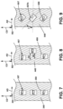
- FIG. 7 is a schematic of a portion of the outer liner 340 as seen from line VII-VII in FIG. 6 .
- An axial direction (denoted “AD”) extends parallel to the engine centerline 20 ( FIG. 1 )
- a radial direction (denoted “RD”) extends into the page and perpendicular to the axial direction AD
- a circumferential direction (denoted “CD”) is perpendicular to both the radial and axial directions RD, AD.
- the circumferential direction CD circumscribes the engine centerline and extends up and down the page when oriented in two dimensions as illustrated.
- the at least one opening 357 is multiple openings 357a, 357b, 357c.
- the multiple openings 357a, 357b, 357c are located at the same axial location and aligned along the circumferential direction CD.
- FIG. 8 is a schematic of variation of the portion of the outer liner 340 from FIG. 7 according to another aspect of the disclosure herein.
- At least one opening 457 is multiple openings 457a, 457b, 457c located within an outer liner 440 each defining a secondary combustor outlet 458.
- the multiple openings 457a, 457b, 457c are axially spaced from each other in the axial direction AD and unaligned in the circumferential direction CD.
- a first opening 457a is axially spaced from a second opening 457b a first amount (denoted "S1").
- a third opening 457c is axially spaced from the second opening 457b a second amount (denoted "S2").
- the second opening 457b can be located downstream from the first opening 457a and the third opening 457c.
- the third opening 457c can be located downstream from the first opening 457a and upstream from the second opening 457b.
- FIG. 9 is a schematic of variation of the portion of the outer liner 340 from FIG. 7 according to yet another aspect of the disclosure herein.
- At least one opening 557 is multiple openings 557a, 557b, 557c located within an outer liner 540 each defining a secondary combustor outlet 558.
- the multiple openings 557a, 557b, 557c are aligned along the circumferential direction CD and angled with respect to the axial direction AD.
- An axial orientation angle (denoted " ⁇ ") is an amount the at least one opening 557 is turned from the axial direction AD toward the circumferential direction CD.
- the orientation and location of the multiple discrete mini combustors 334 can embody any of the variations including a combination of the variations illustrated in FIG. 7, FIG. 8, and FIG. 9 .
- the orientation and location can be tuned to achieve sufficient mixing between the two exhaust gasses G1, G2.
- a method for controlling nitrogen oxides present within the combustion sections 14, 114, 214, 314 described herein includes generating the primary exhaust gasses G1 in the primary combustion chambers 46, 146, 246, 346 and generating secondary exhaust gasses G2 in the set of secondary combustors 50, 150, 250, 350 including the secondary combustion chambers 54, 154, 254, 354. The method further includes injecting the secondary exhaust gasses G2 into the main combustion zones 72, 172, 272 of the primary combustion chambers 46, 146, 246.
- the method can further include enhancing mixing of the primary and secondary exhaust gasses G1, G2 by injecting the secondary exhaust gasses G2 at the first, second, or third primary combustor angles ⁇ 1 , ⁇ 2 , ⁇ 3 described herein. Further, the method can include accelerating the flow of the primary fuel/air mixture FA1 and resulting primary exhaust gasses G1 by introducing the secondary fuel/air mixture FA2 via the multiple discrete mini combustors 334. Accelerating the flow of the primary fuel/air mixture FA1 and resulting primary exhaust gasses G1 can also be done by utilizing the annular mini combustor 34 arranged about the primary combustor 32. Further, the proximity of the set of secondary combustors 50 accelerates the primary exhaust gasses G1 as is illustrated in FIG. 3 .
- Benefits associated with the set of secondary combustors in combination with the primary combustor and methods described herein are to reduce NO x emissions even in a severe cycle with a higher operating air pressure, higher temperature, higher fuel/air ratio and with heated fuel.
- higher fuel/air ratio within a combustion system leads to a higher flame temperature which results in higher NO x .
- fuel can be split between these chambers thereby reducing the fuel/air ratio in each chamber and in turn achieving lower temperature and hence lower NO x emission.
- O 2 levels in the primary combustion chamber can be reduced, further reducing NO x emission.
- the combustions section herein can operate with 100% H 2 fuel.
- combustor as described herein can be for any engine having a combustor that emits NO x . It should be appreciated that application of aspects of the disclosure discussed herein are applicable to engines with propeller sections or fan and booster sections along with turbojets and turbo engines as well.
- a combustion section for a turbine engine comprising a primary combustor liner including an inner liner and an outer liner; a dome wall extending from the inner liner toward the outer liner; a dome inlet located in the dome wall and defining a first centerline; a primary combustor having a primary combustion chamber defined at least in part by the inner liner, the outer liner, and the dome wall, the primary combustion chamber having a primary combustor height; and at least one mini combustor having a secondary combustion chamber and a mini dome inlet, the secondary combustion chamber fluidly coupled to the primary combustion chamber and having a mini combustor height; wherein the mini combustor height is less than the primary combustor height.
- combustion section of any preceding clause further comprising a secondary combustor liner extending axially from the dome wall and terminating in a backwall, the backwall extending radially toward the mini dome inlet an amount equal to the mini combustor height.
- combustion section of any preceding clause further comprising at least one opening extending through the outer liner and located downstream from the dome inlet.
- the at least one mini combustor is multiple discrete mini combustors circumferentially arranged about the engine centerline and the at least one opening is multiple openings corresponding with the multiple discrete mini combustors.
- dome inlet defines a first centerline and the mini dome inlet defines a second centerline and the first centerline and the second centerline intersect to define a primary combustor angle in a radial plane.
- the dome inlet defines a first centerline and the mini dome inlet defines a second centerline and a primary combustor length is measured parallel to the first centerline between the dome wall and a primary combustor outlet and a main combustion length is measured parallel to the first centerline from the dome wall to the second centerline, wherein the main combustion length is from 5% to 90% of the primary combustor length.
- the dome inlet defines a first centerline and the mini dome inlet defines a second centerline and a primary combustor length is measured parallel to the first centerline between the dome wall and a primary combustor outlet and a main combustion length is measured parallel to the first centerline from the dome wall to the second centerline, wherein the main combustion length is from 5% to 90% of the primary combustor length.
- a turbine engine comprising a compressor section, a combustion section, and a turbine section in serial flow arrangement along an engine centerline, the combustion section comprising a primary combustor liner including an inner liner and an outer liner; a dome wall extending from the inner liner toward the outer liner; a dome inlet located in the dome wall and defining a first centerline; a primary combustor having a primary combustion chamber defined at least in part by the inner liner, the outer liner, and the dome wall, the primary combustion chamber having a primary combustor height; and at least one mini combustor having a secondary combustion chamber and a mini dome inlet, the secondary combustion chamber fluidly coupled to the primary combustion chamber and having a mini combustor height; wherein the mini combustor height ranges from 0% to 60% of the primary combustor height.
- a method for controlling nitrogen oxides present within a combustion section comprising generating primary exhaust gasses in primary combustion chambers and generating secondary exhaust gasses in a set of secondary combustors including a set of secondary combustion chambers.
- any preceding clause further comprising enhancing mixing of the primary and secondary exhaust gasses by injecting the secondary exhaust gasses at a first, second, or third primary angle.
- any preceding clause further comprising accelerating a flow of a primary fuel/air mixture and resulting primary exhaust gasses by locating the set of secondary combustors 50 in close proximity to the primary combustion chamber.
Landscapes
- Engineering & Computer Science (AREA)
- Chemical & Material Sciences (AREA)
- Combustion & Propulsion (AREA)
- Mechanical Engineering (AREA)
- General Engineering & Computer Science (AREA)
- Fluidized-Bed Combustion And Resonant Combustion (AREA)
Applications Claiming Priority (1)
| Application Number | Priority Date | Filing Date | Title |
|---|---|---|---|
| US202318473615A | 2023-09-25 | 2023-09-25 |
Publications (2)
| Publication Number | Publication Date |
|---|---|
| EP4528164A2 true EP4528164A2 (de) | 2025-03-26 |
| EP4528164A3 EP4528164A3 (de) | 2025-04-09 |
Family
ID=92212789
Family Applications (1)
| Application Number | Title | Priority Date | Filing Date |
|---|---|---|---|
| EP24192505.6A Pending EP4528164A3 (de) | 2023-09-25 | 2024-08-02 | Verbrennungsabschnitt mit einer primärbrennkammer und einem satz von sekundärbrennkammern |
Country Status (2)
| Country | Link |
|---|---|
| EP (1) | EP4528164A3 (de) |
| CN (1) | CN119687479A (de) |
Family Cites Families (5)
| Publication number | Priority date | Publication date | Assignee | Title |
|---|---|---|---|---|
| JPS5847928A (ja) * | 1981-09-18 | 1983-03-19 | Hitachi Ltd | ガスタ−ビン燃焼器 |
| US5156002A (en) * | 1990-03-05 | 1992-10-20 | Rolf J. Mowill | Low emissions gas turbine combustor |
| FR2672667B1 (fr) * | 1991-02-13 | 1994-12-09 | Snecma | Chambre de combustion pour turboreacteur a faible niveau d'emissions polluantes. |
| DE4318405C2 (de) * | 1993-06-03 | 1995-11-02 | Mtu Muenchen Gmbh | Brennkammeranordnung für eine Gasturbine |
| US20190017441A1 (en) * | 2017-07-17 | 2019-01-17 | General Electric Company | Gas turbine engine combustor |
-
2024
- 2024-08-02 EP EP24192505.6A patent/EP4528164A3/de active Pending
- 2024-09-23 CN CN202411326351.1A patent/CN119687479A/zh active Pending
Also Published As
| Publication number | Publication date |
|---|---|
| EP4528164A3 (de) | 2025-04-09 |
| CN119687479A (zh) | 2025-03-25 |
Similar Documents
| Publication | Publication Date | Title |
|---|---|---|
| US11747018B2 (en) | Combustor with dilution openings | |
| US12590561B2 (en) | Combustor with lean openings | |
| US11578871B1 (en) | Gas turbine engine combustor with primary and secondary fuel injectors | |
| US12560324B2 (en) | Combustion section with a primary combustor and a set of secondary combustors | |
| US20260009352A1 (en) | Gas turbine engine and fuel nozzle assembly therefor | |
| US11828465B2 (en) | Combustor fuel assembly | |
| US11885498B2 (en) | Turbine engine with fuel system including a catalytic reformer | |
| US12173898B1 (en) | Combustion section with a primary combustor and a set of secondary combustors | |
| EP4530533A1 (de) | Brennkammer mit einer primärbrennkammer und einer sekundärbrennkammer | |
| CN116498995B (zh) | 涡轮发动机以及用于涡轮发动机的燃烧器 | |
| EP4528164A2 (de) | Verbrennungsabschnitt mit einer primärbrennkammer und einem satz von sekundärbrennkammern | |
| US20230194088A1 (en) | Combustor with dilution openings | |
| US12429220B2 (en) | Combustion section with a primary combustor and a set of secondary combustors | |
| EP4530532A1 (de) | Verbrennungsabschnitt mit einer primärbrennkammer und einem satz von sekundärbrennkammern | |
| EP4722592A1 (de) | Turbinenmotor mit einer brennstoffdüse | |
| EP4722594A1 (de) | Gasturbinenmotor mit brennstoffdüsenanordnung | |
| US12590556B1 (en) | Gas turbine engine, fuel nozzle assembly, and method | |
| EP4722593A1 (de) | Gasturbinentriebwerk und brennstoffdüsenanordnung dafür | |
| EP4202301A1 (de) | Brennkammer mit verdünnungsöffnungen | |
| US20260092705A1 (en) | Gas turbine engine and fuel injector assembly therefor |
Legal Events
| Date | Code | Title | Description |
|---|---|---|---|
| PUAI | Public reference made under article 153(3) epc to a published international application that has entered the european phase |
Free format text: ORIGINAL CODE: 0009012 |
|
| STAA | Information on the status of an ep patent application or granted ep patent |
Free format text: STATUS: THE APPLICATION HAS BEEN PUBLISHED |
|
| PUAL | Search report despatched |
Free format text: ORIGINAL CODE: 0009013 |
|
| AK | Designated contracting states |
Kind code of ref document: A2 Designated state(s): AL AT BE BG CH CY CZ DE DK EE ES FI FR GB GR HR HU IE IS IT LI LT LU LV MC ME MK MT NL NO PL PT RO RS SE SI SK SM TR |
|
| AK | Designated contracting states |
Kind code of ref document: A3 Designated state(s): AL AT BE BG CH CY CZ DE DK EE ES FI FR GB GR HR HU IE IS IT LI LT LU LV MC ME MK MT NL NO PL PT RO RS SE SI SK SM TR |
|
| RIC1 | Information provided on ipc code assigned before grant |
Ipc: F23R 3/50 20060101ALI20250228BHEP Ipc: F23R 3/42 20060101ALI20250228BHEP Ipc: F23R 3/34 20060101ALI20250228BHEP Ipc: F23R 3/06 20060101AFI20250228BHEP |
|
| STAA | Information on the status of an ep patent application or granted ep patent |
Free format text: STATUS: REQUEST FOR EXAMINATION WAS MADE |
|
| 17P | Request for examination filed |
Effective date: 20250916 |